

Page 1
Page 2

Page 3

Table of Contents
Chapter 1: Introduct ion 5
Overview 5
Main Features of the LE/LE-HC Series 5
Chapter 2: Getting Started 7
General Description 7
First time starting the LE/LE-HC Series DVR 7
Configuration and operation via the Infrared Remote (IR) Control 7
LE/LE-HC Series Networking 7
Chapter 3: LE/LE-HC/HC Series Network Operations 8
Default Configuration 8
Network Installation 8
Testing the Network Connection 8
Chapter 4: Configuring the LE/LE-HC Series DVR 10
First Connection to LE/LE-HC Series DVR 10
Configuration of LE/LE-HC Series DVR 10
Advance Setting 11
a) System Information 11
b) Camera Settings 11
c) Audio Setting 12
d) Set Date & Time 13
e) Set NTP Server 13
f) System Configuration 13
g) Serial Ports 15
h) Set User’s Authority 16
i) DVR Setup 16
j) Record Schedule 16
k) Motion Detection 17
l) Set Pre-Alarm 17
m) Playback and search 18
n) Send Mail 19
o) FTP Upload 20
p) View Video without Plugins 20
Chapter 5: Configuring DVR using Remote Control 21
Configure LE/LE-HC Series for a network with Remote Control 21
Using the Menus 21
a) Use the Menus 21
b) Operating the Menus and
c) View the Previous/Next Page 22
d) Exit the Menus 22
e) Video Recording Setup 22
System Setup (Configuration) in IR Mode 23
a) Password Protect 23
b) Video 23
Changing the setting Parameters 22
- 2 -
Page 4

c) Video Input 25
d) Disks 26
e) TV Output 26
f) OSD Text 26
g) TCP/IP Settings 26
h) Account Settings 27
i) Audio 27
j) Serial Ports 27
k) System Information 28
l) Date/Time 30
m) Alarm 29
n) ISP 29
o) Registry Server Setting 29
p) Running Mode 29
q) Algorithm Setting 30
r) NTP Setup 30
Configure recording in IR Mode 31
Motion Detection 32
Playback with IR Controller 33
System Shutdown 35
Chapter 6: Configuring LE/LE-HC Series DVR using GUI mode 36
Playback (Viewing recorded events) 40
System Setup (Configuration) 45
a) System Setup 45
b) Record Setup 56
c) Motion Detection 59
Chapter 7: Using PTZ Cameras in IR Mode 61
Appendix A 62
Appendix B 64
- 3 -
Page 5

Page 6

LE/LE-HC Series DVR User Manual
V1.4 October 2006
Chapter 1: Introduction
Overview
Thank you for purchasing the LE/LE-HC Series Dig ital Video Recorder. This product is ideal for all
of today’s video security needs. From home users to industrial applications, the LE/LE-HC Series
DVRs can do it all – simply, completely and reliably. This high performa nce D VR has a built-in
dedicated web server, and record and display ca pability. Video is compressed using one of
several user selectable compression algorithms called codecs (compressor/decompressor). The
system will record this data onto a hard drive, overwriting the oldest recordings first, when the disk
is full. Video is displayed on a SVGA Monitor. The base system has four cameras, which can be
upgraded to a total of sixteen cameras (depending on the model purchased ) with no loss of frame
rate.
This DVR is unique in that the software is contained (embedded) in a firmware mod ule called a
DOM, which allows a fresh “re-install” every time the system is turned on. No need to w orry about
the traditional problems of viruses, Trojans, software glitches o r other Windows™ based issues as
the install is completely fresh every time. A small area of the module contains the user configured
data. No software is contained on the hard drive, so software cannot be corrupted.
Adding additional cameras to the system is as sim ple as turning off the DVR, plugging in another
four camera connector card, and turning it back on. Configuration is done in GUI mode with a
mouse, by the included remote controller in fu ll screen mode or through a remote PC. This remote
PC control allows users to switch cameras, control any PTZ cameras installed, and change all the
features of the DVR, with the appropriate password authority.
The DVR is accessible through the Internet, or a local Intranet, with some simple configuration
modifications to the DVR. Through a regist ry server the LE/LE-HC Series DVR supports Dynamic
IP addresses.
The remote software is all browser based and accessible using any reasonably current version of
Windows™ Explorer. Linux, Mac and some PDAs are supported through additional (included)
software.
Main Features of the LE/LE-HC Series
Ease of use
Plug and play, non-Windows™ embedded real-time OS
Simple configuration via keyboard/mouse, IR Controller or Internet/LAN
Uses a standard web browser for remote PC access.
Video & audio recording
Up to 16 camera inputs (color or B/W) are supported in multiples of four.
Adding cameras is accomplished by installation of additional cards.
Up to 30 fps is provided on each camera for local monitoring
Record / display / playback/ remote access simultaneously
Built-in Multiplexing with local monitoring
Local playback of recorded video on VGA monitor
Remote playback of recorded video using standard PC browser
- 5 -
Page 7

LE/LE-HC Series DVR User Manual
V1.4 October 2006
Search recorded data by date, time & events
Control multiple brands of PTZ Cameras
High video quality and low data rate
Up to 200:1 video compression
Multiple video compression engines:
LE: MPEG4, H.263, JPEG, M-JPEG
LE-HC: MPEG4
Networking is supported and allows remote access
Dynamic IP support for Internet access
Direct Dial-up available with optional external modem
Backup
CD or DVD writer
Alarm function
Motion detection / Event trigger / Schedule / Pre-alarm recording
E-Mail, FTP and Voice Call alarm notification
Optional GPI/O for alarm control
Customization
Supports HTML file upload for home page customization
- 6 -
Page 8

LE/LE-HC Series DVR User Manual
V1.4 October 2006
Chapter 2: Getting Started
General Description
Configuring the LE/LE-HC Series DVR can be accomplished in several ways. The Infrared
Remote Control included with the LE/LE-HC Series DVR works in IR Mode when the receiver is
connected to a USB port on the back of the LE/LE-HC Series DVR. Alternatively, in GUI Mode
(Graphic User Interface) a mouse and keyboard can be used. If configured for LAN or Internet, a
web browser can be used to configure the DVR.
We have found the easiest way to configure the system is to use the Infrared Remote Control to
configure the IP settings, then once on the net use the remote configuration from an alternate PC.
First time starting the LE/LE-HC Series DVR
Before turning the DVR on, connect the appropriate video inputs, monitor and network adapter to
the back of the DVR. The system will automatically detect the video mode (NTSC or PAL) of the
cameras connected (default is NTSC if no cameras are connected). Symptoms of incorrect video
configuration are B/W video when color is expected or the top or bottom of the video cut off.
The LE/LE-HC Series records automatically on power up. The Default IP address is
192.168.10.10, which is within the range of most Intranets. The Sub-net mask is preset to
255.255.255.0, also within the range of most intranets.
Configuration and operation via the Infrared Remote (IR) Control
Chapter 5: Details the operation of the IR Control.
LE/LE-HC Series Networking
Chapter 3: Details the operation of the Networking Operations.
- 7 -
Page 9
LE/LE-HC Series DVR User Manual
V1.4 October 2006
Chapter 3: LE/LE-HC Series Network Operations
Default Configuration
The LE/LE-HC Series DVR comes preconfigured. A list of the default settings is included in
Appendix A of this document.
Network Installation
The LE/LE-HC Series DVR comes preconfigured as a static IP. TCP/IP networks either have the
IPs assigned manually, or by a DHCP (Dynamic Host Configuration Protocol) Server. Most
Internet routers and Windows 2000 Server™ use DHCP to assign IP addresses. The reason for
assigning a static IP within this environment is that when a leased IP from a DHCP server runs out
(which can happen every day), the LE/LE-HC Series DVR may not re-acquire the old IP address.
This will break functionality within the Intranet or LAN environment and will break any port
forwarding assigned within the router that allows external (internet) users to connect to the LE/LEHC Series DVR.
Most networks using a router or a Windows 2000 Server © should be able to see the LE/LE-HC
Series DVR once it is connected.
In the case the IP address pre-assigned to the LE/LE-HC Series DVR (192.168.10.10) may
already be assigned to another networking device; finding another machine on the network and
attempting to ping that IP address will tell if there is a unit already connecting on that specifi c IP (if
it says no IP found, it’s a good indication that there is no unit connected at that IP). Use the ping
method in figure 3.1 but instead of times<1ms or similar (up to 200ms), look for Request Timed
Out. This indicates that there is no computer currently on the network at that locat ion. Failure to
check this could cause the LE/LE-HC Series DVR to push another machine off the network or
cause other problems.
In cases where this machine is connected directly to a DSL modem or Cable Modem, these steps
may be ignored; however, additional configuration is usually required.
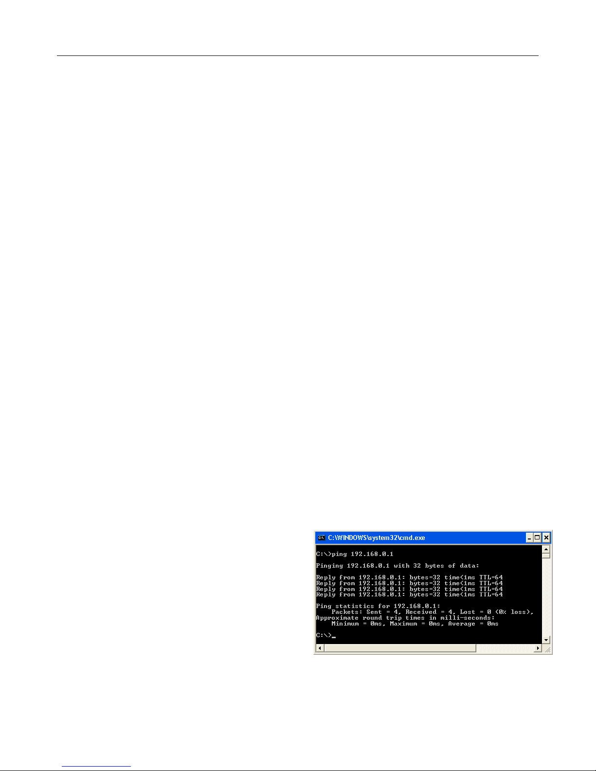
Testing the Network Connection
From any computer on the network, click on the
start button and click on run (Windows 98, ME,
2000, XP). Type in command and click OK. This
will bring up a DOS prompt. Type in PING
192.168.10.10. A good connection will look like
Figure 3.1
If the ping fails, check all the wires to make sure
there are connected. Look at the back of the DVR
and on the device to which the other end of the
cable is connected (a switch, router or hub most
likely). Make sure that the connection lights are
on, on both ends. Unplugging and reconnecting cables can fix many problems. Rebooting the
Figure 3.1
- 8 -
Page 10
LE/LE-HC Series DVR User Manual
V1.4 October 2006
DVR is required if the light is off, and pushing the connector turns the light on. These lights will
usually be located right next to the connector plug on the DVR, and there are usually a bank of
lights on the router that show valid connections. If in doubt, unplug the cable and see if one of the
lights goes out.
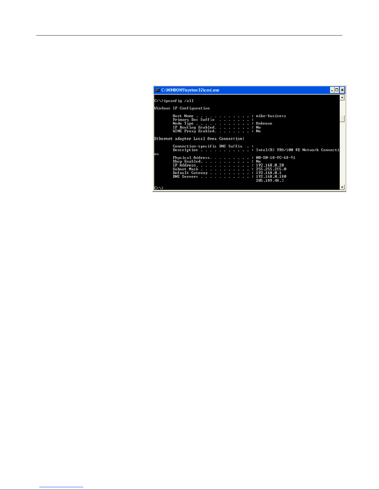
Once a physical connection has
been established, the next thing
to check is the network setting s.
The first step is to bring up a
DOS prompt. From any
computer on the network, click on
the start button and click on run.
(Windows™ 2000, XP). Type in
“command” and click OK. This
will bring up a DOS prompt.
Type in “ipconfig /all”, and press
enter. If all goes well, Figure 3.2.
The information needed is the
subnet mask, default gateway,
and DNS Servers. Note the IP
Figure 3.2
addresses. The number after the last “dot”, e.g. in 192.168.0.20, the number 20 is the one to
change for the DVR. Picking a number above 200 (max is 254) should be OK, unless the unit is
being installed in a large networking envi ronment. In that case, they will have a network
administrator who knows the exact settings required.
The LE/LE-HC Series can be assigned a dynamic IP by a DHCP Server (usually a router or
Windows 2000 Server) by assigning the DVR IP address 255.255.255.253. This does give the
added complication of finding out what IP was assigned, and while there is software that can
locate the LE/LE-HC Series DVR on the network, it is easier to assign a static IP.
- 9 -
Page 11

LE/LE-HC Series DVR User Manual
V1.4 October 2006
Chapter 4: Using and Configuring the LE/LE-HC Series DVR
Remotely
First Connection to LE/LE-HC Series DVR
Once the LE/LE-HC Series DVR is installed on the network, use
another Windows© based machine on the network and try to
connect to the LE/LE-HC Series DVR -accomplished by opening
up a browser and entering in the address bar http://192.168.10.10
(or the configured IP address for the LE/LE-HC Series DVR)
A window should pop up looking like figure 4.1. Note that the IP
may differ depending on what was configured. The default
Administrator name is “ad min” and the password is
“sentry”. This will al lo w remote access to the LE/LE-HC
Series DVR.
To view live video from a LE/LE-HC Series DVR
remotely, a Live Video Activ e X Component is required.
If the Active X Component has never been installed, or a
previous version is on the remote machine, a w indow will
pop up which requests downloading LVSETUP.EXE (see
figure 4.2).
Figure 4.1
Figure 4.2
Configuration of LE/LE-HC Series DVR
When connecting to The LE/LE-HC Series DVR from a remote PC, the web browser display will
be Figure 4.3.
Playback recorded files
System Setup
The Surveillance Screen Pa nel
enables the definition of the number
of camera images di splayed on
screen.
Figure 4.3
- 10 -
Page 12
LE/LE-HC Series DVR User Manual
V1.4 October 2006
Similar local configuration options are available with the GUI and IR interface, although the easiest
method for configuration is the remote configuration.
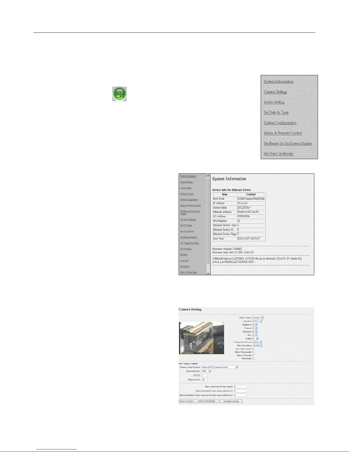
Advance Setting
After the initial login, typing in the URL in Section 3.4 will bring up the page in
Figure 4.4. Clicking on the
(System Setup) button will display the
screen which is partially shown in Figure 4.5 (C licking on System Setup will
bring up a login prompt if the original Password and User ID do not have
sufficient privilege).
Making changes to the settings will often cause the LE/LE-HC Series DVR to
reboot when the done button is clicked. This is unavoidable, and video will
not be recorded while the DVR is rebooting. This process can take 3 to 4
minutes.
Each of the items in the list in Figure 4.4 are
covered in the following subsections of Section
4.3
a) System Information
This page gives information about the LE/LE-HC
Series DVR. Most of this information isn’t
required on a day to day basis, but ma y be
required by a network administrator or
Technician should the occasion arise .
b) Camera Settings
1. Video Source: Select camera to display
2. Brightness, Contrast, Sa tu ration, Hue and
Quality: Change Brigh tness, Contrast,
Saturation, Hue and Quality here. These
parameters are applied to all cameras. To adj u s t
brightness of each individual camera, please use
“Gain Control” as described in Item 5.
3. Compression Boost: Selection can be “None”,
“Low”, “Medium” and “High” to adjust video
compression rate. The higher the “Compression
Boost” level, the smaller the compressed frames
become providing faster remote trans missions
and smaller recorded files but poorer video
quality.
Figure 4.5
Figure 4.4
- 11 -
Page 13
LE/LE-HC Series DVR User Manual
V1.4 October 2006
Figure 4.6
4. Video Resolution: Selection can be either 320x240 or 640x480. A higher resolution will provide
better video quality but will use more hard drive space and bandwidth.
5. Auto Gain Control: When this box is checked, the LE/LE-HC Series will keep the GAIN value
effective automatically no matter day or night, light or dark.
6. Mirror Horizontally: Self Explanatory
7. Mirror Vertically: Self Explanatory
8. Watermark: Inserts watermark into picture.
Set Camera Control (PTZ camera configuration settings)
1. Camera Control Device: Use the drop-down menu to select the correct PTZ protocol.
2. Baud Rate(bps): Select the correct PTZ camera baud rate.
3. PTZ ID: Enter the PTZ ID (set directly on the camera)
4. Timeout (sec): Select desired timeout; default is 120 seconds
Other Settings
1. Max connections for this camera: Limit the maximum number of concurrent (remote)
connections to this camera.
2. Max bandwidth for this camera (Bytes/sec): Limit the maximum bandwidth in Bytes/second
allocated to this camera.
3. Max bandwidth of each connection for this camera (Bytes/sec): Limit the maximum bandwidth
allocated to each connection of this camera.
Click the “Done” button to save any settings changes.
Note: Please click “Write To FlashROM!” to save data
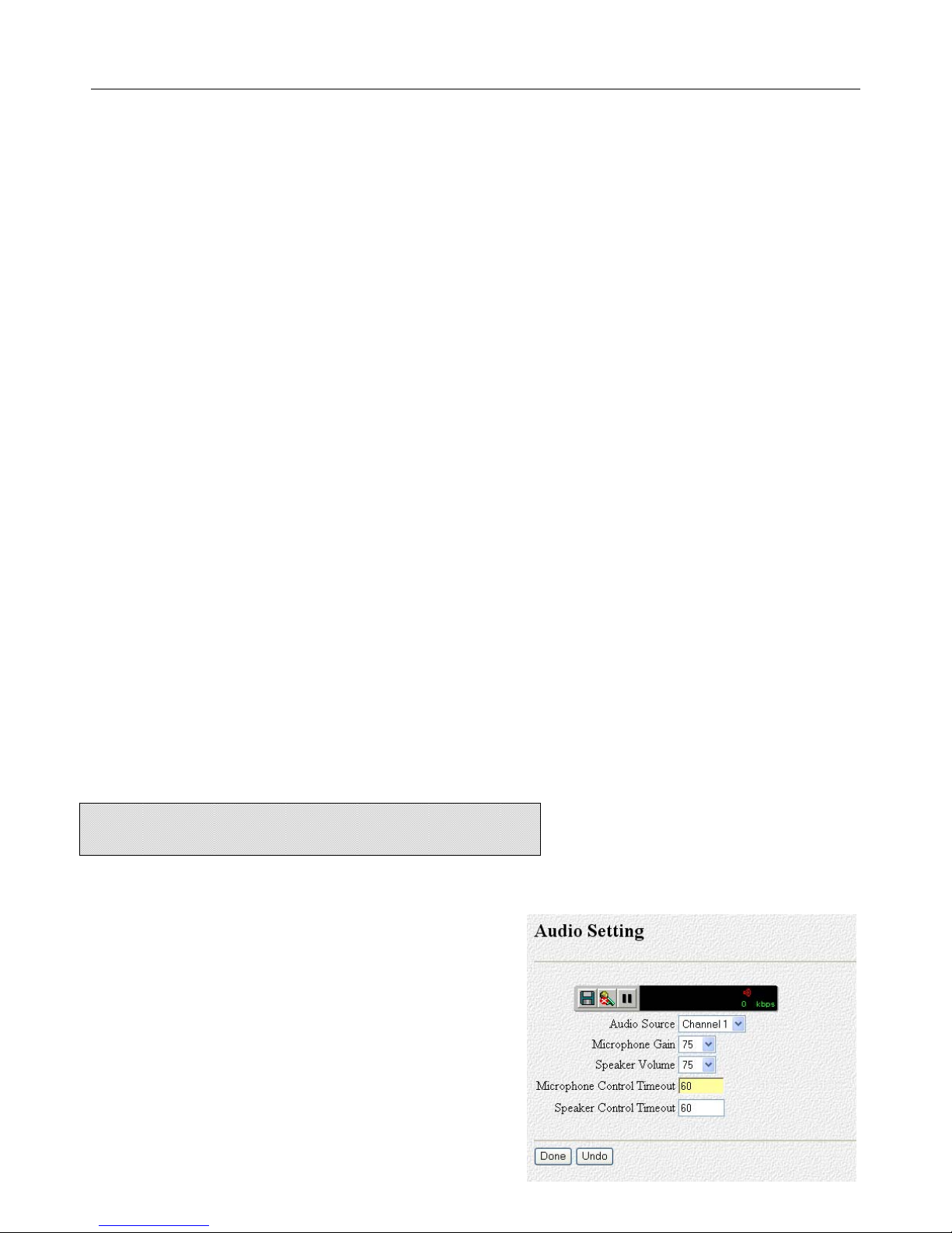
c) Audio Setting
Users accessing this for the first time will be required
to download LASETUP.EXE if they have not listened
to audio previously.
1. Audio Source. Select the source to modify.
- 12 -
Figure 4.7
Page 14

LE/LE-HC Series DVR User Manual
V1.4 October 2006
2. Microphone Gain: Similar to video gain, it amplifies the signal before audio is processed
3. Audio Selection; Choose which camera to associate audio with. * LE-HC has one channel of
audio per video.
3. Speaker Volume: Controls the volume of the speaker
4. Microphone Control Timeout and Spe aker Control Timeout determine the length of time that
one remote user can have control of the microphone and speaker.
Currently the LE Series supports a single channel of audio recording.
d) Set Date & Time
Follow the formats when setting the time and date.
e) Set NTP Server
NTP stands for Network Time Protocol. It is a protocol to request
the current time from a time server. Connection to the internet is
required. Check the enable box to turn the Network Time
Figure 4.8
Protocol service on or off. Set the period to however many
hours, and once per that period, the time will be updated.
Once every 24 hours should be sufficient, if required at all.
Keep in mind that this is a service offered by educational and
government institutions and abuse will result in our loosing
these public time servers. This feature is not generally
required, but a neat feature none the less.
f) System Configuration
This section is broken down into several parts, as this page is
longer than one screen capture will permit. Each of the
configuration options are outlined below:
ISP mode is used when the DVR is connected directly to
a telephone modem. This mode is generally too slow to
see any sort of reasonable data throughput and should
be avoided if at all possible. Configuring ISP mode is
completed in the “ISP Setting” dialog box at the bottom
of Figure 4.10. Phone number, user ID, and password
as well at maximum baud rate should all be entered. If
the ISP assigns an IP address, then configure that in the
TCP/IP settings and check the “Use assigned TCP/IP
Settings” check box.
Network Mode is the default setting and in most
circumstances, the LE/LE-HC Series DVR will be
connected to a network of some sorts. It could be
Figure 4.9
Figure 4.10
- 13 -
Page 15
LE/LE-HC Series DVR User Manual
V1.4 October 2006
connected to a cable connection or DSL line. DSL that uses PPPoE would require a router as
PPPoE requires a login procedure, which is not supported by the LE/LE-HC Series DVR.
Network Mode settings a r e set in “TCP/IP Settings”
. These need to be configured to have the
LE/LE-HC Series DVR communicate over a network or the Internet.
This area really should not need to be changed, once set, as the connection to the network is
functional.
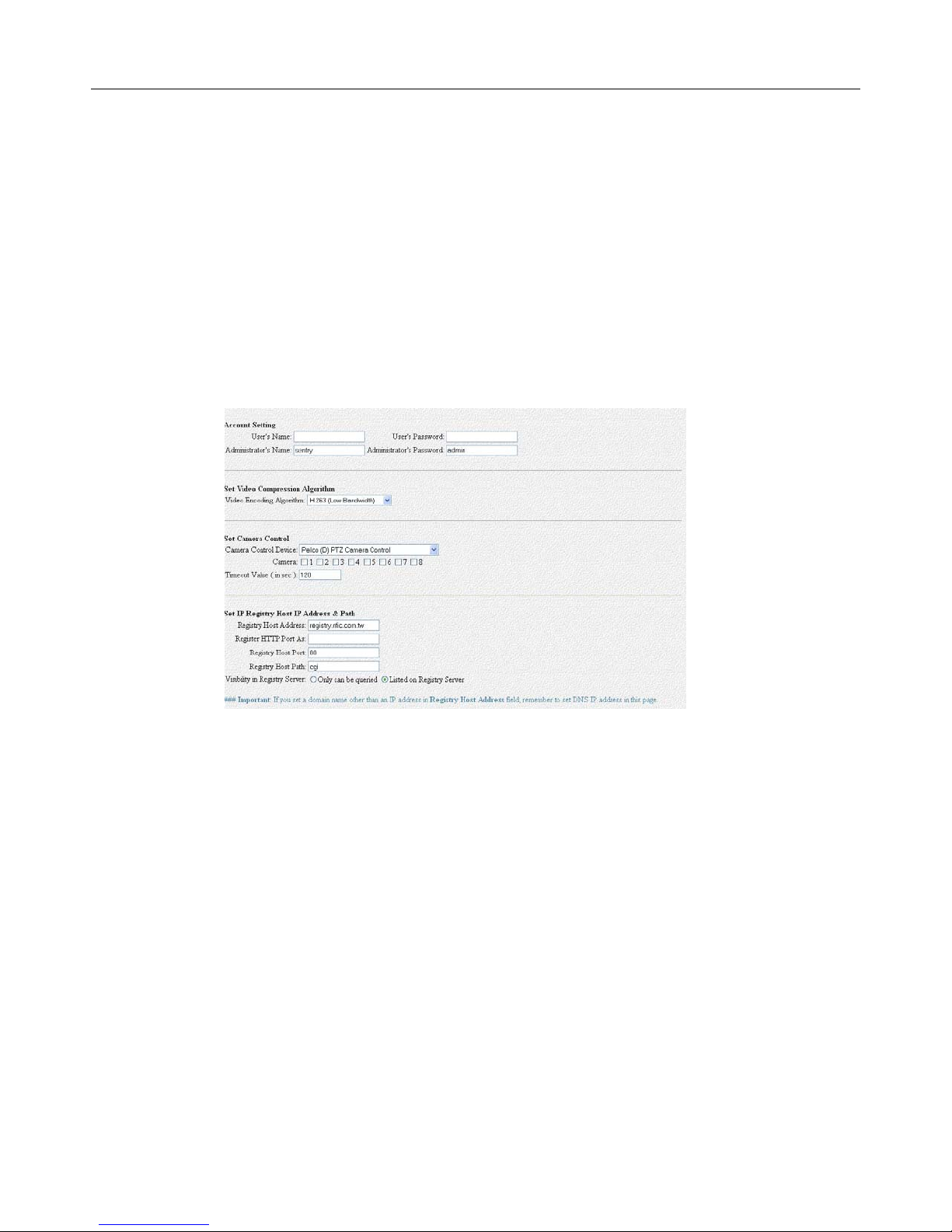
Account Setting
Under account setting there are two levels of users. Privileges for the user are configured in the
“Set User’s Authority” section covered later in this chapter.
Figure 4.11
- 14 -
Page 16
LE/LE-HC Series DVR User Manual
V1.4 October 2006
Set Video Compression Algorithm & Resolution
Select one of four Compression algorithms. These ar e MPEG4, H.263, JPEG or Motion-JPEG.
Please refer to the table below for relationship between Compression format, Video quality & Data
rate:
Compression Format Video Quality Data Rate
JPEG Very Good High
M-JPEG Good High (Less than JPEG)
H.263 Average Low
MPEG4 Good Low
*Please Note: The only compression format available on the LE-HC is MPEG4.
The best compression format depends on network connections; both locally and rem ote.
Remember that a 3 MB DSL connecti on me ans 3 MB download, not 3 MB upload. The 3 MB DSL
can be as low as 284K upload or even 128K. This will have an affect on the remote video frame
rate. Observing video produced remotely under different compression algorithms is the best way
to evaluate requirements. The LE Series DVR is set to H.263 compression as a default. This
provides the fastest video transmission speeds, t he smallest recorded files and satisfactory video
quality.
When setting video resolution, remember that 640X480 resolution needs 4 times the physical
bandwidth than that required to produce the same frame at 320X240. Once again, look at the
video and see if the speed loss of frames is worth the increase in resolution quality.
“Set IP Registry Host IP Address & Path” is used where static IPs are unavailable or
impractical. Basically, the LE/LE-HC Series DVR sends its current IP to a computer designated as
a registry (usually a commercial service). Remote users can then access that registry and find out
what the current IP is. This is an impreci se service at best, and is prone to failure, due to the
nature of the internet. However, in cases where a static IP is not available, it is still invaluable.
g) Set Serial Ports
Settings for COM1 and COM2 need only be applied in cases where a GPIO, Modem or PTZ,Voice
Call, Data Capture, Control device is connected to the D VR.
Settings for these particular devices will vary by brand. Specific questions regarding this topic
should be directed to the vendor. Please be aware that not all brands (especially PTZ cameras)
are compatible with this DVR.
- 15 -
Page 17
LE/LE-HC Series DVR User Manual
V1.4 October 2006
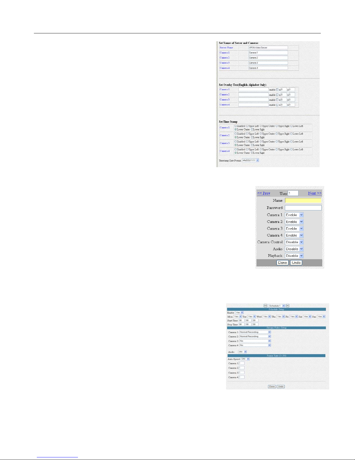
Set Names & On Screen Display (Figure 4.12)
The “Set Names of Server and Cameras” option allows
users to change the name of the server and the camera
names.
Use the “Set Overlay Text” to show text on the camera
image. Check the enable box to make it appear on the
screen and set the X and Y parameters (X being horizontal
and Y being vertical) to assign a specific position (default is
upper left hand corner).
Additionally a time stamp can be configured, per camera
with the “Set Time Stamp” and give a format for the date by
selection from the pull-down menu labeled “Timestamp Date
Format.”
h) Set User’s Authority (Figure 4.13)
Setting the User’s Authority allows the administrator to configure users to have specific privileges
defined by lo gi n c r e d e nt ials.
Simply enter a user name and password for the user and then configure
the desired privileges for that user.
Below the box is a URL marked Users Listing which gives a list of all the
users on the DVR.
Figure 4.12
i) DVR Setup
DVR Setup Defines whether the LE/LE-HC Series DVR will record based
on a first-in first-out recording process, oldest video getting deleted to
Figure 4.13
make room for new video (circular recording) or if it will stop when the drive is full (Auto Stop).
j) Record Schedule
Multiple schedules can be set up to accomplish specific
recording requirements at pre-determined times. This would
allow maximum usage of hard drive capacity, for instance
recording on motion when a store is closed and recording full
time when the store is open. Use the pull-down menu at the top
of the screen in Figure 4.14 to select the schedule to edit.
There can be a maximum of 16 schedules on any one DVR at
any one time.
Schedule 1 is set by default to be on all the time. Unlike most
traditional DVRs the LE/LE-HC Series DVR uses a schedule all
the time. Care must be taken not to overlap schedules. Use
Figure 4.14
- 16 -
Page 18
LE/LE-HC Series DVR User Manual
V1.4 October 2006
the schedule setup section to configure start time and stop time (make both 00:0 0:00 for the full
day) and then pick the days of the week this is to be effective. Make sure to turn the “Enable” pull
down menu to “Yes” or the schedule will not run.
Use “Stream Video Setup” to indicate if the camera should record using motion detection, full time
or not have it turned on at all.
For the frame rate, in most instances, auto speed should be turned on. This will give the best
frame rate. However, each camera can be set to record between 1 and 30 frames per second but
total frames added up together cannot be higher than the LE/LE-HC Series DVR is capable of
recording.
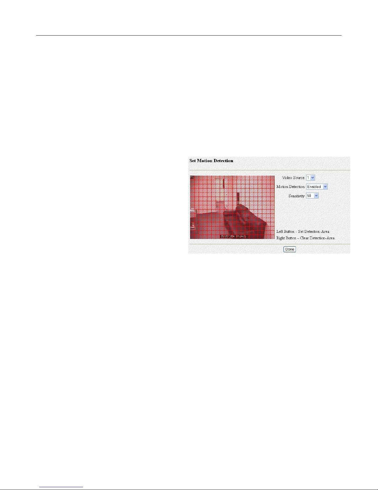
k) Set Motion Detection
When motion detection recording is selected in
Section 4.3.0 the specifics of motion detection
are configured in this section. Select the video
source (camera). The camera imag e will show
on the left hand side of the screen as in Figure
4.15. Use the left mouse button to click on
squares to set detection area and use the right
mouse button to clear areas. Hold down the
left or right mouse button and drag to block
areas larger than single squares. Motion will
only be detected in areas that have the Set
Detection squares, marked in red.
Figure 4.15
l) Set Pre-Alarm
Use the “Set Pre-Alarm” to set the number of frames recorded before an alarm condition exists.
Each camera can be configured separately and be configured differently.
- 17 -
Page 19
LE/LE-HC Series DVR User Manual
V1.4 October 2006
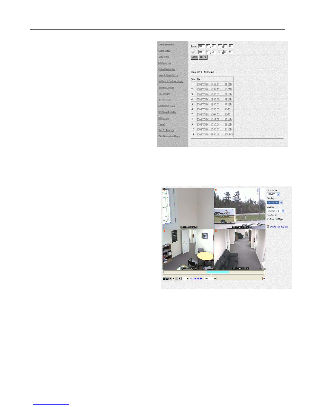
m) Playback and Search
To bring up a list of recorded video on the
LE/LE-HC Series DVR, either click List All or
set a time frame in the from/to folders and then
click query. The files will be listed in the lower
screen area (see Figure 4.16) and clicking on
one will open the play video screen.
If this is the first time attempting to play back
recorded video on a remote machine (and for
each separate unit accessing remotely) users
will be required to download the
RPSETUP.EXE file when they attempt to play
the video. Download and install the file. Close
the window that says “player not found” and
attempt to play the video file again.
Once the ActiveX component is successfully installed, the video display screen should appear as
in Figure 4.17.
Use the “Dimension” pull down button to
configure the size of the video on the display.
The “Display” button will s elect the number of
cameras displayed on the screen at any one
time, and the “Camera” button will select which
particular subset (less than 16 cameras
selected) is shown. In most cases, for DSL and
cable connections, select high bandwidth. In
times when the bandwidth available is not very
good, select low bandwidth.
Use the “Download and Save” hyperlink, to save
the video on the remote PC.
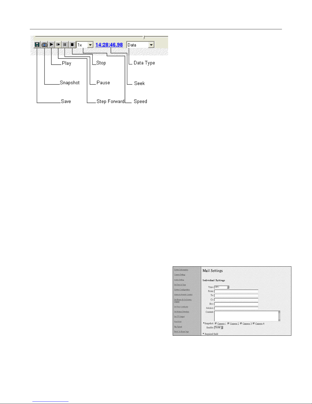
At the bottom left hand corner there are six buttons and some other options. These are explained
in Figure 4.18 below:
Figure 4.16
Figure 4.17
- 18 -
Page 20
LE/LE-HC Series DVR User Manual
V1.4 October 2006
Figure 4.18
Save: Save the data file on the local machine.
Snapshot: Clicking this button brings up a list of Cameras. Select the camera from the
list to snapshot, and then click o.k. It will then bring up a Webpage with the
picture in it, which may be saved by right clicking on the image and selecting
“Save Image As”.
Play: Play video.
Step Forward: When the pause button is pressed, “Step Forward” will move each camera
forward one frame.
Stop: Stop video playing.
Data Type: When data is selected, all recorded video will be played. Selecting motion will
only play video that was recorded based on motion. GPI will play video that
was recorded by an alarm trigger
Seek: Allows specific times to be entered and the video will zoom to that time.
Speed: Playback speed
Use the slider bar above this image to move around
within the time selected. Please note that using the
slider bar or the seek option will cause a delay of
several seconds while the video switches.
n) Send Mail
The mail settings configuration page (Figure 4.19) is
used to alert configured email recipients when specific
events occur on the LE/LE-HC Series DVR.
As many Motion Detect Types (Events) as cameras can trigger an email and an be set for each
camera over a specific time range. Each event must be enabled to send emails. Enable them by
using the pull down menu “Enable” and select enable. Enter appropriate data into the From, To,
Figure 4.19
- 19 -
Page 21

LE/LE-HC Series DVR User Manual
V1.4 October 2006
CC, BCC subject and comment fields. Select the camera image(s) to be sent by email using the
checkboxes alongside Snapshot.
Global settings need to be configured to communicate with the
mail server used by the network or Internet. This information is
needed by the LE/LE-HC Series DVR to effectively email over the
internet, or within a LAN. An existing account can be used or a
new account can be created. Please get this information from the
network administrator or Internet Service Provider. It is very
important to note that if the mail server is not an IP address, then
a DNS (domain name server) must be identified in syste m
Figure 4.20
configuration.
o) FTP Upload
FTP Upload allows the DVR to send pictures to an FTP Site. The functionality is identical to the
mail settings, just configured for an FTP server instead of a mail serve r.
p) Configuration File
This feature allows the user to backup all the settings of the DVR and restore the settings should
the need arise.
- 20 -
Page 22

LE/LE-HC Series DVR User Manual
V1.4 October 2006
Chapter 5: Using and Configuring the LE/LE-HC DVR with Remote
Control
All available settings of the LE/LE-HC Series DVR can be configured using the remote controller
included with the system or with mouse and keyboard in GUI mo de or remotely from a connected
PC.
The remote control only wo r ks in Full Screen (remote control) display mode. The other display
mode is GUI (Graphical User Interface) mode, where a mouse is required. LE/LE-HC Series
DVRs are preconfigured to use the Remote Control Mode.
Configure the LE/LE-HC Series for a network with Remote Control
This section of the manual assumes that the unit ha s booted up in
Remote Control Mode.
Before the system can connect to a network or to the Internet, in cases
where it needs to be connected the following steps must be taken:
On the remote control, press the menu button. The top option is
“System Setup”. Select this and press “OK” on the remote Control
Use the Down Arrow below the OK button to move down to TCP/IP
Press OK
Enter IP address, Subnet, Gateway IP and DNS from Section 5.3 g)
below.
Use the arrow keys to select each item, and press OK. Then use
the numbers on the remote control to set the different add resses.
Once all the addresses have been entered, use the down arrow to
go to Save and Reboot and press OK.
Figure 5.0
Using the Menus
The following is a list of the keys used on the remote control:
a) Using the Menus
Press the Menu button on the remote control to enter the “System Setup” menu. This will display
Figure 5.2. Once in that menu, use the Up/Down arrow keys to choose the option to configure
and then Press OK to select the configuration option required.
- 21 -
Page 23

LE/LE-HC Series DVR User Manual
V1.4 October 2006
b) Operating the Menus and changing the Setting Parameters
Users can select the Setting values by pressing the
Up/Down buttons and change the Setting value by
pressing the Left/Right buttons. Press “OK” to save the
Setting value or press “Cancel” to cancel the Setting and
go back to the previous level Setting Menu.
In some cases, users also need to key in alpha characters via IR remote control. Press the
“Keypad” button to bring up a virtual keyboard. Select the required characters then press “OK” to
save the setting value or press “Cancel” to cancel the setting and go back to the previous level
setting menu. For numeric characters, use the number buttons near the bottom of the remote.
Pressing the “Enter” button will save the number into the syste m an d move on to the next number.
Figure 5.2
c) View the Previous/Next Page
In a “Setting” menu, users can press the Prev/Next Page buttons to skip to the previ ous or the
next page in the setting menu.
d) Exit the Menus
After changing the setting values, users can press “OK” to save the settings or press “Cancel” to
cancel the settings and go back to the previous level setting menu. Or press the “Menu” button to
go back to the system setup menu directly.
e) Video Recording Setup
Press “Menu” and select “Record Setup”. Select “Record Schedule” and press “OK” or “Right”
button to enter the record schedule list of the LE/LE-HC Series setting.
Ensure that at least one recording schedule is set up or no
recording will occur.
- 22 -
Page 24

LE/LE-HC Series DVR User Manual
V1.4 October 2006
System Setup (Configuration) in IR Mode
Selecting “System Setup” from the main menu will bring
up the System Setup Menu displaye d in Figure 5.3. Use
the “Up/Down” arrows and the “Enter” or the “Right”
button to select. Each of these options, are discussed
below:
a) Password Protect
Setting a password protects the system from
unauthorized access and unauthorized changes. This
function must be enabled to secure the LE/LE-HC
Series DVR with passwords.
*** WARNING*** Setting passwords on the LE/LE-HC
Figure 5.4
Series DVR requires that the user remember the
password, as we cannot retrieve the password. A complete system reset will be required to reset
the password.
b) Video
These settings are “per camera”. Use the Next Page button to
advance to the next camera to be Setup.
Standard “AUTO”, the LE/LE-HC Series will detect the type of
video input to this channel automatically. The DVR can a ls o
be set to “NTSC”, “PAL” or “SECAM”. NTSC is the standard
used in North America.
Brightness: The higher the value, the brighter the video (applied to current camera)
Contrast: The higher value, the stronger contrast (applied to current cam era)
Saturation: The higher value, the more color saturation (applied to current camera)
Hue: The higher value, the higher hue (applied to current camera)
Quality: Higher value, better video quality but larger recorded frame size (applied to all
cameras).
Higher numbers for quality decrease the compression but increa se the file size, thus decreasing
storage time and slowing frame rates for remote tra nsmission.
Figure 5.3
Figure 5.5
- 23 -
Page 25

LE/LE-HC Series DVR User Manual
V1.4 October 2006
Compression Boost Select “None”, “Low”, “Medium” and “High”. The higher compression
boost, the lower the quality of recorded and transmitted video but the
faster remote frame rates.
Auto Gain Control Set “Yes ” to enable auto gain control for this camera.
Mirror Horizontally Mirror the selected camera video horizontally.
Mirror Vertically Mirror the selected camera video viewing vertically
Max Connection Limit the maximum number of remote connections allowed to access
(for this camera) this camera.
Max Bandwidth Limit the total maximum bandwidth in Bytes/second
(for this camera) allocated for accessing this camera
Max Conn. Bandwidth Limit the maximum bandwidth allocated to each remote connection of
this camera.
Dimension Set frame size to 320x240 or 640x480 pixel resolution
Watermark Turn Watermarking on/off (only with MJPEG compression)
Local Display Turn local display on/off for this camera. Display off allows the camera
to be recorded without live di splay
PTZ Control
Figure 5.6
Use the right arrow button to bring up Figure 5.6.
PTZ Device Use the left/right buttons on the controller to select the correct Device
Type/ Control Protocol.
PTZ ID Set the ID number to be the same as the camera ID (from 0 to 255)
with the left/right buttons
Baud Rate Set the Baud Rate to be the same as the camera baud rate setting.
Timeout (sec) Sets the maximum time that a remote user can control the PTZ
Devices. Only one user can control the cameras at any given time.
Once the timeout has been reached, if another user is requesting PTZ
access, then access will be denied to the first user, and granted to the
second.
- 24 -
Page 26

LE/LE-HC Series DVR User Manual
V1.4 October 2006
PTZ Control Allows control of the PTZ camera using the remote control. Press the
OK or right arrow button. The Pan/Tilt control screen will appear
showing P/T Control can be accomplished with the Up/Down/Left/Right
arrow buttons.
Press the Next (Page) button for the Zoom control screen. The
Up/Down buttons will now control Zoom
Press Next button for Focus. Use Up/Down buttons to set.
Press Next button for Speed. Use Right/Left button to choose.
Press Next button for “Call Preset”. Use a Number key to move the
camera to a Preset from 1 to 9.
Press Next button for “Set Preset”. Use a Number key to set the
camera’s present position, zoom and focus as a Preset from 1 to 9 (
move camera to desired position/zoom first).
Note: Controlling a PTZ camera with the remote is very cumbersome. Far
better to use the DVR in GUI mode and control the PTZ with a mouse.
Click the “OK” button to save the configuration. Pressing “Cancel” or turning off the machine will
result in loss of the updated configuration
c) Video Input
Use Video Input to arrange the display window order in
which cameras appear. This system is unique in that
any camera can be assigned to any position. Use the
left/right arrow keys to set/change the display window
number alongside each camera number.
Figure 5.7
- 25 -
Page 27

LE/LE-HC Series DVR User Manual
V1.4 October 2006
d) Disks
Allows the addition and Setup of up to 16 Network File Server (NFS) hard disks. Select a disk
number from the screen and use the right arrow button to bring up the setup screen. Enter the IP
address and volume of the HDD. Use Test to ensure the disk is accessible and Save to save the
settings.
e) TV Output
Allows the definition of both a VGA monitor and TV (Composite video/S-video) display.
Please note that EITHER a VGA monitor or TV/composite
video monitor is supported at any one time. Displays can
be switched from VGA to TV by pressing the “TV” button
and switched back again by holding down the TV button.
Device Use right arrow button to change from
VGA to TV
Standard Choose NTSC for N. America
Output to Choose between Composite and S-Video
Delay (Sec) Sets the dwell time for camera switching (activated using the switching button
on the controller)
Camera (From) Sets the cameras to be switched
Camera (To)
Screen Split Allows selection of the number of camera window displayed
Time Stamp Allows choice of whether a time stamp will be displayed/recorded on each
camera’s video and where this will be displayed on the camera image.
Time Format Allows choice of date format
Deinterlace Set On/Off. Deinterlacing will provide a superior image for moving objects.
Figure 5.8
f) OSD Text
Allows On Screen Display (OSD) of user defined text to be displayed and position defined using X,
Y coordinates
g) TCP/IP Settings
TCP/IP Settings are covered in Section 3.
Use the number pad on the remote
control to enter the numbers. Remember
that the numbers are not configured in a
traditional keyboard pattern so doublecheck the entries. Press OK to save.
Figure 5.9
- 26 -
Page 28

LE/LE-HC Series DVR User Manual
V1.4 October 2006
h) Account Settings
There are two levels of password. “Admin” and
“User”. The system default is for the “Admin” name
to be “Administrator” and the password to be
“sentry”.
A maximum of 256 users can be added to the
system.
Figure 5.10
The Admin user name and password have full access, but regular users can be configured to have
access to some or all cameras, PTZs and audio.
* TIP: A word of warning regarding setting up users by this IR controller method - it is no fun at all.
Preferably use the remote access method where a keyboard can be used, or at least use the GUI
method with a keyboard and a mouse.
i) Audio
“Mic Gain” is used to increase or decrease the
volume coming from the microphon e. Make sur e to
select the appropriate source (channel 1, 2, 3 or 4).
The “Speaker Gain” can be thought of as the volume
going out to the speakers.
“Mic Timeout” and “Speaker Timeout” work the same
as the PTZ control. Each user has access to the component for the number of seconds defined by
the timeout. After the 1
request to the 2
nd
user.
st
user reaches the timeout any requests by other users will transfe r the
Figure 5.11
j) Serial Ports
There are tw o s et u p screens – for COM1 and CO M2.
These screens are identical and allow 2 different
devices to be attached and defined. COM1 is normally
used for PTZ cameras.
Change the settings of the COM ports to match the
attached device.
Most PTZ devices run at 9600, and in most cases, Flow Control should be disabled. Only one port
can be used for PTZ control (eg COM1) and only one port can be used for an external dial-up
modem, alarm I/O box or data capture box (eg COM 2). Both ports are RS-232 on a LE/LE-HC
Series DVR. Any PTZ cameras that require an RS-485 connection will require an additional
converter, usually called a PT-NET.
Figure 5.12
- 27 -
Page 29

LE/LE-HC Series DVR User Manual
V1.4 October 2006
k) System Information
This option shows basic level information on
the LE/LE-HC Series DVR. This information
screen may be required by a service technician
or network administrator.
l) Date/Time
Allows the date and time to be set, including
Time Zone selection.
Figure 5.13
m) Alarm
Multiple Alarm input types can be setup along with
the necessary Actions to be taken when these Alarms
are triggered.
Motion Detection
See section on Motion Detection
setup under Record Setup.
E-Mail
An external dial-up modem must
be connected to either COM1 or
COM2 and correctly configured.
Complete the Recipient Address and Name and Sender Name, along with a Password if
desired. A Test item is included.
Video Popup
If it is desired that Video Popup (full screen display of the alarmed camera) on Alarm
detection, set the length of the Popup in seconds.
Set Action
Set what action is to take place for various alarm types, by camera.
Alarm types are: Motion Detection, Video Lost, Disk Space low, Disk Error.
Action types are: Message On/Off
When turned On, Start and Stop times for this
activation must be entered.
Beep On/Off
When turned On, Start and Stop times for this
activation must be entered.
Figure 5.16
E-Mail On/Off
When turned On, Start and Stop times for this activation must be entered. In addition, a Recipient
and Subject must be entered along with an optional Text Message. Cameras are selected for
snapshot inclusion with the email with an On/Off select.
Video Popup
When turned On, Start and Stop times for this activation must be entered.
Figure 5.14
Figure 5.15
- 28 -
Page 30

LE/LE-HC Series DVR User Manual
V1.4 October 2006
Voice Call
Requires a voice modem. When turned On, Start and Stop times for this activation must be
entered. In addition, two telephone numbers for outgoing calls ar e entered and an Audio File
(Wave file) must be specified.
Action Types are set from the Action List sub-menu (Figure 5.16), for each camera. This is time
consuming and cumbersome with the IR controller and is better accomplished using a mouse and
keyboard in GUI mode.
n) ISP
The ISP Setup screen needs to be completed if
access to the Internet is going to be by. Dialup.
Figure 5.17
Dial-up phone #, Account Name and Password and whether the TCP/IP address is to be manually
or automatically entered need to be set.
o) Registry Server Setting
Registry Servers are used when it is not
Figure 5.18
feasible or not cost effective to run a static IP. The difference between a static IP and a dynamic
IP is that the ISP can change a dynamic IP but not a static IP. Naturally, static IPs are more
expensive. Basically what happens with “Registry Server Setting” is that a server is configured
and is resident on the Internet. When the IP changes on the LE/LE-HC Series DVR, the DVR tells
the server that the IP has changed. Remote users wishing to access their DVR access through
the Registry Server to get the new IP, which is always current. This is a great idea in concept, but
sometimes it is difficult to implement, as when the service provider changes the IP, sometimes it
takes the LE/LE-HC Series DVR (or any PC) a while to update the IP address (it could be hours)
and for that time the DVR is inaccessible. Since it is theoretically possible for an ISP to change
the IP every couple of hours – obviously, tha t is a problem. In most cases, ISPs only change the
IP when the user logs out and then logs back in. Also, using routers can cause problems, as it
adds another link to the chain and sometimes the DVR doesn’t know that the External IP has
changed due to issues with Network Address Translation.
The IP address of the default registry host is http://registry.nfic.com.tw/registry.htm, the
default registry host domain name is Null and the value of registry host path is “cgi”. Please
visit http://registry.nfic.com.tw/registry.htm to query or browse the current registered LE/LE-HC
Series units on the registry server.
p) Running mode
Running mode has two settable items:
Item 1: ISP mode or Network Mode. Make sure the system is configured to run in
network mode unless dial-up Internet access is to be used.
- 29 -
Page 31

LE/LE-HC Series DVR User Manual
V1.4 October 2006
Item 2: determines the type of user interface. “IR Control” uses the remote controller
to access the LE/LE-HC Series DVR and mouse mode (or GUI mode), which uses
the mouse (and an optional keyboard) to control the LE/LE-HC Series DVR.
q) Algorithm Setting
The video compression algorithm
can be set to MPEG4, H.263,
JPEG or M-JPEG. H.263 is a
Figure 5.19
compression standard similar to MPEG4 and will give
superior compression when there is little movement in camera fields of view. JPEG is a good
standard but is bettered by M-JPEG or MPEG4 where there is more motion in the video. In
instances where there is very low movement, H.263 or JPEG may provide better compression.
MPEG4 or M-JPEG are best if the resolution of the images is 640X480. Each camera can be
independently set to either 320x240 or 640x480 pixel resolution (dimension) in the Video submenu of System Setup.
*Please Note: The only compression format available on the LE-HC is MPEG4.
r) NTP Setup
Network Time Protocol (NTP) allows the DVR to adjust its date/time clock to a world standard time
clock by accessing a special server on the Internet. A default server is provided (but can be
changed). A test and save is also provided.
- 30 -
Page 32

LE/LE-HC Series DVR User Manual
V1.4 October 2006
Configure recording in IR Mode
Enter “Menu” screen (Figure 5.2 page 22) and select “Record
Setup” to bring up.
DVR Setup
Choose Cyclic Recording Mode (when the Hard Disk is full, the system will continue to record,
overwriting the oldest recordings first) or Auto Stop (when the Hard Disk is full, the DVR will stop
recording)
Record Schedule
A total of 16 schedules can be configured (Figure 5.21). Each
one must be enabled individually. Care should be taken to not
overlap schedules, as this will cause conflicts
Press the “Right Arrow” button to enable or disable a schedule.
When enabled, the LE/LE-HC Series will record based on the
settings of this schedule.
Figure 5.22 will be displayed
Select which day(s) of the week and the start time that this
particular schedule will begin recording. Press the “Next
Page” button to go to Figure 5.23.
Select the Stop time for this schedule, the cameras to record
in
this schedule, and whether Motion Detection recording or
Normal (Continuous) recording will be used for each camera
(or “Off” for no recording). In addition, if Audio is enabled in
System Setup, Audio On/Off can be selected by schedule.
Press “Next Page” to go to Figure 5.24.
Set Recording Frame Rate to Auto Speed “Yes” or “No”.
When set to Auto Speed “Yes”, the system will attempt to
maximize the recording frame rate for each camera actually
Figure 5.20
Figure 5.21
Figure 5.22
Figure 5.23
recording at any one time. When set to Auto Speed “No”, each
camera recording speed can be manually set from 1 to 30fps .
Use the up and down arrows to cycle through the different
components of the schedule editor and then use the right
button to change the setting. Press “OK” to save.
- 31 -
Figure 5.24
Page 33

LE/LE-HC Series DVR User Manual
V1.4 October 2006
Motion Detection
Press “Menu” and select “Record Setup”. Select “Motion Detection” (Figure 5.2) and press
“Right Arrow” to enter the menu for motion detection setup.
Motion detection must be setup for each camera that will use motion detection based recording.
Select the camera by pressing the “Prev” or “Next” buttons.
Press the “Left” or “Right” buttons to enable or
disable motion detection of the current camera.
When motion detection is enabled, a small red
square is displayed on the top-left corner of the
displayed video when motion is detected.
Motion sensitivity can be set between 5 and 100 where
5 is lowest and 100 is highest. We recommend at least 20 for most indoor environments.
The whole field of view is the default detect area and will show as a pink mask. To disable part of
this area, press the right arrow key on “Set Detect Area” . A small blinking square wil l appear in
the top left hand corner of the camera field of view. Move this square with the arrow keys to where
you want to start disabling motion detect. Press OK. The square turns blue, showing motion
detection is disabled for that portion of the image. Move the square with the arrow keys and press
OK again to disable additional areas. Repeat move and press OK until the whole area you wish to
disable has turned blue.
Right arrow on “Enable All Area” to enable motion detection on the whole image.
Right arrow on “Disable All Area” to disable motion detection on the whole image.
When all cameras are setup for motion detection, press OK on Save.
Pre-Alarm
Pre-alarm setup allows up to 90 frames of video to be
recorded, by camera, prior to motion being detected.
Use the up/down arrow keys to select the camera and
the left/right arrow keys to change the number of PreAlarm frames to be recorded.
Figure 5.25
- 32 -
Figure 5.26
Page 34

LE/LE-HC Series DVR User Manual
V1.4 October 2006
Playback with IR Controller
Press “Menu” then use the Up/Down buttons to
select “Playback” (Figure 5.2). Pressing the
“Right” button will display Error! Reference
source not found.27. Pressing the Menu
button again will display the Playback Menu
(Figure 5.28).
Search by Time/Search by Event
Select Search by Time or Search by Event to search
video recordings. Use the “Up” and “Down” buttons to select the required time frame. Press the
“Right” button to view the selected file in the Playback Screen (Figure 5.29).
On the playback screen, push the menu button to bring up
the Playback Menu, shown in Figure 5.30.
Use the “Up” or “Down” buttons to select “Search by Time”,
press the right arrow key or OK key and choose a date
and time. Or select “Search by Event”, press the r i ght
arrow key or OK key and choose an alarm device (GPI) or
Motion Camera (Motion) using the right and left arrow keys. Choose a “From” date and a “To” date
and time using the Up/Down keys to position the cursor and the left/right keys to change the
parameter. Press OK to search and play the associated video if searching for GPI based
recordings.
If searching for Motion based recordings, press OK to bring up the “Set Search Area” Screen. This
powerful feature allows searching by camera for mot ion in just a portion of a camera field of view
(e.g. a doorway). The default is the whole area is disabled for motion. Select “Enable all Area” if all
the field of view is to be searched for motion, otherwise use the Set Area item. Move the cursor
using the arrow keys, to the top left section of the area to be searched and press OK. Move the
cursor over the area to be searched, pressing OK after each move. The selected area will be
highlighted in red. Press Search to search the recordings for m otion in the selected area during
the time frame selected.
Figure 5.29
Figure 5.27
Figure 5.28
Figure 5.30
- 33 -
Page 35

LE/LE-HC Series DVR User Manual
V1.4 October 2006
Lock File
A recorded file can be locked so that it is not
overwritten. Go to the Playback List as shown on
the previous page, select the file to be locked
using the arrow keys and press the Menu b utton
on the controller to go to the Playback Menu.
Select “Lock File” from the Playback Menu. An
asterisk (*) will appear to the left of the locked
file, indicating it is locked (Figure 5.31). To
unlock the file in the same way as it was
selected. When a locked file is selected on the Playback List,
Figure 5.31
accessing the Playback Menu will show “Unlock File”. Select this
and press OK.
Backup
The LE/LE-HC Series DVR comes with a CD-R/W as
standard but may have an optional DVD+RW. Either
device can be used to backup video from the DVR.
From the Playback Menu (Figure 5.28), select “Backup”
and use the arrow keys to select either CD-R/RW or
DVD+RW. Figure 5.32 will be displayed.
Set the Start date/time, Stop date/time and select which
camera recordings are to be backed-up using the
ON/OFF switch beside each camera. Press O.K. A
message “Loading Disk” followed by “Copying Files” will
display. When files are ready for backup, the Burn CD
Figure 5.32
menu (Figure 5.33) will be displayed.
The File size will be displayed and the Burn Speed (Note
that the maximum size of a CD file is 640KB and DVD
file is maximum 4MB). Change burn speed with the
right/left arrow keys and press the “OK” or “Cancel”
buttons as appropriate. “Cancel” will return to the
previous screen and “OK” will burn the disk.
The CD/DVD created has the video and audio data
selected, and also contains a custom player to view
both audio and video.
- 34 -
Figure 5.33
Page 36

LE/LE-HC Series DVR User Manual
V1.4 October 2006
Maintenance
Use the Up/Down arrow keys to move to “Maintenance” on the Main Menu (Figure 5.2) and the
right arrow or OK keys to enter the “System Maintenance” menu.
The “System Log” is a log of all functions accessed by date and time.
“Default Settings” allows all default settings to be restored.
“Configuration File” allows the current DVR configuration to be backed up to a selected USB
attached or network device.
“Restore Configuration” allows a saved configuration to be installed into the DV R from a USB or
network drive.
“Revise Firmware” allows a new version of the DVR firmware to be installed into the DVR from a
CD or over a network.
System Shutdown
Use the Up/Down arrow keys access “System Shutdown” from the main menu. Use this option to
turn off the system. Failure to turn off the LE/LE-HC Series DV R properly can result in a very long
boot process and could damage the database.
- 35 -
Page 37

LE/LE-HC Series DVR User Manual
V1.4 October 2006
Chapter 6: Using and Configuring the LE/LE-HC Series DVR in GUI
mode
GUI mode involves the use of a Graphic User Interface and a mouse. A mouse is included in the
system. Whichever method is used to configure the DVR, all configuration options are available in
all methods.
DVR basic
information
Playback
System configuration
Full screen monitoring /
Figure 6.1
Figure 6.1 shows the standard GUI display screen in live video display mode. The large labeled
areas in Figure 6.1 are explained below:
DVR basic information: includes date, time, total hard disk size and LAN status.
Camera status: Three columns of square indicators (R-Regular, M –Motion, G-Alarm input)
beside each camera indicate the recording status, by color:
Color Recording Mode
Gray No video signal
Blue No recording
Red Full recording
R M
Color Motion detection Status
Gray Motion not detected
Yellow Motion detected
Live surveilla nce
G
Color Status of each DI and DO device.
Gray DI or DO not detected
Red DI or DO was detected
Full screen monitoring / Live surveillance:
- 36 -
Page 38

LE/LE-HC Series DVR User Manual
V1.4 October 2006
Full screen video display button. Double click the right mouse button to switch back to GUI
display mode.
Sequence
Button
Arrow Buttons
The Surveillance Screen Panel enables the selection of the numbers of cameras displayed on
screen.
A. Selectable 1 / 4 / 6 / 7 / 8 / 9 / 10 / 13 / 16 split-screen display
B. Use the sequence button to automatically cycle through all the connected cameras
C. The arrow buttons are used to cycle through all connected cameras
Single Video Monitoring:
PTZ panel
Select camera
Figure 6.2
Function buttons
Enlarge / Back to local surveillance / System setup
Enter Single Video Monitoring (single camera live display) by double clicking any camera image in
multi-camera display mode or by selecting the single camera icon on the Surveillance Screen
Panel. The different areas of the screen as shown in Figure 6.2 are:
- 37 -
Page 39

LE/LE-HC Series DVR User Manual
V1.4 October 2006
PTZ panel: Use the PTZ panel to control PTZ (Pan, Tilt, Zoom) enabled cameras. This panel is
displayed when the view is changed to single screen and a PTZ camera has been se tup in System
Setup. Up to 16 preset configurations can be set and used for each camera using the following
buttons:
16 Preset buttons - save the current pan, tilt, zoom, and focus settings in one of 16 preset
configurations by clicking the appropriate number button and then the “Preset” bar.
16 Recall buttons- recall a selected preset configuration by clicking the appropriate preset
number button followed by the “Recall” bar.
IRIS buttons – open close came r a iri s
ZOOM buttons - adjust the zoom-in/out function to provide a closer or wider view of
the subject.
FOCUS buttons - adjust the focus of the camera near/far.
SPEED buttons (yellow/black dots) - Adjust the movement speed of the selected PTZ
camera.
PTZ OSD menu / patrol / auto pan – Use an OSD menu to control the PTZ.
The “
” button is ok,” ” button is cancel.
Pan and tilt buttons – Move the selected PTZ camera horizontally, vertically and at 45
degrees to either.
To set a camera configuration (Preset):
1. Select a camera using the numbered buttons (1~16) on the Surveillance Panel at bottom right.
2. Adjust the Zoom, Focus, Speed, Pan and Tilt buttons until the camera is configured correctly.
3. Press one of the 16 numbered buttons at the top right followed by the Set button to save the
configuration as a particular Preset number.
The configuration you have saved can now be recalled by pressing that number button followed by
the Recall button.
Video Quality button: Click this button to display the following control panel. It is used to
adjust the Brightness, Contrast, Saturation, Hue, and Quality for each camera.
Brightness- adjusts the amount of light or brightness for the selected camera according to your
preference.
Contrast - adjusts the difference between light and dark areas (or contrast) for the sel ected
camera according to your prefe ren ce.
- 38 -
Page 40

LE/LE-HC Series DVR User Manual
V1.4 October 2006
Saturation - adjusts the depth of color for the selected camera.
Hue - adjusts the dominant color for the selected camera.
Quality - adjusts the video quality for each camera. The default setting is 80. We recom mend that
you do not set this to 100 to avoid slowing the rate of video transmission and using up a significant
amount of hard disk space.
GPI/O button: When an alarm has been triggered, the GPI (alarm inputs) and GPO (alarm
outputs) that are connected will show the status of the input or output device. GPI devices will
show NC (normally closed) or NO (normally open) as the status of the switch while GPO devices
will show On or Off as their status.
- 39 -
Page 41

LE/LE-HC Series DVR User Manual
V1.4 October 2006
Playback (Viewing recorded events)
Press the “Playback” button in Figure 6.1 to display the playback menu. A list of files divided
into one hour segments will be displayed. Select the file to view and click the “OK” button.
Figure 6.3 demonstrates the screen displa yed when pushing the “Play” Button.
Figure 6.3
Columns on the file table:
L (Lock) A “*” in this column indicates this file is locked. A locked file can not be
deleted or over written.
Date/Time Indicates the date and time this file was created.
M (Motion Detection) An “M” in this column indicates this file was created by “Motion
Detection”.
A (Alarm for GPI Trigger) An “A” indicates this file was created by “Alarm Trigger”.
Size (MB) File size in MB.
Any time segments not displayed in the menu do not have recordings during that time.
Lock file button. Click this button to lock the selected file, which cannot then be deleted or
over-written. The locked file is represented by an asterisk (*) next to it in the “L” column. To unlock
a file, follow the same procedure and select the Unlock File! Option from the menu.
- 40 -
Page 42

LE/LE-HC Series DVR User Manual
V1.4 October 2006
Calendar
Function panel
Play panel
Figure 6.4
Timeline
Screen panel
Recorded video
status information
Figure 6.4 above shows the main playback screen with th e ma in ar eas labeled.
How to play recorded files:
1. Select a date from the calendar.
Date Color Meaning
Red Contains recorded data
White Contains no recorded data
Square Today’s date
Orange Date selected for playback
2. Select an hour from the time line. Click or move the yellow line on the Recorded video status
information bar to start to playback from the required hour. Clicking on the hour number scale
above the timeline changes hours to minutes.
3. Select cameras for playback. ”v”- select camera. “x” – unselect cameras.
4. Click anywhere on recorded data status bar to start playback from that point.
.
The status panel displays the playback status of the current recording. Blue bars indicate
continuous (normal) recorded video. Yellow bars indicate recordings under motion detection.
Green bars indicate recordings on alarm input (GPI). The moving yellow line indicates the
current playback position. Click any where on the Data, Motion, or GPI lines to start playback from
the required point.
- 41 -
Page 43

LE/LE-HC Series DVR User Manual
V1.4 October 2006
5. Screen panel:
The Surveillance Screen Panel enables you to select 4 / 9 / 16 split-scr een displays. The user can
double click the left mouse button on a particular camera image to change to single image display
of that camera and double click the mouse again to go back to split-screen display. Right click the
mouse to enlarge video image size and right click the mouse again to go ba ck to original image
size.
Brightness/Contrast / Sharpness / Digital Zoom in playback.
Brightness Sharpness Zoom-in
Contrast Smoothness Restore
Enter single camera mode first to display the buttons above at the bottom right of the screen.
“Pause” the video and use these buttons to adjust brightness, contrast or sharpness of the paused
frame of video and digitally zoom areas of the image. Click the Zoom-in button then click the area
of the image to zoom. Repeat for greater zoom.
Click the Restore button to restore all the original parameters of the image.
The buttons in the Function Panel provide the following functions:
Search Recorded Files:
Search by Event- Searches the list of recorded files for the specified event such as a
specific area motion or a GPIO trigger that occurred within the specified time interval.
Search by motion:
1. First set the specific search area by dragging the mouse
over it.
2. Select the correct date, time, and year for quicker
searching.
3. Click “ok” to begin to search motion files that have been
motion recording triggered in the specified area.
4. The list of recording files that have motion triggered events
in the specified area will be displayed. Double cli ck any file
to play.
- 42 -
Page 44

LE/LE-HC Series DVR User Manual
V1.4 October 2006
Thumbnail Browse finds video images and selects them for processing individually, in
whole folders, using a simple time selector and built-in image viewer.
1. Select search starting time and camera number.
2. Click OK to display a simple time selector and built-in image viewer (below).
Previous - Search backward
Next - Search forward
Zoom in - The whole Thumbnail search is divided into three layer s . The first layer is hourly based.
Each picture in the windows is the first picture of a particular hour. When a specifi c hour is
selected for Zoom In, the system enters the second layer. The second layer displays 16 pictures
based on evenly divided time slots in the selected hour. If any one of these pictures is selected for
Zoom in, it goes into the third layer. This layer displays 16 pictures from left to right, that are the
closest to the time slot selected in layer two.
Zoom out - Back out one layer.
Back - Back to Thumbnail Browser window
OK – Select one window and click OK to start playback of the recorded file from that point.
- 43 -
Page 45

LE/LE-HC Series DVR User Manual
V1.4 October 2006
Feature Function:
Bookmark – Bookmarks can be set at selected times during playback-recorded files.
Bookmark:
1. While playing a recorded file, the user can
click the “bookmark” button to mark a
specific time point.
2. A note can be written and saved by
clicking the “Add” button.
3. Select one of the lists of recorded files in
the bookmark field and click the “play”
button to playback that selection.
Backup - If the DVR is equipped with a CD/RW or DVD+RW drive, recorded files can be
backed up your to a CD or DVD. Alternately, a USB hard drive can be used for backup.
Note: The DVR will take time to organize data for backup. When the required data has b een
collected, backup will begin.
Return to the live video GUI.
- 44 -
Page 46

LE/LE-HC Series DVR User Manual
V1.4 October 2006
System Setup (Configuration)
Press the “Setup” button in Figure 6.1 to display the Setup menu page (Figure 6.5 below).
The functionality of this setup is identical to the remote setup. There are three parts to the Setup
menu – System Setup; Record Setup and Alarm (Setup). This section explains each of the
menu pages in turn.
Figure 6.5
a) System Setup
Password Protect
The Password Protect screen helps you to enable password protection, set administrator and user
passwords, set the auto lock period and lock the system immediately. Enabling password
protection prevents unwanted users from accessing or configuring the LE/LE-HC DVR.
- 45 -
Page 47

LE/LE-HC Series DVR User Manual
V1.4 October 2006
Enter new passwords for Admin and User in the corresponding fields. Set an auto lock time if
required in the Autolock After field. The auto lock fu nction locks the system after a given time and
a password is required to unlock it. Click Lock Now! to lock the system immediately.
Note: If you do not have a keyboard connected to the system, y ou can use the on-screen
keyboard to enter your passwords. All the fields that can be edited using the on-screen
keyboard are indicated by the on-screen keyboard icon. Double-click the field to display the
on-screen keyboard (below). Use the mouse to enter characters for the required field.
Video
The Video menu enables the setting of video parameters such as the video standard for each of
the connected cameras. Audio and Multicast function enable or disable. Select the camera from
the Camera drop-down box and fill in the details in each field as required using the mouse or
keyboard.
Select the type of PTZ cameras used and set each camera that has one connected to “Yes”. The
timeout value represents the max. time given to a PTZ camera to respond to a command. Don’t
forget to setup the PTZ ID. Use the keyboard or mouse to complete each field and click OK to
save changes.
- 46 -
Page 48

LE/LE-HC Series DVR User Manual
V1.4 October 2006
Disks
Use the Disks menu to configure network disks that the LE/LE-HC DVR uses to record data. If no
disk is connected, (No Device) appears in the Disk Device field.
Use the keyboard or mouse to enter the IP address and Volume of any connected network disk.
Click on the Test button to test if the drive is working correctly.
TV output
Use the TV Output menu to configure the video output for the LE/LE-HC DVR. The LE/LE-HC
DVR can support standard VGA computer monitors or TV (composite) compatibl e monitors. Set
the device type, standard, outputs and other parameters. Set the Camera (From) and Camera (To)
options to specify the range of cameras that are displayed in the cyclic display mode.
Use the keyboard or mouse to set each field. Ensure each field is set correctly before clicking OK.
If parameters are set incorrectly it could result in the display becoming unreadable and very
difficult to correct.
GPIO
The GPIO (General Purpose Input/Output) menu enables you to view the status of the input and
output devices such as switches, sensors, LEDs, and so on and view their status. These devices
can be attached to the unit to turn external alarms (outputs) on or off when the specified input
changes. When an alarm has been triggered, the GPI and GPO that are connected wi ll show the
status of the input or output device. GPI devices will show NC (normally closed) or NO (normally
open) as the status of the switch. Depending on the input, you can change the status of the GPO
devices to On or Off as required.
- 47 -
Page 49

LE/LE-HC Series DVR User Manual
V1.4 October 2006
Change the GPO status as needed. Make sure that the devices are working by checking the
actual physical status of the inputs and outputs after making changes in this menu.
NOTE: Enabling the GPIO function may cause system efficiency drop down.
TCP/IP
Use the TCP/IP menu to enter the TCP/IP address details for the LE/LE-HC DVR.
Use the keyboard or mouse to complete each field and clic k OK to save chang es.
Account
Use the Account menu to set up an administrator name and password as w ell as the super user
name and passwords. You can also use this menu to set up to 256 additional users, their
passwords and their permissions on the system. Select the user number and assign a Name and
password to it. Click the PTZ, Playback, and Audio fields to enable access to these properties for
the selected user. Select the cameras that you want the user to have access to and set them to
yes.
- 48 -
Page 50

LE/LE-HC Series DVR User Manual
V1.4 October 2006
The user
Note: It is important that you set up the user name and password. The user is different from
the administrator and has access to only live vide os and playback files. Use the More Users
field to change the authorities of Internet users. Use the keyboard or mouse
(recommended) to complete all the fields and click OK to save changes.
Serial ports
The RS232 serial ports (COM1 and COM2) are used to attach PTZ cam era control cables,
external modems, or GPIO modules to the LE/LE-HC DVR. Use the Serial Port menu to set
parameters for the two serial ports.
Use the keyboard or mouse to set all parameters and click OK to save changes.
- 49 -
Page 51

LE/LE-HC Series DVR User Manual
V1.4 October 2006
System info
Use the System Info menu to display the system information such as disk parameters, TCP/IP
properties, firmware information, and so on, on the screen.
There are no configurable fields on this page. Click OK or Cancel to leave the screen.
Date/Time
Use the Date/Time menu to set the correct time and date on the system. You can also set the
local time zone in the T. Zone field.
Use the keyboard or mouse to set all fields and click OK to save changes.
ISP
If you are using dial-up access to the Internet, use the ISP menu to enter details of y our Internet
Service Provider. Use the keyboard or mouse to complete all fields and click OK to save changes.
- 50 -
Page 52

LE/LE-HC Series DVR User Manual
V1.4 October 2006
Registry
The Registry menu enables you to set up the re gistry server for your device. If you are using a
dynamic IP address for the LE/LE-HC DVR, you can set up the device to post its IP addres s to the
DVR registry server. You can then look up your IP from the MAC ad dress or server name. You
can use the registry server to give a name to the LE/LE-HC DVR also.
Use the keyboard or mouse to complete all fields and click OK to save changes.
Running mode
Use the Running Mode menu to switch between Network Mode and ISP Mode, and between
Mouse Mode and IR Remote Control Mode
.
- 51 -
Page 53

LE/LE-HC Series DVR User Manual
V1.4 October 2006
Algorithm
Use the Dimension option to set the resolution of the video. Default resolution setting is 320 x 240
pixels but 640 x 480 can be selected. Please remember that higher resolutions will give larger
recorded files and slower remote transmissions.
Use the keyboard or mouse to complete each field and clic k OK to save chang es.
NTP Setup
Use the NTP Setup menu to enter details of the Network Time Protocol (NTP) server used to
synchronize the time of the device with the network.
Use the keyboard or mouse to complete all fields. After making the changes, click on the Test &
Save button to verify that the server is operational. Click OK to save changes.
Firewall
(only on LE-HC)
The function of the Firewall is to protect your DVR system from Internet attacks so that you can
safely hook up your DVR to the Internet.
- 52 -
Page 54

LE/LE-HC Series DVR User Manual
V1.4 October 2006
Rule table
DROP / ACCEPT
Default to rule table can be selected as DROP or ACCEPT. If default is DROP, that means rules in
Rule table are accepted and all others are rejected. On the contrary, if default is ACCEPT, that
means rules in Rule table are rejected and all others are accepted.
Add / Edit
Adding or edit an IP address. “Mask” means domain address. For example, when IP address:
10.11.100.151 and Mask:255.255.255.0 are entered, this means IP addresses from 10.11.100.1 to
10.11.100.255 will be blocked totally.
HTTP: When the default is DROP and HTTP is NOT
is rejected. On the contrary, if the default is ACCEPT and HTTP is NOT
checked, this means the HTTP port of this IP
checked, that means the
HTTP port of this IP address is open.
FTP: Same as HTTP.
Rule table
Rules in the table are checked by top down sequence. When any one of the rules is satisfied,
checking will NOT
go further down.
For Example:
Default Rule ACCEPT
1. 10.11.100.151/24 HF means IP’s coming from 10.11.100.* are all rejected.
2. 10.11.100.154/32 means ports from 10.11.100.154 are all rejected EXCEPT HTTP and FTP.
If you use 10.11.100.154 to access the DVR web page, it would fail.
When the sequence of Rule1, Rule2 are exchanged and Default Rule is ACCEPT:
1. 10.11.100.154/32
2. 10.11.100.151/24 HF
Then, if you use 10.11.100.154 to access the DVR web page, it would work OK.
Delete
Delete a specific rule in the Rule table.
Delete All
Delete all rules in the Rule table.
Up
Move a specific Rule one row up
- 53 -
Page 55

LE/LE-HC Series DVR User Manual
V1.4 October 2006
Down
Move a specific rule one row down
Default settings
Use the Default Settings menu to reset all configurable parameters to their factory default settings.
Click Restore Defaults? (Yes) to restore defaults . Click Cancel or (No) to retain the current
settings.
Revise firmware
Use the Revise Firmware menu to upgrade the LE/LE-HC DVR firmware.
Click Revise Firmware? (Yes) to start the firmware upgrade process. Click Cancel or (No) to abort
the attempt.
- 54 -
Page 56

LE/LE-HC Series DVR User Manual
V1.4 October 2006
Reboot system
Use the Reboot System menu to reboot or shutdown the system.
Use the keyboard or mouse to select either Shutdown or Reboot. Click Yes to perform the
operation. Click Cancel or No to abandon.
- 55 -
Page 57

LE/LE-HC Series DVR User Manual
V1.4 October 2006
b) Record Setup
DVR setup
Use the DVR menu under the Record Setup tab to set the Digital Video Recorder parameters.
Select either Auto Stop or Cyclic Recording. Auto Stop recording stops when disk space runs out.
Cyclic Recording continues to record until disk space runs out and then overwrites recordings,
oldest records first. Click OK to save changes.
Record schedule
Use the Record Schedule menu under the Record Setup tab to set up automatic recording
schedules for each camera and audio. You can set up to 16 record schedules that automatically
record at given times and days. Auto Speed can be set to “Yes” for automatic recording frame
rates or each camera can be individually set. Just remember to set the auto speed setting to No if
manually setting each camera’s recording speed.
Use the keyboard or mouse to complete all fields and click OK to save changes.
c) Alarm
Alarm setup
Use the Alarm Setup menu under the Alarm tab to define what action is taken when an alarm is
triggered. Through this menu, you can set up an E-mail address to which an E-mail is sent when
an alarm is generated, or set up the device to display a video popup message on your monitor, or
place a voice call.
- 56 -
Page 58

LE/LE-HC Series DVR User Manual
V1.4 October 2006
The Voice Call options enable you to set up a voice modem that will make a call when the
selected event (such as a GPI alarm, or video lost from a camera) occurs. Set the following
options:
Redial - sets the number of times the voice modem will redial
Voice Repeat - sets the number of times the voice message is repeated on the voice call
Rec. Time - sets the time for which audio is recorded
Modem Speaker - sets the internal or external speaker to be used
Voice File - selects the voice file to be sent
Edit File Name - enables you to change the file name of the voice file
Use the keyboard or mouse to complete all fields and click OK to save changes. Refer to the
following sections to see how to select voice call as the required action for specific events such as
GPI alarm and so on.
Note: The Voice Call options will be grayed out in the menu system if the voice modem
function is not selected in the serial port setup menu. Make sure that a voice modem is
enabled in the device field in the Serial Ports menu item in order to place voice calls.
Voice call features
A voice call message can be recorded using an internal or external microphone, and can be
played back using an internal or external speaker.
Up to 60 voice messages can be recorded and stored on the LE/LE-HC DVR and used for
different alarm events.
Messages recorded for the voice call function must be between 5 and 10 seconds in length.
Known issues with the voice call function
There will be three seconds of silence between a voice call being answered and the start of the
message.
If the voice call function calls a phone with an automatic answering machine, the LE/LE-HC DVR
will behave as if the phone has been answered.
The LE/LE-HC DVR does not support non-standard ring tones. If the LE/LE-HC DVR calls a phone
and a non-standard ring tone is received, an error message will be generated.
GPI alarm
Use the GPI Alarm menu under the Alarm tab to set what actions are taken when a GPI alarm is
generated. You can set up the alarm through a message, a b eep, a video popup, or E-mail.
- 57 -
Page 59

LE/LE-HC Series DVR User Manual
V1.4 October 2006
Use the keyboard or mouse to select the required GPI from the GPI drop-down box and complete
all fields. For each action, you can specify the time interval over which the GPI is monitored for an
alarm to be generated. For the Voice Call option, specify two telephone numbers where the call
may be placed along with the voice file to be played. For the E-mail option, specify the recipient,
subject, and text of the E-mail along with which camera’s status is sent in the E-mail and the start
and stop times. Click OK to save changes.
Video lost
Use the Video Lost menu under the Alarm tab to set what actions are taken when video signal
from a camera is lost. You can set up the alarm through a message, a beep, a video popup, a
voice call, or E-mail.
Use the keyboard or mouse to select the required camera for video lost from the Camera dropdown box and complete all fields as described in GPI alarm. Click OK to save changes.
Disk Space Low
Use the Disk Space Low menu under the Alarm tab to set what actions are taken when the disk
space is insufficient to record data. This alarm is generated only when the DVR mode is set to
Auto Stop. Set up the alarm through a message, beep, voice call, video popup, or E-mail.
- 58 -
Page 60

LE/LE-HC Series DVR User Manual
V1.4 October 2006
Use the keyboard or mouse to complete all fields as described in GPI alarm. Click OK to save
changes.
Disk error
Use the Disk Error menu under the Alarm tab to set what actions are taken if there is an error
while accessing the disk. You can set up the alarm through a message, a beep, a video popup, or
E-mail.
Use the keyboard or mouse to complete all fields as described in GPI alarm. Click OK to save
changes.
c) Motion Detection
Use the Motion Detection page to set motion detection parameters for each camera.
- 59 -
Page 61

LE/LE-HC Series DVR User Manual
V1.4 October 2006
Each small square on the displayed grid can be set to detect motion. Use the left mouse button to
make a square sensitive to motion. Use the right mouse button to make it insensitive. Click OK to
save changes.
- 60 -
Page 62

LE/LE-HC Series DVR User Manual
V1.4 October 2006
Chapter 7: Using PTZ Cameras in IR Mode
Configuration of PTZ Cameras in IR Mode is covered on Page 25 under d) PTZ Setup.
In full screen (IR Controller) mode, PTZ Controls are presented in 6 pages. Each page is defined
below:
First page Direction control. Use “Up”, “Down”, “Left” and “Right” button to make the
camera move in the direction clicked. Press “OK” to save the values or press
“Cancel” to go back to the previous menu. Press “Next” to enter the next
page of PTZ camera control functions.
Second page Zoom in / Zoom out control. Use “Up” and “Down” keys to zoom in or zoom
out. Press “Prev” or “Next” button to change pages.
Third page Focus control. Use “Up” and “Down” buttons to adjust focus. Press “Prev” or
“Next” button to change pages.
Fourth page Movement speed control. Press “Left” and “Right” button to adjust the
camera Pan and Tilt speeds. Press “Prev” or “Next” button to change pages.
Fifth page Preset Position recall. Press Numeric key 1 to 6 to recall the camera to the
preset position saved in memory. Press “Prev” or “Next” button to change
pages.
Sixth page Preset position set up. Use “Up”, “Down”, “Left” and “Right” arrow keys to
move the camera to the desired position and then press a numeric key 1 thru’
6 to save this Camera preset.
- 61 -
Page 63

LE/LE-HC Series DVR User Manual
V1.4 October 2006
Appendix A
Running Mode Network Mode
User’s Name
User’s Password
Administrator’s Name Administrator
Administrator’s Password sentry
Custom Modem Init String (COM1) Nil
COM1 Baud Rate (bps): 115200
COM2 Baud Rate (bps): 9600
COM2 Hardware Flow Control Enable
Video Encoding Algori thm H.263
Set Video Resolution 320x240
Camera Control Device Nil
Camera Control Timeout (Sec.) 120
Brightness 50
Contrast 50
Saturation 50
Hue 50
Quality 80
Compression Boost None
Mirror Horizontally Unchecked
Mirror Vertically Unchecked
Auto Gain Control Unchecked
Automatic Unchecked
Mirror Horizontally Unchecked
Mirror Vertically Unchecked
MAX connections for this camera 0
MAX bandwidth for this camera
(Bytes/sec)
MAX bandwidth of each connection for
this camera (Bytes/sec)
Audio Source 1
Microphone Gain 50
Speaker Volume 50
Microphone Control Timeout 0
Speaker Control Timeout 60
IP address 192.168.10.10
DNS IP address 0.0.0.0
Gateway IP address 0.0.0.0
Sub net mask 255.255.255.0
Motion Detection Enable
Motion Detection Sensitivity 50
Running Mode Network Mode
User’s Name
Password
Registry Server http://www.registry.nfic.com.tw/registry.htm
0
0
- 62 -
Page 64

LE/LE-HC Series DVR User Manual
V1.4 October 2006
Register HTTP Port Nil
Registry Host Path Cgi
Visibility in Registry Server Listed on Registry Server
Alarm Status (GPI 1/2/3/4) NO
Time Stamp Low center
Time Stamp Format MM/DD/YY
Send Mail Disable
FTP Upload Disable
- 63 -
Page 65

LE/LE-HC Series DVR User Manual
V1.4 October 2006
Appendix B
PTZ Cameras Currently Supported by LE/LE-HC Series DVR
VP-202
VP-203
Canon VC-C3
PIH-717x
Acqutek DOM-1
Pelco (D)
VP-202
Canon VC-C4
Kalatel KTD 3
Test VP202 PT
Test Canon VC
Pelco (D) PTZ
DynaColor 772
NICECAM MD-10
PIH-7600
Custom PTZ
Pelco (P)
Custom means configuration of individual settings is possible, however, not supported, and in
most cases do not give full functionality.
- 64 -
 Loading...