

SENTRON TITAN Operation Manual

SENTRON Europe BV Manual TITAN
Page 1 of 35
SENTRON Europe B.V.
Aan de Vaart 3
P.O. Box 125
9300 AC Roden
The Netherlands
Tel: +31(0)50 501 38 00
Fax: +31(0)50 501 68 34
E-mail: info@sentron.nl
SENTRON pH Meter
Type TITAN
Operations manual

SENTRON Europe BV Manual TITAN
Page 2 of 35
Warning! There are no serviceable or replaceable parts in this product. Do not
remove any covers as this can damage the instrument and compromise
warranty.
All information contained in this manual is current at the time of publication. Our
commitment to product improvement requires that we reserve the right to change
equipment, procedures and specifications at any time.
Manual TITAN, SENTRON Ref. number E7500176, rev. 06, July 2007
In case your pH meter has this label and you are located in Europe, it means
that in case the meter cannot be used any more, you have to send it back to
Sentron to be destroyed in an environmental safe way.
Never put the meter into a trash can for ‘normal’ waste.

SENTRON Europe BV Manual TITAN
Page 3 of 35
1. INTRODUCTION ......................................................................................................................................... 5
1.1. WELCOME ................................................................................................................................................ 5
1.2. DECLARATION OF CONFORMITY............................................................................................................... 5
1.3. DEFINITION OF THIS MANUAL................................................................................................................... 5
1.4. LAYOUT OF THE METER............................................................................................................................ 5
1.4.1. Keypad............................................................................................................................................. 5
1.4.2. Display............................................................................................................................................. 7
1.4.3. Connections ..................................................................................................................................... 9
1.4.4. Battery ............................................................................................................................................. 9
2. HELP-FUNCTION......................................................................................................................................10
3. DISPLAY PH AND TEMPERATURE ..................................................................................................... 10
4. CALIBRATION .......................................................................................................................................... 11
4.1. PERFORMING A CALIBRATION................................................................................................................. 11
4.1.1. 1-point calibration ......................................................................................................................... 12
4.1.2. 2- or 3- point calibration ............................................................................................................... 13
5. AUTOREAD: STABILITY FUNCTION ..................................................................................................14
6. MEASUREMENT DATA HANDLING ....................................................................................................15
6.1. SAMPLE IDENTIFICATION........................................................................................................................ 15
6.2. DATA STORAGE ...................................................................................................................................... 15
6.3. DATA RECALL ........................................................................................................................................ 15
6.4. DATA DELETION ................................................................................................................................... 176
6.4.1. Delete last recorded data set ....................................................................................................... 177
6.4.2. Delete data................................................................................................................................... 177
7. ADDITIONAL SYSTEM CONFIGURATION......................................................................................188
7.1. BIAS OPTION......................................................................................................................................... 188
7.2. DISPLAY CONTRAST ............................................................................................................................. 199
7.3. PARAMETER SETTINGS ........................................................................................................................... 19
7.3.1. Select ºC/ºF.................................................................................................................................... 20
7.3.2. Power saving options..................................................................................................................... 20
7.3.3. Select language.............................................................................................................................. 20
7.3.4. Calibration buffers ........................................................................................................................ 20
7.3.4.1. SENTRON bufferset..............................................................................................................................21
7.3.4.2. DIN bufferset .........................................................................................................................................21
7.3.4.3. NIST bufferset .......................................................................................................................................22
7.3.4.4. JIS bufferset ...........................................................................................................................................22
7.3.5. mV reading .................................................................................................................................. 233
7.3.6. Calibration data .......................................................................................................................... 233
7.3.6.1. Calibration data storage .......................................................................................................................233
7.3.6.2. Calibration data recall ..........................................................................................................................233
7.3.7. Allow measurement data deletion................................................................................................ 244
8. TROUBLESHOOTING.............................................................................................................................. 25
8.1. ATT CODES ........................................................................................................................................... 25
8.2. RESET..................................................................................................................................................... 28
9. AVAILABLE SENTRON PH PROBES.................................................................................................... 29
10. SYSTEM SPECIFICATIONS................................................................................................................30
11. DEFAULT SETTINGS ...........................................................................................................................31
12. CLEANING PROCEDURE ................................................................................................................... 32

SENTRON Europe BV Manual TITAN
Page 4 of 35
12. WARRANTY .........................................................................................................................................323
13. KEYWORDS..........................................................................................................................................344

SENTRON Europe BV Manual TITAN
Page 5 of 35
1. Introduction
1.1. Welcome
Congratulations! You have purchased a SENTRON TITAN pH-meter capable of
highly accurate pH measurement by using the reliable and innovative SENTRON
ISFET probes.
We advise to read the Quickstart-card carefully and act according to the instructions
to ensure that the SENTRON TITAN system will work enjoyably for a long time. This
manual can be of help when further details on features are required.
The SENTRON pH-meters and probes are designed for pH-measuring only. Do not
use in any other application as this might result in instrument failure or damage.
Warning! There are no serviceable or replaceable parts in this product. Do not
remove any covers as this can damage the instrument and compromise
warranty.
1.2. Declaration of Conformity
SENTRON Europe B.V. of Roden, The Netherlands declares that this TITAN system
is in compliance with the EMC-norms EN 50081-1 and EN 50082-1.
Due to conformity to these and other norms, the instrument is entitled to wear the
CE-mark.
1.3. Definition of this manual
In this manual, words placed between “quotation marks” indicate that this text is
shown in the meter’s display. Words between ‘brackets’ indicate that you are
prompted to perform an action.
Additional information can be given in a note at the end of a section. Warning!
indicates that potentially harmful actions are to be avoided. DANGER! indicates
potential hazards when the equipment is improperly used.
At the beginning of this manual a ‘Table of Contents’ gives an overview of its lay-out
and indicates where specific information can be found. The last chapter of this
manual provides an alphabetic keywords list, referring to the pagenumber(s) where
the information can be found.
In most cases however, the meter’s on-board help function can also be sufficient.
SENTRON Europe BV Manual TITAN
Page 6 of 35
1.4. Layout of the meter
1.4.1. Keypad
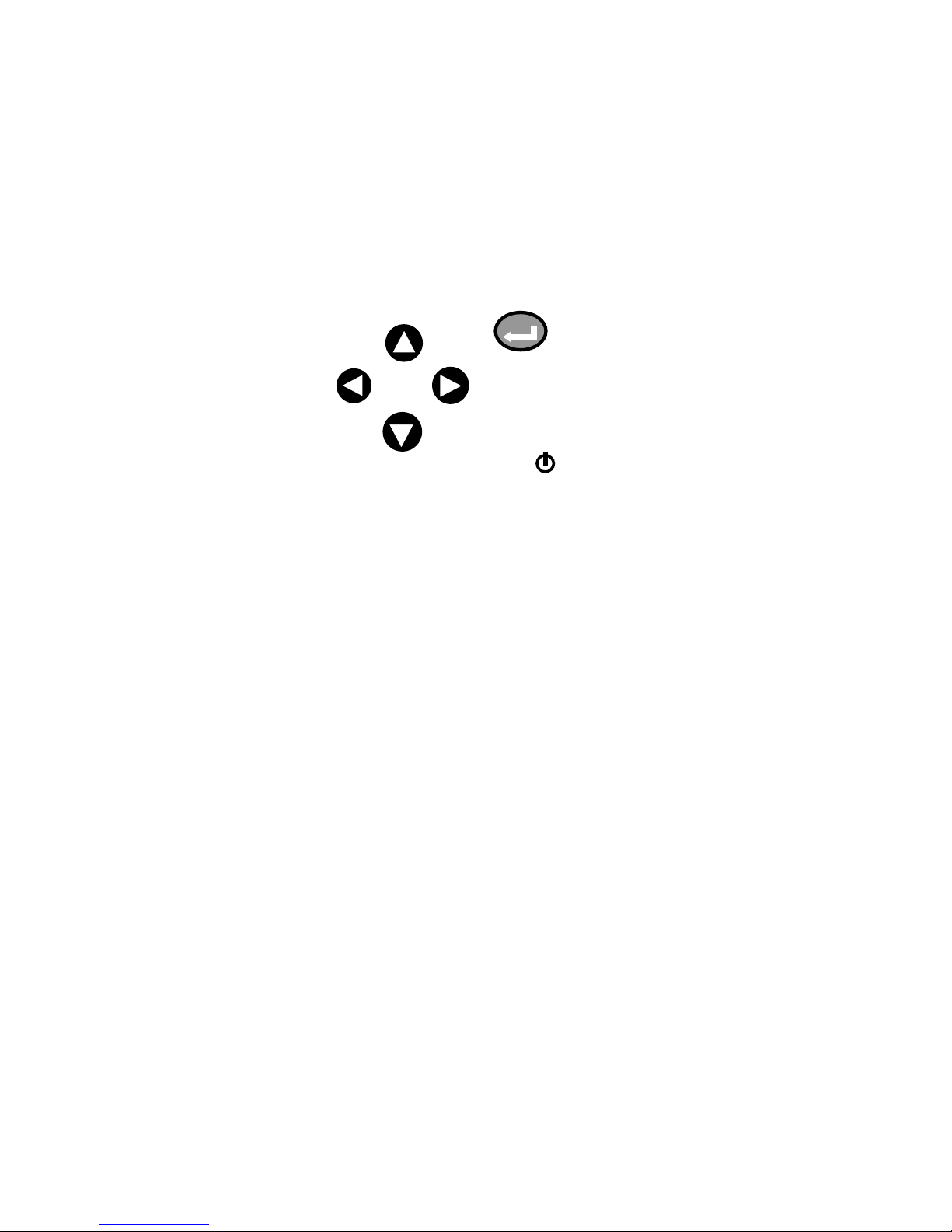
The ‘controls’ of the SENTRON pH meter are condensed to only six keys located on
the keypad.
The names ‘Power’, ‘Enter’ and ‘Arrow’ keys (‘Left’, ‘Right’, ‘Up’ and ‘Down’) will be
used consistently throughout this manual.
Figure 1: Keypad TITAN
After starting the meter by pressing ‘Power’, the display will briefly show the text
‘SENTRON integrated sensor technology’, the meter type (TITAN), the software
revision number and date, and the meter’s serial number. Then the Main menu as
described hereafter will be shown.
In the bottom left corner of the display an indication can read “ATT001” or another
number. This is quite normal and no cause for concern.
Warning ! As the system is not yet calibrated, the pH value shown in the display is
not reliable.
‘Up’
‘Power’
‘Down’
‘Enter’
‘Right’
‘Left’
‘Up’
SENTRON Europe BV Manual TITAN
Page 7 of 35
1.4.2. Display
The TITAN’s display is a graphics Liquid Crystal Display (LCD). The pH value can be
shown in 1 or 2 decimal resolution and temperature can be shown or be omitted. In
chapter 3 these settings are explained in detail.
Paragraph 7.1 describes how the display contrast can be set over a wide range,
allowing easy reading under virtually any ambient light conditions.
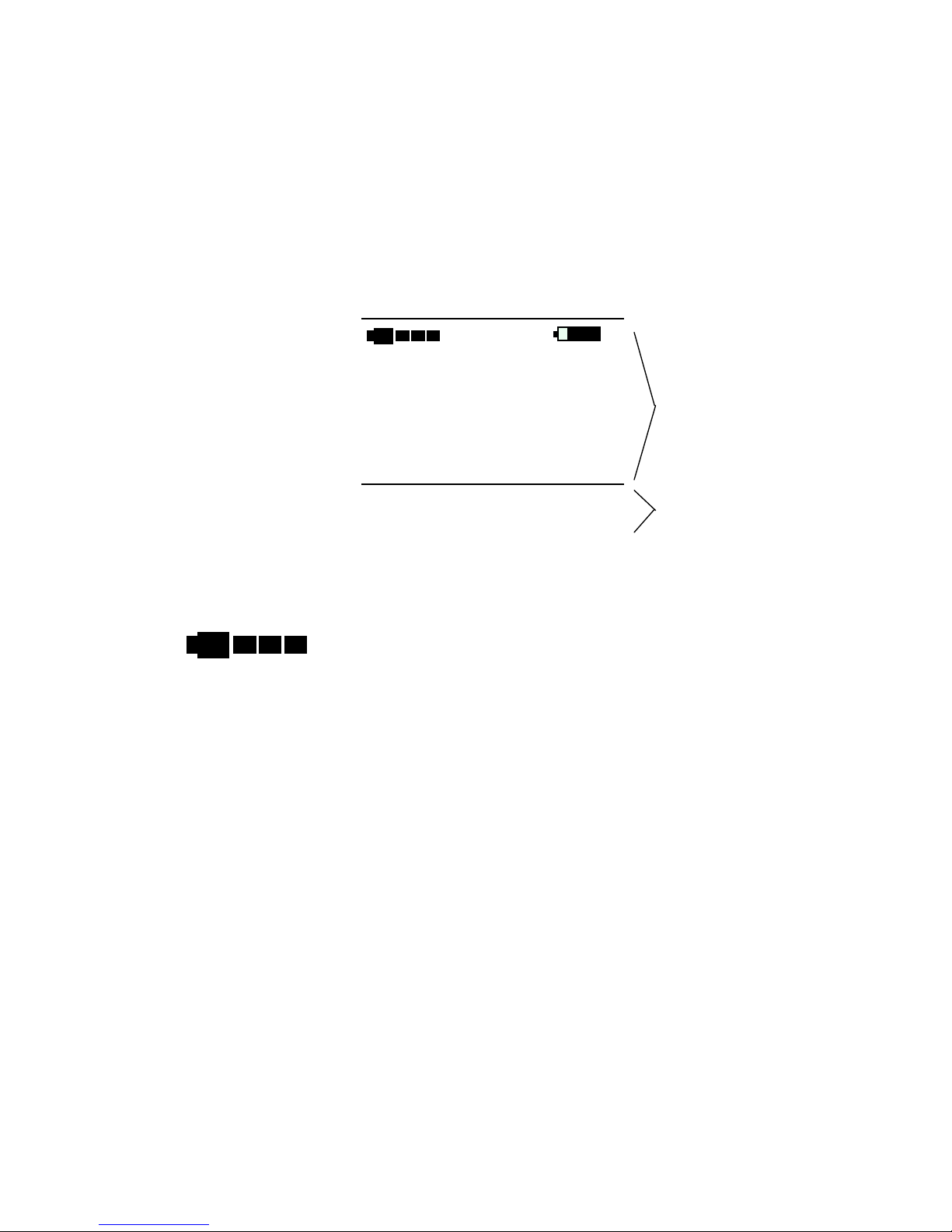
Figure 2 shows all possible contents of the display.
Figure 2: Possible display contents
The large section of the display shows following information:
Probe status indicator
Three blocks means that the probe gives maximum performance.
Two blocks means that the probe functions fine. Some maintenance (see cleaning
procedure, page 32) can bring it up to maximum performance.
In case two blocks are achieved by new probes, it is advised to place the probe-tip in
hand-warm water for 20 minutes, and then in buffer pH 4 for 1-2 hours. Recalibrate.
One block is typical for a probe that has been in use for some time.
The probe still gives accurate results, but may require cleaning by using water,
toothbrush and some mild detergent. Recalibrate using fresh buffers.
If none of the recommended remedial actions lead to probe status improvement, the
probe is near to the end of its functional life. Replacement will be necessary in the
near future.
pH value indication
These large digits represent the pH value
Temperature indication
12.34
pH
- 123.4 °C
Help Disp Calib
AutoR Store Config
AR
CAL
++
Low
Status indication text line
12.34
pH
Large section
Lower section
- 123.4 °C

SENTRON Europe BV Manual TITAN
Page 8 of 35
These smaller digits represent the actual temperature in oC/ºF, see paragraph 7.3.1.
Battery status indication
When the remaining operational time is less than approximately 5 hours, a “low”
indication will appear. When charging the battery, two alternating “+” symbols are
shown on the right hand side of the battery symbol.
The filling of the battery symbol indicates the actual battery status.
Autoread activated
When the Autoread function (automatic stability check) is activated, the text “AR” will
be shown in the display. Both the pH value and the “AR” symbol will blink when the
signal is not stable. When the pH measurement signal is within the stability limits, the
pH value and the “AR” symbol will be shown continuously, thus providing a clear
visual stability indication. Also refer to chapter 5.
Calibration indication
In the bottom left corner the text “CAL” will be blinking when calibration is in progress.
The status text line at the bottom of the middle section is used for a wide variety of
indications. Examples can be found throughout this manual.
Lower section menu items
In the lower section, the operating menu allows a
variety of choices. Use the ‘Arrow’ keys to go to the desired selection, then use the
‘Enter’-key to activate the highlighted function. The menu options shown here are
from the Main menu. Every sub-menu will show its own menu items.
++
Low
AR
CAL
Status indication text line
Help Disp Calib
AutoR Store Config
SENTRON Europe BV Manual TITAN
Page 9 of 35
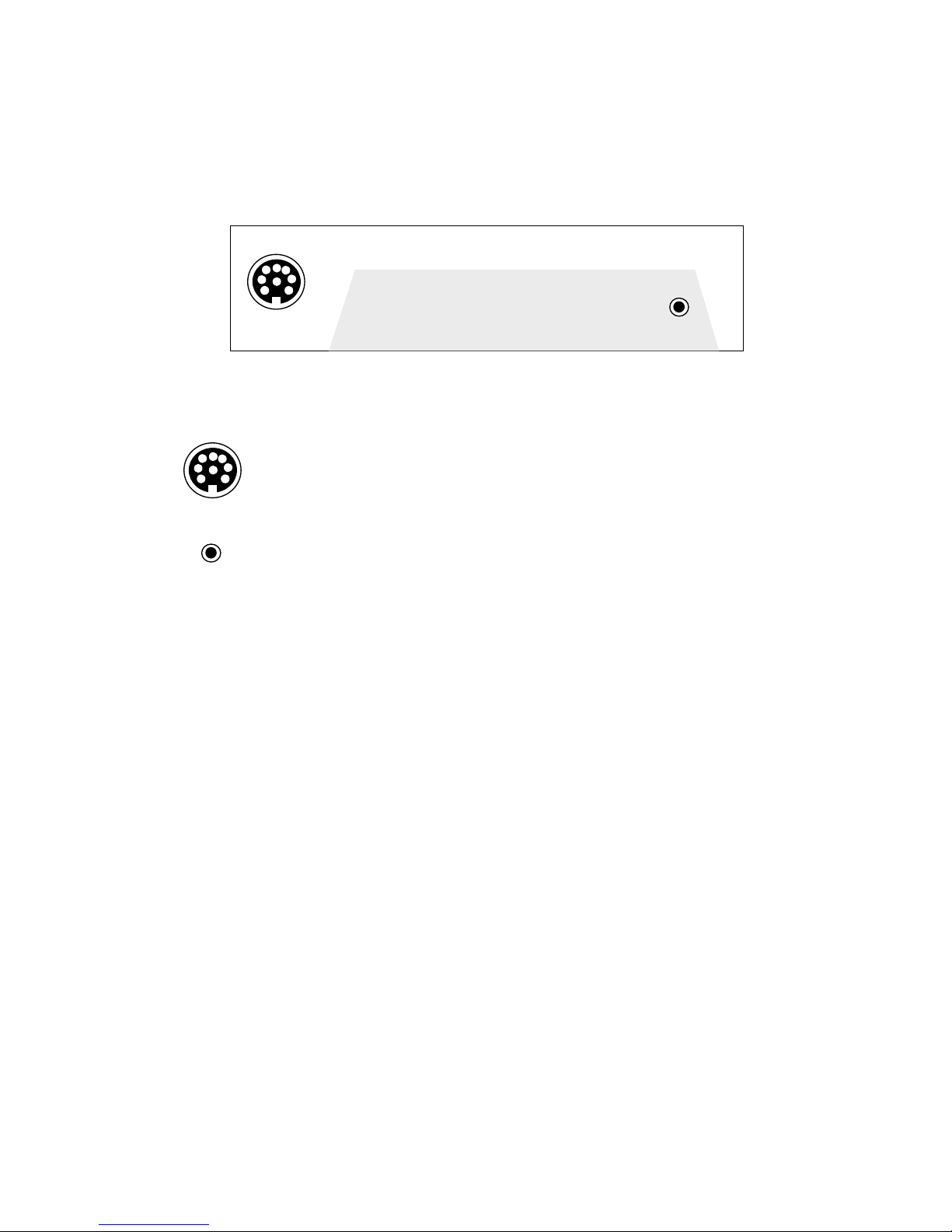
1.4.3. Connections
Physically different connections guarantee that it is impossible to fit connectors to the
wrong receptacle.
Connectors are placed on the backside of the TITAN meter as shown in figure 3.
Figure 3: Connectors available on TITAN
From left to right, following connectors are available:
Probe connector. This receptacle accepts the probe’s 8-pole male connector.
A physical insert allows only one possible connection.
After insertion, the connector needs to be screwed on
handtight by turning the sleeve clockwise.
AC Power supply. SENTRON provides adapters that transform wall-outlet AC
power to the level required by the TITAN meter. The meter
itself takes care of charging the internal battery.
See paragraph 1.4.4 for more information on battery
management.
1.4.4. Battery
The built-in battery is a rechargeable Nickel-Metal-Hydride (NiMH) battery. Before
shipment from SENTRON the battery is fully charged, but we suggest to connect to
AC power for at least 12 hours before relying only on battery power. Battery charging
is indicated in the display by a “++” sign on the right hand side of the battery symbol.
A fully charged battery will typically give 24 hours of use. The battery status is
constantly indicated in the display, and automatic ‘low’ battery warning is given when
the remaining battery life is approximately 5 hours.
Should the battery be completely exhausted during normal operation, it is still
possible to recharge the battery to its normal condition but it is advised that the
battery status indication is monitored by the user and that the battery is timely
recharged by connecting the meter to AC power.
Note Overcharging the battery is not possible and the applied NiMH-batteries do not
suffer from the so called “memory-effect”.
A prolonged exhausted battery may result in an automatic meter reset.
After recharging a completely exhausted battery, a user-reset may be required
to restart the meter. Please refer to paragraph 8.2.
First connect the meter to the mains, and only then switch it off. This allows a
visual check if the battery is charging correctly, indicated by the “++” signs
next to the battery symbol.

SENTRON Europe BV Manual TITAN
Page 10 of 35
2. HELP-Function
The TITAN meter is equipped with an elaborate on-board help function, designed to
provide to-the-point assistance.
The HELP function presents a situation dependant overview of the meter’s
functionality which will in most cases be sufficient for the user to continue operation.
If a situation occurs that requires the user to take actions (indicated by the text
“ATTxxx” on the display) the helptext will accurately describe the situation and what
remedy can be taken.
3. Display pH and Temperature
The TITAN meter is a highly sophisticated and accurate instrument, equipped with a
high quality graphic Liquid Crystal Display (LCD).
The pH value can be shown with either one- or two-decimal resolution, depending on
the calibration method, the user’s preference and the application demands.
The sample’s temperature is measured by a thermistor which is built into the tip of
the probe and provides fully Automatic Temperature Compensation (ATC). The
temperature can be indicated in the display.
Thus, the system offers four possible display settings:
- pH 0.1 without temperature indication
- pH 0.1 with temperature indication
- pH 0.01 without temperature indication
- pH 0.01 with temperature indication
To change between these settings, go to the Main menu. Use the ‘Arrow’ keys to go
to “Disp” and press ‘Enter’ repeatedly until the desired setting appears.
Note Because of the nature of a 1-point calibration, the accuracy is not sufficient for
a 0.01 pH indication. When selecting the 0.01 pH resolution indication after a
1-point calibration, the second decimal will blink to indicate that it is not to be
regarded as accurate. It is therefore advised to perform a calibration that
provides the accuracy required by the application, i.e. a 1-point calibration for
0.1 pH accuracy or a 2- or 3-point calibration for 0.01 pH accuracy.

SENTRON Europe BV Manual TITAN
Page 11 of 35
4. Calibration
To obtain reliable readings from the TITAN system it must first be calibrated, using
correct buffers, for maximum accuracy at the same temperature as the sample will
be.
The TITAN has four built-in tables of 5 buffers versus temperature. When performing
a calibration, the bufferset chosen is shown on the display. The built-in buffersets are
standardized DIN, JIS and NIST buffers and a SENTRON provided NIST traceable
bufferset.
Factory default, the SENTRON bufferset is selected. Please refer to paragraph 7.3.4
on selection of another bufferset.
The system automatically stores calibration results for later review.
Paragraph 7.3.6 provides all details on this function.
Warning ! Make sure that the buffers used during calibration are identical to the
selected bufferset, otherwise significant variations in measurement
values may occur.
Over time, the value from a buffer may change. Especially buffers with
values over pH 7.00 are susceptible for CO2 contamination.
Make sure that the buffers used for calibration are fresh, and not
contaminated by other materials.
SENTRON provides buffers in twin-neck bottles specially designed to
facilitate this use.
4.1. Performing a calibration
If the probe is newly connected to the meter (indicated by ATT021 on the status
text line), or if the meter has been switched off for several hours, it is
necessary to place the probe in a buffer solution, with the meter switched on,
for a period of 10 minutes. This initiating time allows the probe to set itself for
use after a period of inactivity and is required to ensure stable readings.
Rinse the probe before calibration.
The TITAN allows for various calibration methods. In general, the achievable
measurement accuracy over a certain pH range will increase when a more-point
calibration is performed.
During calibration, the “CAL” indication will blink in the display
After completing the calibration, the slope percentage is briefly displayed, except with
the 1-point calibration as no slope can be calculated there.
Instead, the last calculated slope is used.
 Loading...