

Sentrol ZX400,ZX410 Programming Manual

SENTROL ZX400/ZX410
Security System Control
Programming
1

2

Table of Contents
Operating the System .............................................................................................. 5
Introduction .............................................................................................................5
Powering Up With the Control Station......................................................................5
Control Stations ........................................................................................................6
Control Station Overview ..........................................................................................7
Control Station Function Keys ...................................................................................8
Secondary Function Keys ..........................................................................................8
Installer Arming and Disarming.................................................................................9
Installer On Premises.................................................................................................9
Trouble Conditions ...................................................................................................9
Testing ......................................................................................................................9
Programming the Control ..................................................................................... 10
Introduction ...........................................................................................................10
Local Programming.................................................................................................10
Remote Programming (RPM/2) ...............................................................................10
Area Partitioning .....................................................................................................10
LED Control Station Programming ..........................................................................12
TABLE OF CONTENTS
Installer Level Programming.................................................................................. 13
Menu Options.........................................................................................................13
Remote Connect ...........................................................................................13
Set Clock .......................................................................................................13
Edit Function Map .........................................................................................14
Entering a New Value At a Location ...............................................................14
Programming Account Code and Telephone Number Digits .........................15
Programming Report Codes and Attribute Fields...........................................15
Additional Programming Notes .....................................................................15
Programming Zone Names ...........................................................................15
Programming User Codes .............................................................................16
Restore Factory Defaults ................................................................................17
Days Until Next Comm Test ..........................................................................17
Call RPM ....................................................................................................... 17
Program RF Data ...........................................................................................18
Programming RF Zone Devices Into the RF Gateway ..........................18
Programming RF User Devices Into the RF Gateway............................19
Programming RF Devices Into the Control Panel.................................19
3

TABLE OF CONTENTS
Function Map .........................................................................................................20
Programming Notes ...............................................................................................50
Area Data Descriptions ..................................................................................20
Keypad Data Descriptions ............................................................................. 23
Zone Data Descriptions .................................................................................25
User Data Description ...................................................................................28
Authority Levels.............................................................................................29
Output Definitions Description......................................................................31
Bell Output Activation.........................................................................33
Programmable Output Activation .......................................................33
Global System Options Description ...............................................................35
Communicator Data Description ...................................................................37
Communication Numbers Description ..........................................................38
Dialed Digits Allowed..........................................................................39
Pager Telephone Numbers ..................................................................39
Event Reporting Description ..........................................................................40
Zone Report Codes Description.....................................................................42
User Report Codes Description ......................................................................44
System Report Codes Description..................................................................45
Area Schedules Description ...........................................................................47
Automatic Arming ..............................................................................47
Latch Key Schedules ...........................................................................47
Programming Options...................................................................................49
Digital Communicator Table For Contact ID Formats ........................................... 56
UL Programming Requirements ............................................................................ 59
Underwriters Laboratories (UL) Listing ....................................................................59
UL Notes In This Manual .........................................................................................59
UL Notes About Program Functions ........................................................................59
UL Notes About Zone Planning ...............................................................................60
4
Operating the System
READY
TROUBLE
OPERATING THE SYSTEM
Introduction
The Sentrol ZX400/ZX410 Security System incorporates the most desired operational features available
today. The ZX400/ZX410 features ease of installation
and programming with an easy-to-operate keypad.
Features such as cross-zoning, delay before dialing, and
an audibles “mute” function on the keypad help reduce false alarms.
The ZX400/ZX410 is pre-programmed at the factory
with one 2-wire smoke detector zone and twelve burglar zones (one delay, two interior, and nine instant)
through Sentrol’s unique “2 in 1” Zoning™.
A Zone Expander Module (ZXEXP) may be added to
provide an additional 2-wire smoke detector zone and
up to 16 additional zones. Up to 16 RF Points may be
used with the 4710 and 4720 RF Gateways.
The ZX400/ZX410 Security Control is easily programmed with any one of four Control Stations (LCD,
LED, SSD, or VFD). The Control’s on-board RAM maintains its data even with the power disconnected. The
Control may also be programmed remotely with the
aid of a personal computer (PC) and a modem using
Sentrol’s remote programming software (RPM2PRO)
and a panel support module (PRO400).
Powering Up With The Control
Station
The control comes from the manufacturer with a factory set (default) program. The factory default code
for user passcode No. 1 is “1234”. This passcode is
authorized to perform all user level functions. The
default setting for the installer passcode is “9632”. The
installer passcode can perform the installer level functions. (See Installer Level Programming - User Data
Description for the listed functions). All zones and Control Stations are assigned to Area 1 at default. The default setting for user passcode No. 50 is “1245” and it
is authorized to perform all user level functions. It is
assigned to both Area 1 and 2.
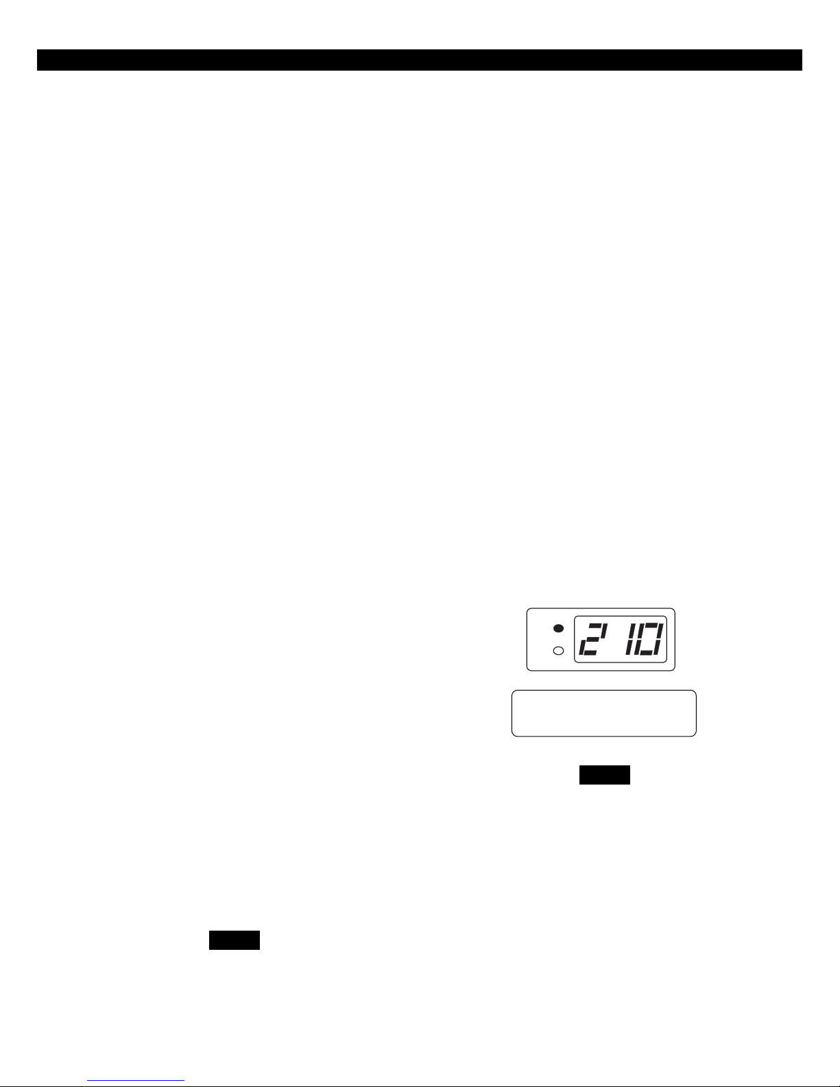
When a Control Station is powered-up, it briefly displays a test pattern followed by its data bus address.
The Control Station will then begin displaying information from the control panel. During the first fifteen
seconds after power-up, the control panel will instruct
the Control Station to display the panel’s software revision and flash the AWAY, STAY, NIGHT, READY, and
TROUBLE LEDs.
The ZX400/ZX410 Security Control allows the division
of a single system into two distinct areas, with an optional common area. To the customer, each area appears to be a fully functional system. The common
area appears to be an extension of both areas. Each
zone must be assigned to one of the two areas or to
the common area. Each Control Station must be assigned to one of the two areas and may be extended
to operate in the other area as a secondary area. The
common area is accessible to all Control Stations.
The Control may have up to 50 user codes. Each user
passcode must be assigned to one or both of the areas, and it must also be programmed with one of the
15 different levels of authority.
NOTE
Common Area is available in Rev 2.11
software and later revisions. Check
software version label or control panel
to determine revision level of soft-
ware.
PANEL REV 2.10
NOTE
Rev number may change as software
is upgraded.
5
OPERATING THE SYSTEM
AWAY
STAY
NIGHT
1
23
4
56
7
89
CLEAR
0
ENTER
VIEW INFO ALM MEM
EVENT LOG
BYPASS DELAY ARM CHIME
RST SMOKE TEST PROGRAM
QUIT ACCESS INSTANT
HOME NEXT
D
OFF
CANCEL
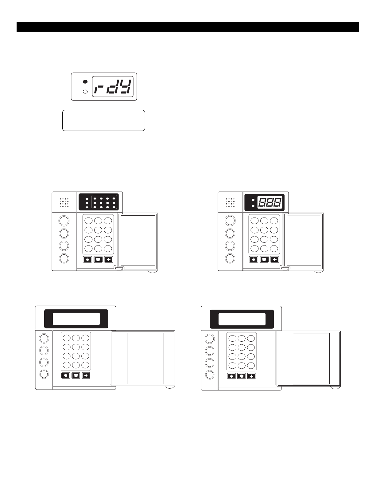
Once the zones are in a secure state, the Control
Station displays:
READY
TROUBLE
A1 READY TO ARM
JAN 21 05:27:52
Control Stations
1
234
READY
TROUBLE
5678
11 12109
EVENT LOG
23
DELAY ARM
56
89
ENTER
0
B
C
PREV
CANCEL
AWAY
STAY
NIGHT
FIRE
OFF
D
VIEW INFO ALM MEM
1
BYPASS CHIME
4
RST SMOKE TEST PROGRAM
7
QUIT ACCESS INSTANT
CLEAR
HOME NEXT
A
Nearly every option on the control requires the use
of a valid user passcode. The user passcode may be
used for functions in a specific area or system-wide.
Most of the options may be performed at any time,
even while the control is fully or partially armed. To
perform a function, a user must press the key corresponding to that function and then enter a passcode
with the appropriate authority level. For purposes
of discussion, the installer and the end user are both
considered system users, but have different levels of
authorization.
READY
TROUBLE
OFF
CANCEL
AWAY
STAY
NIGHT
D
VIEW INFO ALM MEM
RST SMOKE TEST PROGRAM
CLEAR
EVENT LOG
1
23
BYPASS DELAY ARM CHIME
4
56
7
89
QUIT ACCESS INSTANT
0
HOME NEXT
ENTER
LED Control Station
(ZXLED12)
EVENT LOG
CANCEL
AWAY
STAY
NIGHT
OFF
D
VIEW INFO ALM MEM
1
23
BYPASS DELAY ARM CHIME
4
56
RST SMOKE TEST PROGRAM
7
89
QUIT ACCESS INSTANT
CLEAR
0
HOME NEXT
ENTER
LCD Control Station
(ZXLCD)
SSD Control Station
(ZXSSD)
VFD Control Station
(ZXVFD)
FIGURE 1 System Control Stations
6

OPERATING THE SYSTEM
Control Station Overview
For SSD, LED, LCD, and VFD Control Stations:
Away, Stay, and Night Keys These keys, followed by a passcode, arm one or both areas to the
AWAY, STAY, or NIGHT level.
Away, Stay, and Night LED’s These LEDs backlight the AWAY, STAY, and NIGHT keys to indicate the
armed level of the Control Station’s primary area. These will flash
during Exit Time or during a Burglar Alarm after Dialer Delay has expired.
Off/Cancel Key This key, followed by a valid user code, disarms an area(s), silences
and cancels alarms, and silences trouble conditions.
Instant/Enter Key This key is used in programming to store entered data. Also, when
pressed during an exit time from a STAY or NIGHT arming, this key
disables both the entry and exit times for the primary area of the
Control Station.
Keypad Audibles The piezo resonator activates for conditions including entry and exit
notification, alarm, trouble, chime, etc.
Auxiliary Keys When enabled, these keys activate the auxiliary alarms (Fire, Police,
Clear/Quit Key This key is used to reset any entry error and to allow you to escape out
Keyboard Backlighting The Control Station contains recessed LEDs to provide a light in dark
For SSD and LED Control Stations only:
Ready LED This LED indicates the status of the Burglar zones assigned to the Con-
Trouble LED This LED will illuminate for system troubles (AC failure, low battery,
For LED Control Stations only:
Zone Status LED’s These LEDs generally indicate the condition of zones 1 through 12.
Medical Emergency) or call a pager.
of an operation. To clear a “Missing Keypad”, “Memory Error”, or
“Smoke Trouble” system trouble condition or to turn off the Duress
output, press and hold the CLEAR key for three seconds.
or dimly lit environments.
trol Station’s primary area. It illuminates when the Burglar zones are
all secure.
communication failure), zone troubles, and Burglar Tamper conditions.
(See Operating the System - Trouble Conditions for a complete list of
trouble conditions).
See the ZXLED8/ZXLED12 User Guide for how the LEDs indicate the
Normal, Faulted, Bypassed, Trouble, and Alarm conditions.
Fire Zone LED This LED indicates the status of the two-wire smoke zone on the main
For SSD Control Stations only:
Seven Segment Display The three Seven Segment Display (SSD) characters enunciate system
These LEDs may also display system trouble conditions and programming information.
control board (Zone 30).
status, zone status and user information. See the ZXSSD User Guide for
details.
7
OPERATING THE SYSTEM
Control Station Function Keys
All Control Station function keys (except the View
Info Key) require that the function key be pressed
followed by a valid passcode. The passcode’s authority level will determine if the selected function
can be performed. While entering the passcode,
there will be a four second time-out for no activity.
After the passcode has been entered, there will be a
three minute time-out for no activity. The time-out
will return the Control Station to idle. The operator
may press the CLEAR key at any time to return the
Control Station to idle.
Below are the functions associated with keys 0 - 9
and a brief description of the functions. For details
on the operation of these functions, as well as on
the three arming keys, see the appropriate User
Guide.
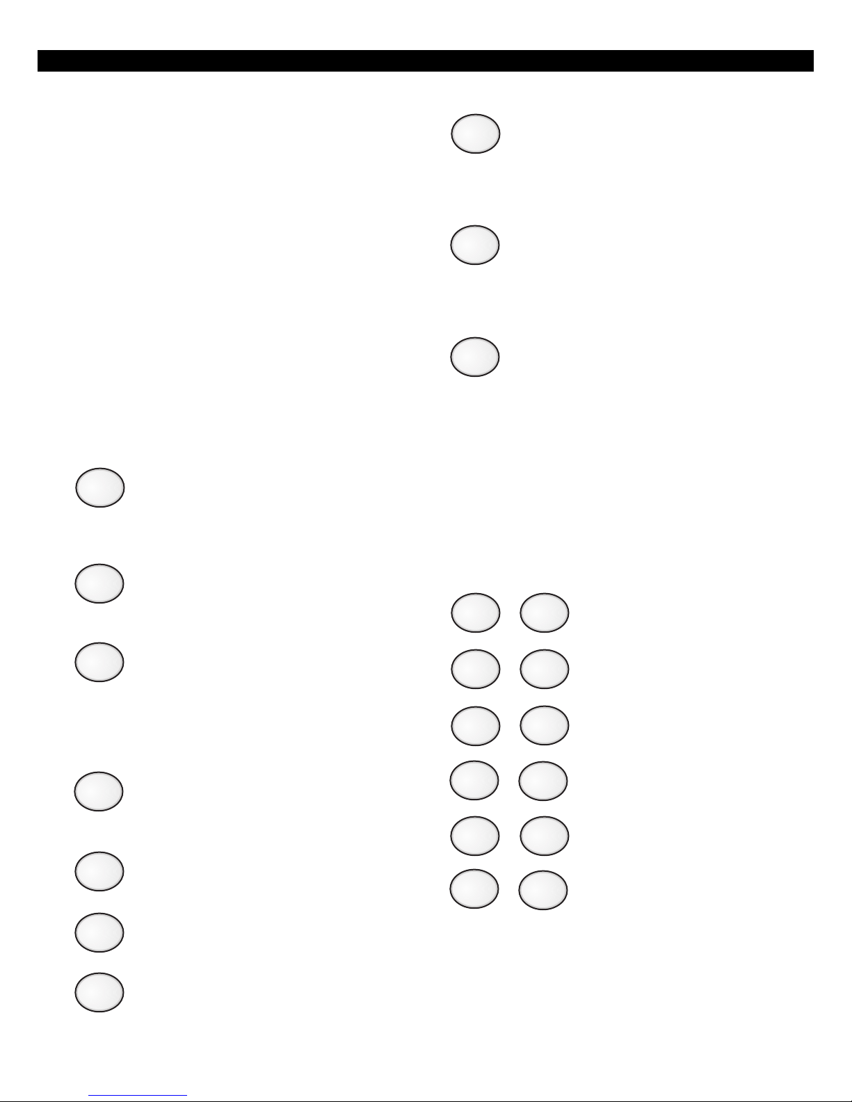
VIEW INFO KEY
1
2
3
This key is used to view information and
scroll through alarm and trouble conditions. A passcode is not required to perform this function.
ALM MEM KEY
This key allows you to view the most recent alarm event(s) on the Control Station.
EVENT LOG KEY
From an LED or SSD Control Station, this
key will initiate printing of the Event Log.
From an LCD or VFD Control Station, this
key will allow you to view the Event Log
on the Control Station or initiate printing the log.
8
9
0
TEST KEY
This key allows you to perform one of the
six following tests: Walk, Battery, Bell,
Communications, Keypad, and RF Signal
Strength. After a valid passcode is entered, you may select the test to perform.
PROGRAM KEY
This key is used to enter installer or user
level programming. User level programming is described in the appropriate User
Guide. Installer level programming is
described in Installer Level Programming.
ACCESS KEY
This key is used to activate a door strike
or other similar function.
Secondary Function Keys
The Control Station secondary function keys may
be activated by pressing the ENTER key followed by
Key #1 through Key #6. A passcode is not required
to activate these functions. These functions are activated by pressing the following:
ENTER
ENTER
ENTER
+ Turns Lamp Trigger Output
1
ON or OFF
+ Turns Universal Output ON or
2
OFF
+ Quick Access from Keypad
3
4
5
6
7
BYPASS KEY
This key allows you to select zones to be
bypassed (removed from the system) and
unbypassed (restored to the system).
DELAY ARM KEY
This key extends or postpones an automatic arming by one hour.
CHIME KEY
This key turns the chime function on or
off for a particular area.
RST SMOKE KEY
This key resets all latched smoked detectors and clears “Smoke Troubles” and
”Bell Silenced”.
ENTER
ENTER
ENTER
Please see Installer Level Programming - Output Definitions Description for more details on the operation
of these functions. The above outputs are only available to the user if you program them as Programmable
Outputs. If any of these features are made available to
the user, please instruct the user on their operation as
it is not detailed in the appropriate User Guide.
8
+ Turns Key 4 Output ON or OFF
4
+ Turns Key 5 Output ON or OFF
5
+ Turns Key 6 Output ON or OFF
6

OPERATING THE SYSTEM
Installer Arming and Disarming
The installer passcode may be used to arm one or
both areas. It may be used to disarm one or both
areas, but only if the area was armed by the installer
passcode. It may be used to silence alarms and to
silence trouble conditions. When it is used to silence a Burglar alarm, it will not disarm the area or
cancel the alarm unless the area was armed by the
installer passcode. For a detailed description of arming and disarming procedures, see the appropriate
User Guide.
Installer On Premises
When the installer passcode is used to program Function Map data or User Codes on the control panel or
RF Data on an RF Gateway, a “Local Program Begin”
event is logged to be reported. A “Local Program End”
event is logged to be reported 255 seconds after the
programming mode is exited or upon the CLEAR key
being pressed and held for three seconds.
Trouble Conditions
The possible trouble conditions are:
AC Power Failure Zone Trouble
Communication Failure Telco Line 1 Fault
Smoke Trouble RF Point Not Reporting
Missing Keypad Memory Error
Fire Trouble Supervisory Trouble
RF Jamming Silenced Burglar Tamper
RF Point Low Battery Zone Missing
Low/No Battery Bell 1 Fault
Silenced Fire Alarm RF Point Tampering
Call RPM Failed RF User Device Low Battery
Non-Telco Fault
Refer to the Installation manual for a description of these trouble
conditions.
Testing
The ZX400/ZX410 provides the following testing capabilities: Walk Test, Battery Test, Bell Test, Communicator Test, Keypad Test and RF Signal Strength Test.
Refer to the appropriate User Guide for instructions on
performing these tests. Always ensure that a Walk Test
(and an RF Signal Strength Test when applicable) is
performed on a new installation.
To test the Received Signal Strength of each RF Zone
Device, use Test 6 - RF Signal Strength Test. From
the Control Station press the “8” key, followed by
the Installer Code (9632) and then press the “6”
key. Next press the RF Zone Device Number (13 to
28). The Control Station will display and sound the
Received Signal Strength of the last transmission sent
by the RF Zone Device. See results below:
Strong Signal (HOT or 5 Control Station beeps):
a strong or high level RF signal was measured by the
receiver for that location of the transmitter. This is a
good location for the transmitter and receiver.
Acceptable (ACC or 3 Control Station beeps): a
normal or acceptable level of RF signal was measured by the receiver for that location of the transmitter. This is a good location for the transmitter
and receiver.
Low Signal (LOW or 1 Control Station beep): a low
not acceptable level of RF signal was measured by
or
the receiver for that location of the transmitter. Make
multiple test transmissions, making sure that obstructions between the transmitter and receiver are normal
but minimized (hands away from units, metal ladders
away from receiver, etc.) during these tests. The transmitter and/or receiver will need to be relocated to obtain ACCEPTABLE level readings.
No Signal (NO or 1 long Control Station beep):
no RF signal or an extremely low RF signal was measured by the receiver for that location of the transmitter. Bring the transmitter to the RF Gateway and
activate the transmitter. The red LED on the RF Gateway should blink. If it does not, then the transmitter
is not working. If the red LED does blink, but the
signal strength is still NO SIGNAL, then a programming error exists. Check the programming of the
zone in both the RF Gateway and the panel. If the
signal strength is STRONG or ACCEPTABLE, then the
transmitter and/or receiver will need to be relocated
to obtain ACCEPTABLE level readings. Be sure to
power down the control to clear out all signal
strength levels before testing the transmitter at its
new location.
After testing has been completed, the RF Gateway and
RF Zone Devices should be permanently mounted.
NOTE
Series 4000 RF Gateways and
transmitters which are not UL Labeled are not allowed in UL Certificated installations.
9

PROGRAMMING THE CONTROL
Programming the Control
Introduction
The control may be programmed locally from any
LED, SSD, LCD, or VFD Control Station. It may also
be programmed using the remote programming
software, RPM/2 Pro. Throughout this section, the
Fire Auxiliary key is referred to as the “A” key and
the Medical Auxiliary key is referred to as the “C”
key.
Local Programming
There are two levels of Control Station programming:
User level and Installer level.
User Level Programming
Provides the ability to add, change, or delete user
passcodes. It also allows Scheduled Arming and
Latch Key operation to be changed. A user passcode
with authority level 9, 10, or 15 is required to access
the user level programming (see Installer Level Programming - Authority Levels). See the appropriate
User Guide for more information regarding user level
programming.
Installer Level Programming
Allows total customization of the control’s operating features. Only the installer code may access this
level. Anyone attempting installer level programming should be familiar with the contents of this
publication prior to programming the control panel.
NOTE
If the installer code is lost or forgotten, it may be impossible to program
the control locally.
If remote programming is used, it is possible to “lockout” or prevent takeover of a control by another installation company by selecting “Lockout Local
Prog.” This prevents the installer passcode from
gaining access through local Control Station programming. The installer passcode may still be used
for the non-programming functions described in
Installer Level Programming - Authority Levels. Lock-
out Local Prog does not affect remote programming.
Remote Programming (RPM/2 Pro)
The entire control database can be programmed
remotely through a computer and modem using a
remote program called RPM/2 Pro. To use RPM/2
Pro with the ZX400/ZX410, you will need RPM2PRO
and a panel support module for the ZX400 family
(PRO400). Remote programming utilizes extensive
error checking and security safeguards, including
data encryption, password log-on, panel IDs and
agency codes.
Panel IDs are used by RPM/2 Pro to identify a control during a remote programming session. The
agency code is used by the control to identify the
remote programmer during initialization of a remote
programming session. These codes are loaded into
the control by RPM/2 Pro during the first RPM/2 Pro
session. They cannot be viewed by local programming.
The panel ID and agency code work together to prevent illegal takeover by another computer with RPM/2
Pro. Once the agency code is programmed, the
control also prevents local changing of account codes
and telephone numbers and disables the RESTORE
DEFAULTS function.
Area Partitioning
The control may be divided (partitioned) into two
independent areas. To the customer, each area appears to be a full-featured system. This allows one
control to be shared by two independent departments within a common structure.
NOTE
LED Control Stations cannot have a
Secondary Area.
Each area can be programmed to control separate
outputs with a dedicated audible or annunciator. It
is also possible to combine the outputs of both areas so that a central siren, bell or audible can be
used. The audible should be positioned so that it
can be heard by all partitions. When partitioning is
not desired, simply designate all zones to a single
area (Area 1).
10

PROGRAMMING THE CONTROL
An example of a partitioning application is a business that is divided into two departments with both
departments occupied by a different manager. The
control communicator would be installed in a secure area (common utility closet) with dedicated and
uninterrupted AC power and telephone service. This
must be considered when planning the control panel
position as the power and phone service to a tenant
may be terminated if that tenant leaves.
Each tenant’s compartment is assigned an area with a
number of zones, codes, and Control Stations. When
an area experiences an alarm or other event, the adjacent system area is not alerted to the event since the
Control Station would be programmed to respond only
to events in the assigned area (see Table 1).
Another programming feature is the ability to allow
crossover between areas. This allows the user(s) from
one area to operate the other area from a designated Control Station. Programming is discussed in
detail later in this manual. By factory default, users
are only allowed to see and operate their primary
assigned area. Multi-area operation may be useful
for applications where the security system is installed
in a facility that is divided into departments. Each
department has a set of users who are responsible
for arming and disarming only the security system
to which they are assigned. If desired, the system
may be set up to allow one or more users to have
control over both areas (see Table 2).
Another programming feature is common area burglar zones (see Operating the System - Introduction).
These zones may be used when a system needs to
be configured with two separate areas of protection
and a common area. For example, an office building with two separate offices and a common lobby.
The lobby (or common area) only gets armed when
both areas are armed in the AWAY mode. When one
area is armed in the AWAY mode, the common area
becomes an extension of the other area. When either area is disarmed, the common area also is disarmed. Faulted common area zones may be viewed
on all Control Stations.
Arming and disarming operations with a common
area are the same as without a common area, except that when an area is armed in the AWAY mode,
all common area zones may need to be secure.
Common area zones may not be force-armed, but
they may be bypassed. Common area zones may
be violated while either of the two areas is in Exit or
Entry time countdown.
Maximum Zones = 30
Up to 28 zones may be assigned to either area or
the common area (fire zones are system-wide and
have no area assignment).
Maximum Users = 50
Any number of users may be assigned to either or
both areas.
Maximum Supervised Control Stations = 6
SSD, LCD, and VFD Control Stations can be assigned
to operate in both areas if desired. LED Control Stations can only be assigned to operate in either Area
1 or Area 2.
When reporting to the Central Station, the control
has three sets of Account Numbers. One set for system events, one set for Area 1 events and one set for
Area 2 events. Examples of System events include:
Fire Alarms and Troubles, Common Area Burglar
Alarms, AC Power Failure, Low Battery and automatic
tests. Examples of Area 1 or Area 2 events include:
Burglar Alarms, Holdup Alarms, Opening/Closings.
All events are grouped into several categories with
each category having options of reporting to receiver
A, receiver B and/or a Pager.
11
PROGRAMMING THE CONTROL
SYSTEM AREA 1 AREA 2
System Account Numbers Area 1 Account Numbers Area 2 Account Numbers
Fire Zone 30 Burglar Zones 1 - 3 Burglar Zones 4 - 6
SYSTEM AREA 1 AREA 2
System Account Numbers Area 1 Account Numbers Area 2 Account Numbers
Common Burglar Zones 7 & 8 Burglar Zones 1 - 3 Burglar Zones 4 - 6
Fire Zone 30 Users 1 - 3, 7 Users 4 - 7
Table 2 Two Areas with Two Common Burglar Zones (Zones 7 & 8)
A Multi-Area User Code (User 7) and a Multi-Area Control Station (Keypad 5)
Users 1 - 3 Users 4 - 6
Control Stations 1 & 2 Control Stations 3 & 4
Table 1 Two Separate Areas
Control Stations 1, 2, 5 Control Stations 3 - 5
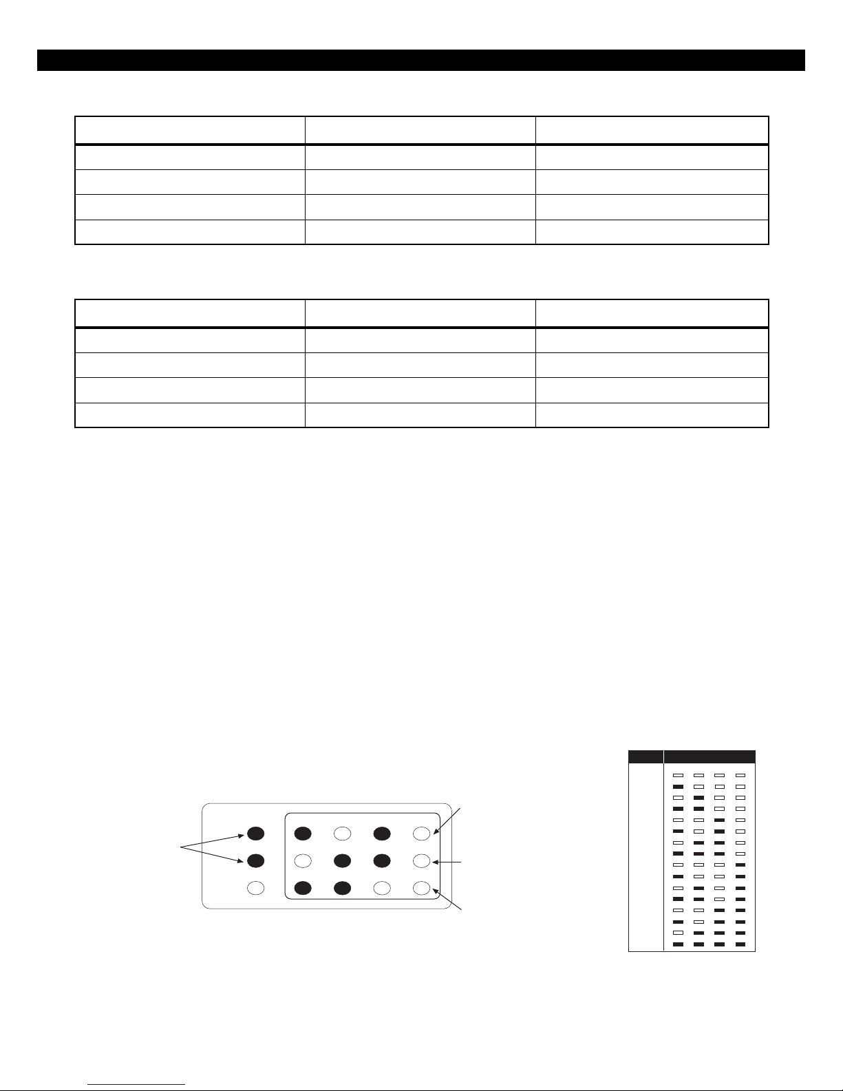
LED Control Station Programming
When in programming mode, an LED Control Station will mimic what is displayed on an SSD Control
Station. The top row of LEDs will correspond to the
first SSD character, the second row to the second
SSD character and the third row to the third SSD
character. If an SSD character is 1 - 9 or A - F, then
3
2
7
11
READY and
TROUBLE LEDs
Flash indicating that the
control is in programming
mode
READY
TROUBLE
FIRE
1
56
910
that hexadecimal digit will be displayed in binary
on the appropriate row of LEDs. See the Installer
Level Programming section for programming with
the Control Station. It will also show examples of
SSD, LCD, or VFD Control Station displays. There are
no examples for LED Control Stations (see Figure 2).
Value Display
1
0
1
2
3
4
5
6
7
8
9
10 (“A”)
11 (“B”)
12 (“C”)
13 (“D”)
14 (“E”)
15 (“F”)
12
ZONE LEDs (1 - 4)
Display hexadecimal value
4
8
corrresponding to left digit on SSD
Control Station (shown is '5')
ZONE LEDs (5 - 8)
Display hexadecimal value of
center digit (shown is '6')
ZONE LEDs (9 - 12)
Display hexadecimal value of
right digit (shown is '3')
2
8
4
Figure 2 LED Display
12
Installer Level Programming
INSTALLER LEVEL PROGRAMMING
Menu Options
This section will describe Installer Level Programming
as performed locally from a Control Station.
To enter Installer Level Programming, press the PROGRAM (9) key and enter the installer passcode (default = 9632). The Control Station will then prompt
you to select a programming option from 1 to 9
where:
1 = REMOTE CONNECT
2 = SET CLOCK
3 = EDIT FUNCTION MAP
4 = PROGRAMMING ZONE NAMES
5 = PROGRAMMING USER CODES
6 = RESTORE FACTORY DEFAULTS
7 = SET DAYS UNTIL NEXT COMM TEST
8 = CALL RPM
9 = PROGRAM RF DATA
Remote Connect
Press the ‘9’ key and enter the installer passcode to
enter programming mode. Press the ‘1’ key to perform a Remote Connect. The control will seize the
telephone line and the Control Station will return to
idle. This feature is used to manually connect the
control to a remote programming computer.
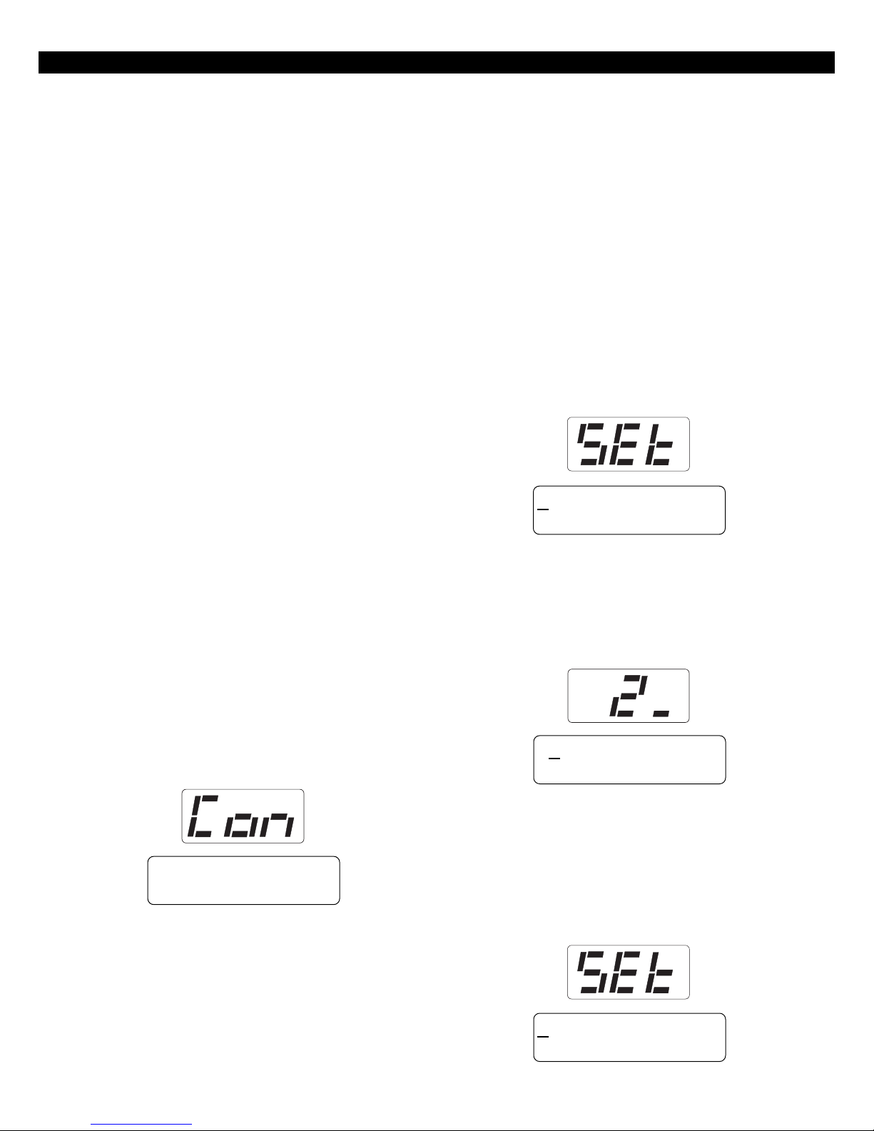
Set Clock
Press the ‘9’ key and enter the installer passcode to
enter programming mode. Press the ‘2’ key for Set
Clock programming. The Control Station will go
into clock set mode.
The SSD Control Station will have a Set Clock prompt
display. The LCD and VFD Control Station will display the current hour, minute, month, day, and year
(HH:MM MM/DD/YY). The zone LEDs on an LED
Control Station will remain off. The hour must be
entered in 24-hour format.
14:58 02/11/96
ENTER = COMPLETE
The operator may start entering numbers from the
first hour digit. As a number is entered, it is displayed and the cursor automatically moves to the
next position on the LCD and VFD Control Station.
When a digit is entered, the Control Station will display:
24:58 02/11/96
ENTER = COMPLETE
REMOTE CONNECT
If the CLEAR key is pressed, the cursor will move
back to the first hour digit and any changes that
were entered will be erased, i.e.: the current time
and date will be re-displayed. If the CLEAR key is
pressed and no changes have been entered, the
Control Station will return to idle with no changes
to the time or date.
14:58 02/11/96
ENTER = COMPLETE
13
INSTALLER LEVEL PROGRAMMING
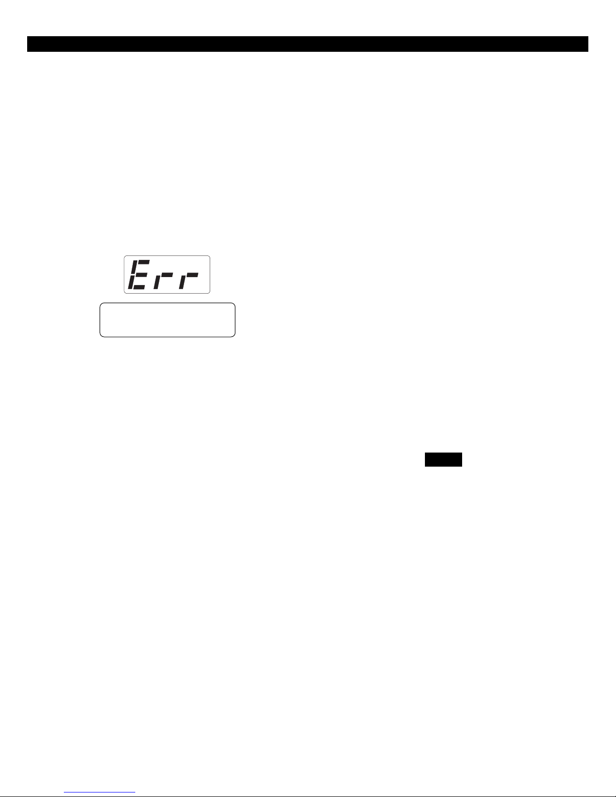
If the ENTER key is pressed, all changes that were
entered will be range checked. The entire time and
date need not be entered. Any fields that are not
entered will remain unchanged. If the data entered
is within range parameters, the clock will be updated
and the Control Station will return to idle. A “Begin
Set Clock” event will indicate the time before the
change and an “End Set Clock” event will indicate
the time after the change. If the entered data is out
of range, the Control Station will indicate an error,
erase the previous entries and re-display the current
time and date.
INVALID SETTING
Edit Function Map
Press the ‘9’ key and enter the installer passcode to
enter programming mode. Press the ‘3’ key to enter Edit Function Map mode. The Control Station
will prompt you for a location to be programmed.
The location numbers, definitions, and valid entries
for the locations are described in the Installer Level
Programming - Function Map section. From this
mode, you may edit the entire Function Map except for User Codes and Zone Names. Editing Zone
Names is described in the Installer Level Programming - Programming Zone Names section. Editing
User Codes is described in the Installer Level Programming - Programming User Codes section.
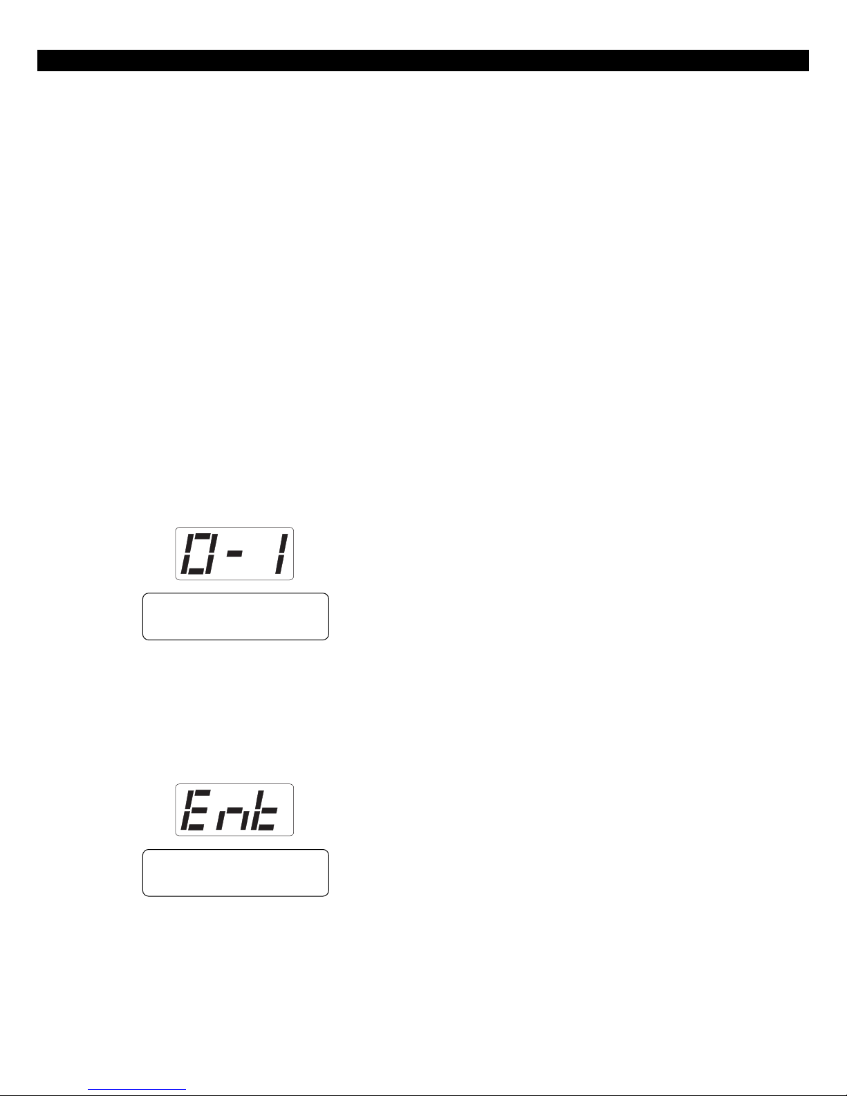
From the LOCATION prompt, enter digits for the
desired location number. The digits entered will be
displayed. If more than three digits are entered, the
first digit entered will be discarded. If you make a
mistake, you may press the CLEAR key to clear out
the location and start over. When the desired location number is displayed, press the ENTER key. The
Control Station will then display the current value
programmed at that location.
Entering a New Value at a Location
While the Control Station is displaying the value at a
location, you can enter digits to change the value at
that location. The new value is displayed as you
enter the digits. Other keys work as follows:
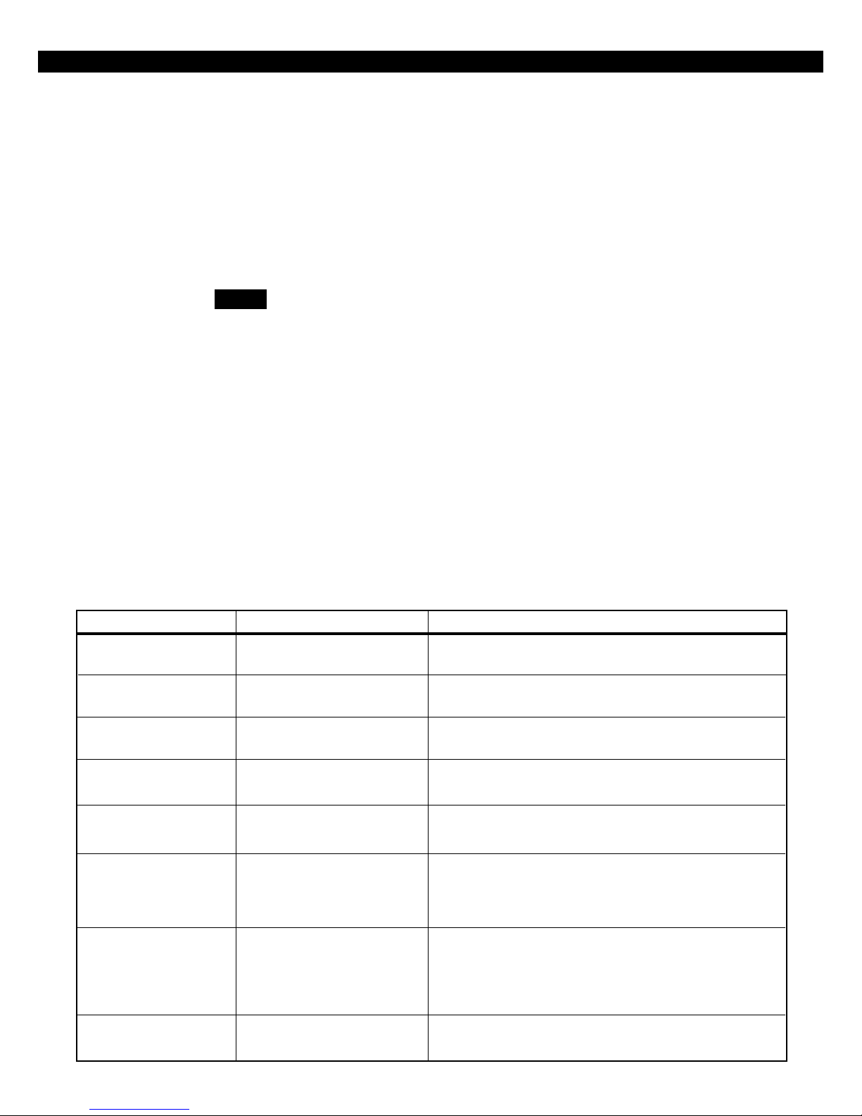
ENTER - if pressed after new digits are entered,
the displayed value is stored at the
current location.
- if pressed with no new digits entered,
then it will go to the next location.
‘C’ Key - if pressed, it will go back one loca-
tion and ignore any digits entered.
CLEAR - if pressed after new digits are entered,
the new digits will be erased and the
original value will be re-displayed at
the location.
- if pressed with no new digits entered,
then it will return to the LOCATION
prompt.
OFF CANCEL - on an LED or SSD Control Station, it
will momentarily display the present
location number.
NOTE
When you press the ENTER key to
store the new value, the system will
store the value as entered. It is the
responsibility of the programmer to
enter a value within the specified
range. If the value entered is out of
the range, then undesirable operation
may occur. In some cases, if the value
entered is too large, it will be truncated before it is stored causing a different value to be stored than was
entered.
14

INSTALLER LEVEL PROGRAMMING
Programming Account Code and
Telephone Number Digits
When the location being programmed is an account
code or telephone number digit (see Installer Level
Programming - Communication Telephone Numbers
Description and Area Event Reporting Description),
the value will be displayed as an “H” followed by a
single digit. The “H” indicates that this location is a
Hexadecimal field. The valid entries for these locations are “0” through “F”, where A - F correspond
to 10 - 15 respectively.
To program a digit, enter digits as normal. To enter
an A - F, enter a ‘1’ followed by a ‘0’ through ‘5’.
As in programming normal fields, if too many digits
are entered, the first digit entered will be discarded.
The ENTER, OFF CANCEL, ‘C’, and CLEAR keys will
work the same as described above.
Programming Report Codes and Attribute
Fields
As in programming normal fields, if too many digits
are entered, the first digit entered will be discarded.
The ENTER, OFF CANCEL, ‘C’, and CLEAR keys will
work the same as described above.
Additional Programming Notes
To exit out of Edit Function Map mode and return
the Control Station to the idle state, press the CLEAR
key from the LOCATION prompt. (You may need to
press the CLEAR key several times to get to the LOCATION prompt). An “End Local Programming”
event will not be logged until 255 seconds after you
exit programming mode. This is to allow you to
exit and re-enter programming mode repeatedly
without logging each one. To force an “End Local
Programming” event to be logged, immediately (i.e.:
to have it reported to the Central Station), press and
hold the CLEAR key for three seconds.
When programming the value at the last programming location, the Control Station will return to the
LOCATION prompt if the ENTER key is pressed.
When the location being programmed is a report
code (see Installer Level Programming - Zone Report Codes Description thru System Report Codes
Description) or an attribute field (see Installer Level
Programming - Area Data Descriptions thru Zone
Data Descriptions and System Report Codes Description thru Area Schedules Description), the value will
be displayed as an “H” followed by two digits. The
“H” indicates that this location is a Hexadecimal field.
The valid entries for these locations are “00” through
“FF”, where A - F correspond with 10 - 15 respectively. The Control Station display will automatically
display the hexadecimal value.
To program one of these locations, enter digits as
normal. To display a ‘1’ in the first digit location,
you must enter a ‘0’ before the ‘1’, i.e. ‘01’ displays
a ‘1’. To enter an A - F, enter a ‘1’ followed by a ‘0’
through ‘5’. For example:
Enter To Get
1-2-3 C3
0-1-2 12
1-8 18
0-1-1-0 1A
1-2 0C
2-1 21
If the panel has been programmed from RPM/2 Pro
and the Agency Code has been loaded into the panel,
then the locations corresponding to the telephone
numbers and account codes will not be editable.
Programming Zone Names
Only the LCD and VFD Control Station may be used
to program zone names. Press the ‘9’ key and enter
the installer passcode to enter programming mode.
Press the ‘4’ key to program the zone names. The
Control Station will prompt you for a Zone ID to be
programmed. The valid Zone IDs are 1 to 30.
Enter a number corresponding to the Zone ID and
press ENTER. Once a valid Zone ID is selected, the
control will display the Zone ID and the current Zone
Name with the cursor on the first character. Press
the key associated with each character. Each keypress
will change the display to the next character listed
for that key. The characters available for programming the Zone Names are located on the next page.
15

INSTALLER LEVEL PROGRAMMING
Key #1 0 1 2 3 4 5 6 7 8 9 : ; < = > ? @
Key #2 A B C
Key #3 D E F
Key #4 G H I
Key #5 J K L
Key #6 M N O
Key #7 P Q R S
Key #8 T U V
Key #9 W X Y Z [ ¥ ] ^ _
Key #0 space ! “ # $ % & ‘ * + , - . /
‘A’ Key Used to move the cursor back one position
‘C’ Key Used to move the cursor forward one position
If the ENTER or CLEAR key is pressed and no changes
have been made, the Control Station will return to
the Zone ID prompt. If the CLEAR key is pressed
and changes have been made, all changes will be
cleared and the Control Station will return to displaying the original Zone Name. To save any changes
made to the Zone Name, press the ENTER key. The
Control Station will return to the Zone ID prompt.
Press the CLEAR key to return to idle.
Programming User Codes
The installer passcode has the authority to program
user passcodes locally if Lockout Local Installer Programming is disabled. The control may be programmed with up to 50 user passcodes. See Installer
Level Programming - User Data Description for instructions on setting the authority level and area assignment for each passcode. To program or change
a user passcode:
1. Press the ‘9’ key and enter the installer passcode
to enter programming mode.
2. Press the ‘5’ key to Program User Codes. The
Control Station will prompt you to enter the User
ID of the passcode that you wish to program.
3. Enter the ID number and press the ENTER key.
4. Enter the new four-digit passcode. The Control
Station will beep twice and return to the User ID
prompt.
5. Enter a new ID number or press the CLEAR key
to exit.
The entire passcode is displayed on an LCD/VFD
Control Station. Only one digit at a time is displayed
on an SSD Control Station. To view the existing
passcode on an SSD Control Station, press the ENTER key after each digit is displayed.
If the new passcode being entered is a duplicate of
an existing one, the Control Station will sound an
error tone and return to the first digit location so
that you may try again. To make a User passcode
inoperable, enter “0000” as the new four-digit
passcode.
16
INSTALLER LEVEL PROGRAMMING
Restore Factory Defaults
This function provides a means to completely wipe
out the panel’s memory and restore it to a factory
default state. If successfully completed, the panel
will:
• default the entire Function Map (including Zone
Names and User Passcodes)
• clear the Event Log and log a “System Startup”
event
• clear all alarm, trouble and armed conditions
• not affect the System Clock (time and date)
• not affect data programmed in the RF Gateway(s)
If the panel has been programmed from RPM/2 Pro
and the Agency Code has been loaded into the panel,
then this function will be disabled.
Press the ‘9’ key and enter the installer passcode to
enter programming mode. Press the ‘6’ key to enter Restore Factory Defaults mode. The Control Station will prompt you to select the default mode.
ENT 0=STANDARD
1=COMM FIRE
Days Until Next Comm Test
The scheduling of Automatic Communications Tests
requires programming a “Comm Test Time-of-Day”
and the number of “Days Between Comm Tests” as
described in Installer Level Programming - Communicator Data Description. If “Days Between Comm
Tests” is zero, then no automatic comm tests will
occur. Otherwise, a comm test will occur when a
Days Until the Next Comm Test counter ticks down
to zero. This function allows you to view that Days
counter. If the value displayed is zero or one, then
the next comm test will occur at the next “Comm
Test Time-of-Day”. This function also allows you to
change the number of Days Until the Next Comm
Test.
Press the ‘9’ key and enter the installer passcode to
enter programming mode. Press the ‘7’ key to enter Days Until Next Comm Test programming. The
Control Station will display the number of days until
the next scheduled comm test.
To change this value, enter a number between 0
and 255. If a mistake is made, press the CLEAR key
to start over. If a number greater than 255 is entered, the first digit entered will be discarded. When
the desired number of days is displayed, press the
ENTER key. The Control Station will return to idle.
To exit out of this function without adjusting the
number of days, press the CLEAR key.
For a ZX400 or ZX410, enter 0. For a ZX440F, enter
1. To convert a ZX410 to a ZX440F with a ZXCFK
(Commercial Fire Kit), you must default the panel
with option 1. Once the default mode is selected,
the Control Station will prompt you to re-enter the
installer passcode for verification.
TO DEFAULT PANEL
ENTER PASSCODE
If it is entered correctly, the Control Station will go
back to the system powering up display.
Call RPM
This option is not available at this time.
17

INSTALLER LEVEL PROGRAMMING
Program RF Data
In order for an RF Zone Device or RF User Device to
be received by an RF Gateway, the address of the RF
Device must be programmed into the RF Gateway
(as described in the next two sections). The ZX400/
ZX410 can support up to 12 RF User Devices per RF
Gateway and up to 16 RF Zones. The 16 RF Zones
are programmed into the RF Gateways as devices
13-28 corresponding to zones 13-28. The 12 RF
User Devices are programmed into a RF Gateway as
devices 1-12 in any order (there is no correlation
between these devices and the Control Panel’s configuration data). The 4710 RF Gateway is restricted
to devices 13-20 for zones 13-20 and devices 1-6
for six RF User Devices.
Programming RF Zone Devices Into the RF
Gateway
Press the ‘9’ key and enter the installer passcode to
enter programming mode. Press the ‘9’ key to Program RF Data. The Control Station prompts you to
select an RF Gateway to program. Press ‘1’ or ‘2’.
The Control Station then prompts you to select an
RF Device to program.
Enter 13 thru 28 to select an RF Zone and press
ENTER. The Control Station displays the eight digits that are currently programmed in the RF Gateway for that zone. For each digit, you may program
a new value by pressing a digit key. The Control
Station will automatically move to the next digit.
To move to the next digit without changing the current digit, press the ENTER key.
The first digit to enter is the Supervision setting
where:
0 = Unsupervised
1 = 200 Seconds
2 = 1 Hour
3 = 4 Hours
4 = 24 Hours
The next seven digits to enter come directly off of a
label on the RF Device.
After the last digit is entered, the data is sent to the
RF Gateway and is confirmed and the Control Station returns to the RF Device selection prompt. If
the data is successfully loaded into the RF Gateway,
the Control Station beeps twice. If the RF Gateway
does not respond, the Control Station sounds an
error tone and briefly displays an error message.
Check the data bus connections to the RF Gateway.
If the 8 digit number entered for the RF Zone is already stored in the RF Gateway for another zone,
the Control Station sounds an error tone and briefly
displays a message indicating the duplicate zone.
From the RF Device prompt, select another RF Zone
Device or press the CLEAR key to return to the RF
Gateway prompt. From the RF Gateway prompt you
can switch to program the other RF Gateway (if applicable) or press the CLEAR key to exit.
One RF Zone Device may be programmed into both
RF Gateways, but it must be programmed into a different zone on each gateway. When programming
RF Zone Data into two RF Gateways, be sure to note
which zones are programmed into each RF Gateway. When the zones are then programmed into
the Control Panel, select the correct RF Gateway as
the Expansion Device for that zone.
Programming RF User Devices Into the RF
Gateway
Press the ‘9’ key and enter the installer passcode to
enter programming mode. Press the ‘9’ key to Program RF Data. The Control Station prompts you to
select an RF Gateway to program. Press ‘1’ or ‘2’.
The Control Station then prompts you to select an
RF Device to program.
Enter 1 thru 12 to select an RF User Device and press
ENTER. The Control Station displays the eight digits that are currently programmed in the RF Gateway for that device. For each digit, you may program a new value by pressing a digit key. The Control Station will automatically move to the next digit.
To move to the next digit without changing the current digit, press the ENTER key.
If you make a mistake while entering the eight digits, press the CLEAR key and the Control Station returns to the first digit.
The first digit to enter assigns the RF User Device to
a keypad. This is required to determine the area of
operation of the RF User Device and for the Access
function. Enter ‘1’ thru ‘6’ for a keypad assignment.
18

INSTALLER LEVEL PROGRAMMING
The second digit to enter defines the operation of
the key(s) on the RF User Device, where:
SEC KEY KEY KEY KEY
DIGIT A B C D
1 AWAY STAY NIGHT OFF/CANCEL
2 AWAY STAY ACCESS OFF/CANCEL
3 AWAY STAY PANIC/HOLDUP OFF/CANCEL
4 AWAY STAY AUX/MED OFF/CANCEL
5 AWAY STAY ENTER 4 OFF/CANCEL
6 AWAY PANIC/HOLDUP ENTER 4 OFF/CANCEL
7 STAY PANIC/HOLDUP ENTER 4 OFF/CANCEL
8 STAY PANIC/HOLDUP AUX/MED OFF/CANCEL
9 AWAY ENTER 4 ENTER 6 OFF/CANCEL
The next six digits to enter come directly off of a
label on the RF User Device.
If you make a mistake while entering the eight digits, press the CLEAR key and the Control Station returns to the first digit.
After the last digit is entered, the data is sent to the
RF Gateway and is confirmed and the Control Station returns to the RF Device selection prompt. If
the data is successfully loaded into the RF Gateway,
the Control Station beeps twice. If the RF Gateway
does not respond, the Control Station sounds an
error tone and briefly displays an error message.
Check the data bus connections to the RF Gateway.
If the 8 digit number entered for the RF User Device is
already stored in the RF Gateway for another device,
the Control Station sounds an error tone and briefly
displays a message indicating the duplicate device.
From the RF Device prompt, select another RF User
Device or press the CLEAR key to return to the RF
Gateway prompt. From the RF Gateway prompt you
can switch to program the other RF Gateway (if applicable) or press the CLEAR key to exit. In most
cases, you can program an RF User device into both
RF Gateways.
Programming RF Devices Into the Control Panel
After the RF Devices have been programmed into
the RF Gateway, they must also be programmed in
the Control Panel. The programming options for the
Control Panel’s Function Map are described in Installer Level Programming - Function Map. When
RF Devices are used in an installation, be sure to consider the following:
For an RF Zone Device, the zone data described in
Installer Level Programming - Zone Data Descriptions must be programmed for the selected zone.
The Zone Type, Area Number and Burglar Zone Attributes locations are programmed as usual. The
Expansion Device location must be set to the appropriate RF Gateway for the zone. The first digit of
Zone Attributes location doesn’t need to be programmed because it is ignored for Wireless Zones,
but the second digit must be programmed as usual.
For an RF User Device, a user passcode must be created that consists of the last four digits of the RF
Device’s address (see Installer Level Programming Programming User Codes). An appropriate authority level and area assignment must also be programmed for that user (see Installer Level Programming - User Data Description). It is also required that
either the area assignment of the user passcode or
the area assignment of the associated keypad must
be a single area (i.e. an RF User Device on an RF
Gateway can only operate on one area). An RF User
Device can be programmed into two RF Gateways
with different keypad assignments on each. If the
device’s passcode is operational in both areas and
the keypad on one RF Gateway is operational in one
area and the keypad on the other RF Gateway is
operational on the other area, then the RF User Device can operate on either area depending on which
RF Gateway detects it.
NOTENOTE
For UL 1637 Home Health Care, RF
User Devices may only be assigned
to user passcodes 1-30.
19
INSTALLER LEVEL PROGRAMMING
Function Map
To edit the Function Map, press the PROGRAM (9)
key, enter the installer passcode, and press the ‘3’
key to select the Edit Function Map programming
option. The Control Station will prompt for a location to be programmed. All function map locations
can be programmed except for user codes and zone
names.
NOTE
When entering values into the programming locations, it is possible to
enter values which exceed the valid
range of the programmed options. It
is the responsibility of the installer to
ensure the correct value of any entry
programmed into the control. The
valid entries for each location are detailed in the following sections.
Area Data Descriptions
The following table refers to programming locations
1 through 20.
ITEM VALID RANGE DESCRIPTION
AWAY Exit Delay Time 0 to 255 seconds
STAY & NIGHT Exit Time 0 to 255 seconds
Entry Delay Time 1 0 to 255 seconds
Entry Delay Time 2 0 to 255 seconds
Pre-Alarm Warning Time 0 to 255 seconds
Panic Key Alarms 00 to 33
(see the Panic Key Table)
Closing Ringback 0 = Ringback Output
1 = Ringback Output and
Keypads
2 = Ringback Output, Bell
Output and Keypads
Time in seconds for all Burglar zones, may be audibly annunciated. (See Inst. Level Prog. - Prog. Notes, Note 1).
Time in seconds for all Burglar zones, always silent.
Time in seconds to enter Burglar zones defined as Delay #1, may be
audibly annunciated. (See Inst. Level Prog. - Prog. Notes, Note 1A).
Time in seconds to enter Burglar zones defined as Delay #2, may
be audibly annunciated.
Time in seconds to correct a false alarm, always audible.
(See Inst. Level Prog. - Prog. Notes, Note 2).
The first digit defines the annunciation of an alarm activated by
the Police key. The second digit defines the annunciation of an
alarm activated by the Medical/Emergency key. Either key may
also be used to initiate a call to a pager.
Determines how the system annunciates the successful transmission of an AWAY closing report to the Central Station.
Burglar Audible Lockout 0 = No Lockout
1 to 15 = Alarms for an Area
Determines the number of times that a Bell Output may be activated during an armed cycle, resets with disarm.
20
 Loading...