

Sentrol ZX400, ZX410 Installation Manual

SENTROL ZX400/ZX410
Security System Control
Installation
1

2

Table of Contents
New Features............................................................................................................. 5
ZX400/ZX410 Wiring Diagrams................................................................................ 6
ZX400/ZX410 Terminal Descriptions........................................................................ 8
“2 in 1” Zoning™ ...................................................................................................... 9
Conventional Methods of Wiring ........................................................................... 11
Class ‘B’ End-Of-Line Resistor Supervised Zones ..................................................... 11
Non-Supervised Closed Circuit Loop (No EOL Resistor Supervision) ...................... 11
Control Station Addressing and Supervision ......................................................... 12
SSD, LCD, and VFD Control Stations ...................................................................... 12
LED Control Stations .............................................................................................. 12
TABLE OF CONTENTS
Control Station Troubleshooting ............................................................................ 13
Clearing Trouble Messages ..................................................................................... 13
12 VDC Outputs ...................................................................................................... 14
Additional Outputs.................................................................................................. 14
Expansion Zones ..................................................................................................... 16
ZXEXP Zone Expander Module............................................................................... 17
Installation ............................................................................................................. 17
Wireless Devices ...................................................................................................... 18
Fire Zone Modules .................................................................................................. 19
ZEM Zone Expansion Module ................................................................................ 19
ZRM Zone Relay Module ........................................................................................ 21
ZXCFK Fire Module Kit ........................................................................................... 21
Power Issues ............................................................................................................ 22
Optional Battery Configurations ............................................................................. 22
ZX400/ZX410 Power Worksheet ............................................................................ 22
Auxiliary Power Supply Installation ......................................................................... 23
ZXPTR Printer Interface Module............................................................................. 24
3

TABLE OF CONTENTS
Specifications And Features .................................................................................... 25
Control Board ........................................................................................................ 25
Power Supply ......................................................................................................... 25
Recommended Battery ........................................................................................... 25
Recommended Transformer ................................................................................... 25
Enclosure................................................................................................................ 25
Digital Communicator............................................................................................ 25
Control Stations ..................................................................................................... 26
ZXLCD Control Station........................................................................................... 26
ZXVFD Control Station ........................................................................................... 26
ZXLED12 Control Station ....................................................................................... 26
ZXSSD Control Station ........................................................................................... 26
Optional Accessories .............................................................................................. 26
Output Provisions ................................................................................................... 27
List Of Compatible Accessories ............................................................................... 28
ESL Two-Wire Smoke Detectors .............................................................................. 28
ESL Four-Wire Smoke Detectors.............................................................................. 28
System Sensors Two-Wire Smoke Detectors............................................................ 28
System Sensors Four-Wire Smoke Detectors ........................................................... 28
Wheelock ............................................................................................................... 28
Compatible Central Station Receivers ..................................................................... 28
Agency Requirements ............................................................................................. 29
UL and ULC Listings ............................................................................................... 30
National Fire Protection Association (NFPA) Rules ................................................ 31
Smoke Detector Locations ...................................................................................... 31
Testing ................................................................................................................... 31
System Troubleshooting ......................................................................................... 32
FCC Compliance ...................................................................................................... 34
4

New Features
• 12 Zones with Sentrol’s unique “2 in 1” Zoning™
• Plus one 2-wire fire zone
• Expandable to 28 zones, plus two 2-wire fire zones
• Integrated Sentrol Series 4000 Wireless
• Two truly independent partitions
• Up to 50 user codes with 15 levels of authority
• 75 event log
• Four interchangeable Control Stations to choose from
• Customized scheduling with special supervisory report
• Ideal for residential, commercial, and industrial applications
• Control Station programming in less than 2 minutes with factory defaults
NEW FEATURES
The Sentrol ZX400/ZX410 Security Control features
ease of installation and programming. The ZX400/
ZX410 is easily programmed with any one of four
Control Stations (LCD, LED, SSD, or VFD). The control may also be programmed remotely with the aid
of a personal computer (PC) and a modem using
Sentrol’s remote programming software (RPM2PRO)
and a panel support module (PRO400). The Control
Stations are easy-to-operate and contain features
such as cross-zoning, delay-before-dialing and an
audibles “mute” function to help reduce false alarms.
The ZX400/ZX410 Security Control is pre-programmed from the factory with twelve burglar zones
(one delay, two interior, and nine instant) and one
2-wire smoke detector zone to allow for out-of-box
power-up and operation. The twelve burglar zones
have been configured in a ‘paralleled’ condition using Sentrol’s unique “2 in 1” Zoning™. A zone expander may be added to provide an additional 2wire smoke detector zone and, with the use of “2 in
1” Zoning™, up to 16 additional zones.
Sentrol Series 4000 RF Gateway receivers and sensors allow you to overcome installation obstacles and
increase profit potential. The wireless sensors have
been engineered for long term stability and reliabil-
ity. Using the Series 4000 Wireless System, you can
expand the ZX400/ZX410 to include up to 16 wireless zones.
The Control’s on-board RAM maintains its data even
with the power disconnected. A “Watchdog” timer
monitors the microprocessor to ensure the operational integrity of the system. The ZX400/ZX410
Control Board is equipped with one low current programmable output (PGO1) and one high current bell
output (BELL) which may be used for Fire, Burglar,
Auxiliary and/or Holdup alarms. In addition, two
ZXODMs (Output Driver Modules) can be added to
provide 20 more programmable low current outputs which may be used to trigger other devices.
The ZX400 Security Control may be purchased in
the ZX410 pre-configured package assembly. This
assembly incorporates the ZX400 Control Board
mounted inside a larger 14" x 14" x 3.5" enclosure,
EX1414. The ZX410 must be purchased for Commercial and Industrial UL Listed applications. For UL
Listed Commercial Fire applications, the ZX440F is
available. It consists of the ZX400 Control Board in
a red EX1414 enclosure, with a ZXCFM (Commercial Fire Module), a CR860 dual battery harness and
other cabling.
5
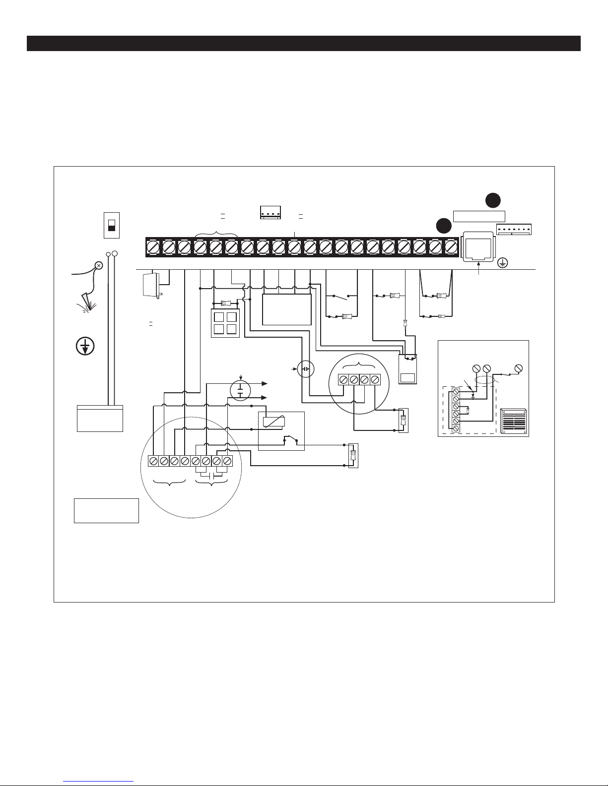
ZX400/ZX410 WIRING DIAGRAMS
ZX400/ZX410 Wiring Diagrams
J-3
7
6
NEG8DAT A
2WS
LISTED RATE OF RISE OR
FIXED TEMPERATURE THERMOSTAT
RED
BLACK
BROWN
9
DAT B10KP+1211NEG
GREEN
WHITE
CONTROL STATIONS
ZONE EXPANDER
PRINTER INTERFACE
ODMs
TO ANY ZONE DEFINED
AS 24-HOUR FIRE
POWER SUPERVISION UNIT
ESL MODEL 204-12/24V OR EQUIV.
Class II
PowerLimited
RED
BLACK
BROWN
Z1/7
12
13
Z2/814NEG
N.O.
N.C. ZONE 1
1500Ω
1/2 WATT
--
1500Ω (CR854)
(CONV ZONING)
GROUND
SCREW
Enclosure
Door
Ground
Wire
UNIFIED
EARTH
GROUND
Internally Fused.
Do Not Connect
Red and Black Leads RED = POS. (+) BLACK = NEG. (-)
12V SEALED
LEAD ACID BATTERY
Yuasa B-1270
FLOAT BATTERY VOLTAGE:
13.6 - 13.8V
Max. current: 500mA.
QUIESCENT CHARGE
CURRENT: 20mA.
Replacement: Every 3 - 5 years.
UL LISTED RESISTORS
MODEL CR853 - 825Ω E.O.L.
MODEL CR854 - 1500Ω E.O.L.
ON
OFF
1 2
~
AC XFMR
TRANSFORMER
Basler BE 116235
16.5VAC/35VA
U.L. Class II 50/60Hz
WARNING
Do Not Short.
To A Switched
Receptacle.
+--
+
POWER
SENTROL 4-WIRE MODELS
(See ZX400/ZX410 Interconnect Label
4
3
AUX125BELL
SW NEG
SIGNALING DEVICE
ALARM
CONTACTS
SMOKE DETECTOR
P/N 64600310-NOTE 2)
Class II
PowerLimited
1500Ω EOL
SUPERVISION
UL LISTED
Ademco AB12M
15
16
Z4/10
NEG
17
Z3/9
METHOD 1
ZONE 3
N.C.
1500Ω
1/2 WATT
ZONE 9
POWER
+
+
MOTION
DETECTOR
1500Ω (CR854)
(EOL DEVICE)
SMOKE DETECTOR
SENTROL 2-WIRE MODELS
(See ZX400/ZX410 Interconnect Label
P/N 64600310-NOTE 2)
825Ω
1/4 WATT
N.C.
18
Z5/11
I.C. Load Number 1
PG01
19
Z6/1220NEG
METHOD 2
ZONE 5
N.C.
1500Ω
1/2 WATT
ZONE 11
N.C.
825Ω
1/4 WATT
CONNECT
RJ31/33/45
CONNECTION OF UL COMMERCIAL
BURGLAR AUDIBLE
POLARIZATION AND
NOISE SUPPRESSION
DIODE
-
+
JUMPER
CORD
7
BELL
NEG
1500Ω (CR854)
(EOL DEVICE)
5
TEL
SUPV
J-10
J-4
13
Z2/8
ALL WIRING
BETWEEN CONTROL
& BELL MUST BE IN
CONDUIT.
ADEMCO AB12M
GRADE A BELL
COMMERCIAL
See Specification and Features section for a complete list of compatible accessories.
FIGURE 1 Suggested UL Household Burglar Alarm and/or Fire (ƒƒ) Alarm Hookup
6
ZX400/ZX410 WIRING DIAGRAMS
MPI-206
TEL
SUPV
INSTALL
JUMPER
TELEPHONE
SUPERVISION
TG - COM NC NO
CONNECTION
TG+
MPI-206
TG - COM NC NO
TG+
+12V NEG
TO TERMINAL 10
TO TERMINAL 20
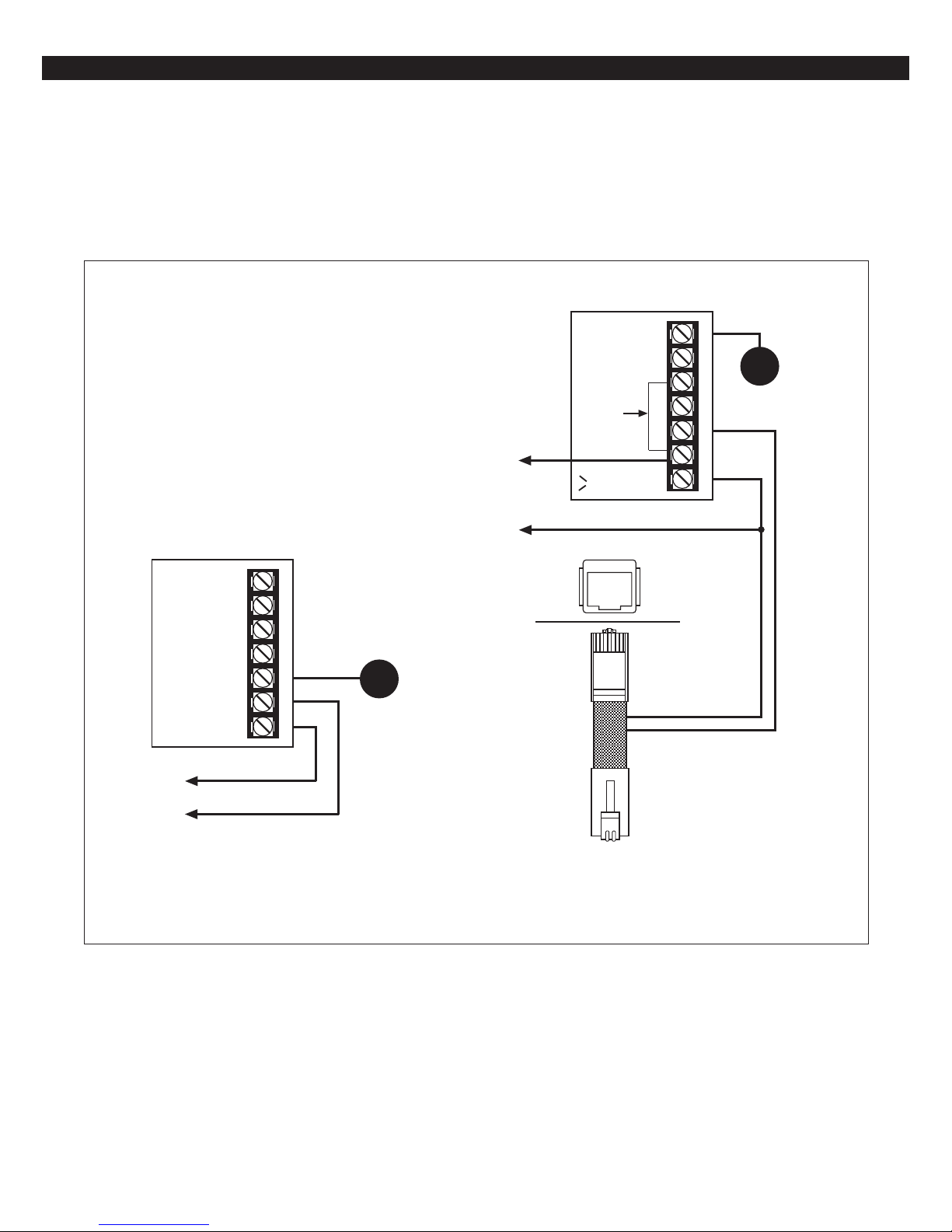
OPTIONAL - When relay is required
PROGRAMMABLE
OUTPUT 1
CONNECTION
PG01
TO TERMINAL 7
TO TERMINAL 4
CUT
JUMPER
J4
SENTROL RJ38 CORD
(shown)
OPTIONAL - When Telco Supervision is required
+12V NEG
ORANGE
BLUE
FIGURE 2 Programmable Output And Telco Supervision Wiring Diagram
7
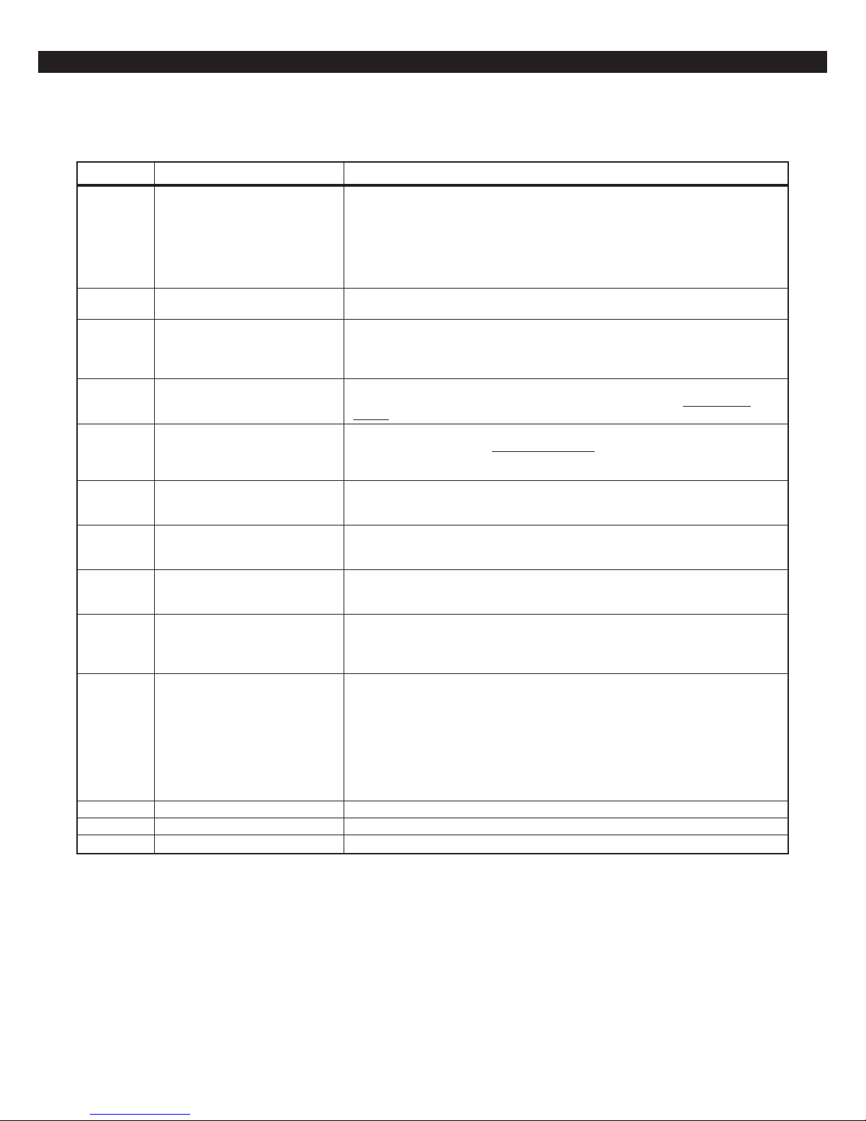
ZX400/ZX410 TERMINAL DESCRIPTIONS
ZX400/ZX410 Terminal Descriptions
TERMINAL FUNCTION DESCRIPTION
1, 2 AC Input Connect the appropriate UL Class II transformer using 18 gauge minimum 2
conductor wire. Do not exceed 50 feet. Use a 16.5 VAC 35 VA transformer or an
optional 16.5 VAC 20 VA transformer.
CAUTION: Do not short the terminals of the transformer together. This
causes the internal fuse to blow. The transformer must be connected to a
120 VAC, 24-hour outlet not controlled by a switch other than an approved
over-current protection device.
3 Switched Negative (-) Current limited 100 mA terminal. Negative connection for 4-wire smoke
4 Auxiliary Power (+)12 VDC 500 mA continuous power. Overcurrent protected at 1.35 amps
5 Supervised Bell Output (+)12 VDC. Combined alarm current should not exceed 1.5 amps. Overcurrent
(power-limited)
6 Two Wire Smoke (Zone 30) (+)12VDC of two-wire smoke detectors connected to this terminal. A 1500
(power-limited) Ohm EOL resistor (CR854) must be connected between terminals 6 and 7
7, 11 Common Negative BLACK WIRE - (-)12 VDC. Negative connection for Control Stations, zone
(power-limited)
8 Local Data Bus In (A) GREEN WIRE - Connection for Control Stations, zone expander, printer
9 Local Data Bus Out (B) WHITE WIRE - Connection for Control Stations, zone expander, printer
10 Control Station Power RED WIRE - (+)12 VDC 500 mA continuous power connection for control
(power-limited)
12 Zone 1/7 Loop (+)
13 Zone 2/8 Loop (+)
14 Common Negative
15 Zone 3/9 Loop (+)
16 Zone 4/10 Loop (+)
17 Common Negative
18 Zone 5/11 Loop (+)
19 Zone 6/12 Loop (+)
20 Common Negative
PGO1 Programmable Output 1 Use PGO1 as a +12V, 40 mA programmable output (see Figure 2).
TEL SUPV Telephone Supervision Use TEL SUPV as a telephone line trouble input (see Figure 2).
J4 Telco Jack RJ-31X connection.
detectors, glass break detectors, and devices requiring resettable power.
(PTC4). Used for powering motion detectors, 4-wire smoke detectors, glass
break detectors, and other accessories.
CAUTION: Use terminals 4 and 10 when calculating total current drain.
protected at 1.85 amps (PTC2). A 1500 Ohm EOL resistor (CR854) must be connected between terminals 5 and 7; otherwise a bell output fault will occur.
regardless of whether a two-wire smoke detector is used or not. The maximum
series resistance is 60 Ohms.
expander, printer interface, RF Gateway, ODMs, 2-wire smoke detectors,
motion detectors, and other devices.
interface, RF Gateway and ODMs. Use 22 guage wire up to 1000 ft. Use 18
guage wire up to 2000 ft.
interface, RF Gateway and ODMs. Use 22 guage wire up to 1000 ft. Use 18
guage wire up to 2000 ft.
stations, zone expander, printer interface, RF Gateway and ODMs. Overcurrent
protected at 1.35 amps (PTC4).
CAUTION: Use terminals 4 and 10 when calculating total current drain.
Each loop requires a 1500 Ohm end-of-line resistor (P/N CR854) for the primary
zone, and an 825 Ohm end-of-line resistor (P/N CR853) for the secondary zone.
A common negative is shared among all zones. The need for end-of-line resistors
may be eliminated on all Burglar defined zones through programming. See
Figure 1 for “2 in 1” Zoning™ wiring examples.
8

Secondary Zone
825Ω 1/4W
1500Ω 1/2W
Primary Zone
“2 in 1” Zoning™
“2 in 1” Zoning
™
NOTE
If a Normally Open Device (i.e., 4-wire
smoke detector) is used with “2 in 1”
Zoning™, a short will occur across
both zone loops when that device
goes into alarm. It is recommended
that these types of devices be used
with Conventional Zone wiring only.
The Sentrol ZX400/ZX410 Security Control introduces an all new method of wiring zones that saves
both time and wire costs. “2 in 1” Zoning™ allows
the installer to wire two separate zones in parallel
into one set of terminals.
Each zone is uniquely identified by its end-of-line resistor. The Primary Zone (zones 1-6) in each terminal is identified by a 1500 Ohm EOL resistor. The
Secondary Zone (zones 7 - 12) is identified by an
825 Ohm EOL resistor. The Primary and Secondary
zones operate as two independent zones to provide
separate reporting, programming, and displays. Each
zone is fully programmable as described in the
ZX400/ZX410 Programming Manual. The zones are
for Form A, Form B, or Form C sensors. Maximum
total loop wire and contact resistance (not including EOL) must not exceed 100 Ohms for the loop
to function properly.
There are two methods of wiring for “2 in 1” Zoning™. Method 1 wires one zone loop back to the
control while a second zone loop is added in parallel
off the first. This method may be employed in system retrofits, system expansions, or just simply to
save wire cost and labor.
1500Ω 1/2W
Primary Zone
Method 2 wires two separate zone loops back into
one set of terminals. The panel recognizes each
loop independently because two different EOL resistor values are used to differentiate between the
Primary Zone (1500 Ohm 1/2 Watt) and the Secondary Zone (825 Ohm 1/4 Watt). This method
provides two zones with one set of terminals and is
ideal for pre-wire or already installed wiring.
Figure 4 “2 in 1” Zoning™ Wiring - Method 2
NOTE
The resistors in Figure 3 & 4 are 1%
values to maintain proper loop resistance values. If replacements are required, please refer to the manufacturer for correct replacements. The
1500 ohm resistor is color coded
Brown•Green•Black•Brown•Brown.
The 825 ohm resistor is color coded
Gray•Red•Green•Black•Brown.
All zones sense five different voltage levels enabling
one zone to act as two. Troubleshooting is simple
using just a voltmeter at the control. The control
monitors the voltage level across the zone and uses
the voltage levels in Table 1 to determine whether
the zone is normal, open, or shorted.
Secondary Zone
825Ω 1/4W
Figure 3 “2 in 1” Zoning™ Wiring - Method 1
9

“2 in 1” Zoning™
CONDITION NOMINAL LOOP RESISTANCE VOLTAGE READING
Primary Zone and Secondary Zone Infinite Ohms 5.24 - 8.25 V
Open Contacts; Loop Cut or Open
Secondary Zone Open Contact, 1500 Ohms 4.24 - 5.23 V
Primary Zone Normal
Primary Zone Open Contact, 825 Ohms 3.24 - 4.23 V
Secondary Zone Normal
Primary Zone and Secondary Zone 825 Ohms in parallel with 2.00 - 3.23 V
Normal 1500 Ohms = 532 Ohms
Primary Zone and Secondary Zone 0 Ohms 0 - 1.99 V
Shorted
TABLE 1 “2 in 1” Zoning™ Troubleshooting Chart
10
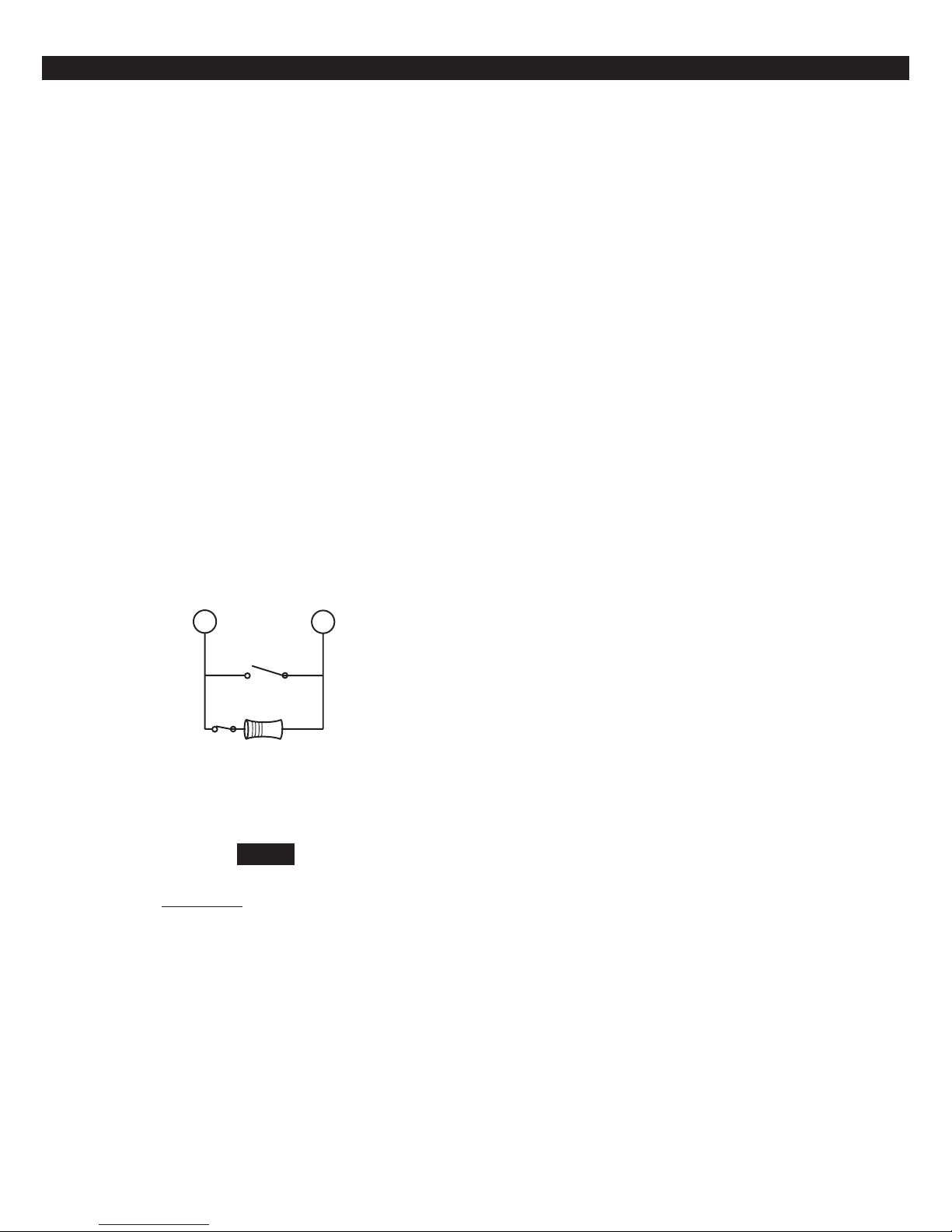
Conventional Methods of Wiring
CONVENTIONAL WIRING
Class ‘B’ End-Of-Line Resistor
Supervised Zones
A Class ‘B’ zone must be supervised with a 1500
Ohm 1/2 Watt end-of-line resistor (P/N CR854). This
resistor should be installed in series at the furthest
point from the control. This configuration must be
used whenever both Form A and Form B devices are
connected and provides a high degree of protection against compromise or tampering. The control
monitors the voltage level across the Primary zone
and uses the Primary zone voltage levels in Table 1
to determine whether the zone is normal, open, or
shorted. The operation of a zone is programmable
as described in the ZX400/ZX410 Programming
Manual. Maximum total loop wire and contact
resistance (not including EOLs) must not exceed
100 Ohms for the loop to function properly. The
1500 Ohm EOL resistor is optional for Form A connections but is required for Form B.
Normally
Open
Non-Supervised Closed Circuit
Loop (No EOL Resistor
Supervision)
The EOL resistor is not required on Burglar zones. A
conventional closed circuit loop may be connected
directly to a primary zone and the zone will have
either a short or an open condition. See the ZX400/
ZX410 Programming Manual for programming an unsupervised zone. Fire zones may not be installed as
unsupervised. Only Burglar defined zones may be
wired non-supervised. “2 in 1” Zoning™ is not
allowed.
1500Ω 1/2W
Primary Zone
Normally
Closed
Figure 5 Conventional Zone Wiring Method
NOTE
For UL Listed systems, EOL Supervi-
is required.
sion
11
 Loading...