

Sentrol ZX300, SENTROL ZX310 Installation & Programming

SENTROL ZX300/ZX310
Expandable Security System Control
Installation/
Programming
1

2

Table of Contents
ZX300/ZX310 Wiring Diagram......................................................................................5
Control Board T erminal Descriptions.........................................................................6
Zone Wiring.................................................................................................................... 7
Class ‘B’ End-Of-Line Resistor Supervised Zones ......................................................7
Non-Supervised Closed Circuit Loop (No EOL Resistor Supervision)........................7
ZXEX08 Zone Expander Module............................................................................. ... 7
Wireless Devices ..........................................................................................................8
Control Station Addressing and Supervision............................................................9
SSD, LCD, and VFD Control Stations......................................................................... 9
ICON Control Stations..................................................................................................9
LED Control Stations..............................................................................................9
Unsupervised and Supervised Control Stations..................................................... 9
T ABLE OF CONTENTS
Control Station Troubleshooting..............................................................................10
12 VDC Outputs .........................................................................................................11
Operating the System ................................................................................................13
Powering Up The Control ...........................................................................................13
Testing ...............................................................................................................13
Installer Arming and Disarming ..................................................................................13
Trouble Conditions .....................................................................................................1 3
Clearing Trouble Messages .......................................................................................13
Installer on Premises..................................................................................................13
Programming the Control.................................................................................................14
Introduction ...............................................................................................................14
Local Programming ....................................................................................................1 4
Programming Zone Names....................................................................................... 14
Installer Level Programming .....................................................................................15
Menu Options .............................................................................................................15
Program Function Map....................................................................................15
Entering a New Value at a Location................................................................15
Programming the Account Code and Telephone Number Digits....................16
Additional Programming Notes .......................................................................16
Program User Codes.......................................................................................16
Restore Factory Defaults ................................................................................16
Hours Until Next Comm Test...........................................................................1 7
Program RF Data............................................................................................17
Programming RF Zone Devices Into the RF Gateway ...................................17
Programming RF User Devices Into the RF Gateway....................................18
Programming RF Devices Into the Control Panel...........................................18
3

T ABLE OF CONTENTS
Specifications And Features .....................................................................................19
List of Compatible Accessories................................................................................22
SIA and Contact ID Formats......................................................................................23
Agency Requirements ...............................................................................................25
National Fire Protection Association (NFPA) Rules................................................27
FCC Compliance.........................................................................................................30
4

ZX300/ZX310 Wiring Diagram
WIRING DIAGRAM
7167-1459:114
FIGURE 1 Suggested UL Household Burglar Alarm and/or Fire (ƒƒ) Alarm Hookup
5
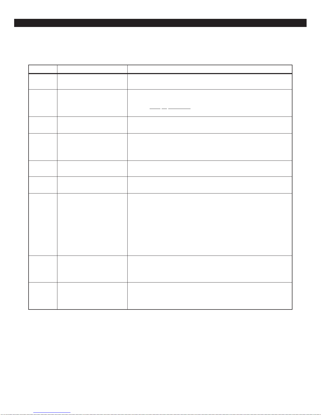
TERMINAL DESCRIPTIONS
Control Board Terminal Descriptions
TERMINAL FUNCTION DESCRIPTION
AC
BELL
NEG
KP+12V
GREEN
DAT A
WHITE
DAT A
NEG
Zone 1
Zone 2
Zone 3
Zone 4
NEG
Zone 5
Zone 6
NEG
Zone 7
Zone 8
AC Input
Supervised Bell Output
(power-limited)
Common Negative
Keypad Power
(power-limited)
Local Data Bus In
Local Data Bus Out
Zone Inputs
Connect a 16.5 VAC 15 VA UL Class II transformer minimum using 18 gauge
minimum 2 conductor wire. Do not exceed 50 feet.
(+)12 VDC. Combined alarm current should not exceed 1.0 amps.
Overcurrent protected at 1.35 amps (PTC2). A 1500 Ohm EOL resistor
(CR854)
a bell output fault will occur.
BLACK WIRE - (-)12 VDC. Negative connection for Control Stations, ODM,
RF receiver, zone expander, motion detectors, bell output, and other devices.
RED WIRE - (+)12 VDC 500 mA continuous power connection for Control
Stations, ODM, zone expander, and RF Gateway. Overcurrent protected at
1.35 amps (PTC1). CAUTION: Use the KP+12V and the +12V AUX
terminals when calculating total current drain.
GREEN WIRE - Connection for Control Stations, zone expander, ODM and RF
receiver. Use 22 gauge wire up to 1000 ft. Use 18 gauge wire up to 2000 ft.
WHITE WIRE - Connection for Control Stations, zone expander, ODM and RF
receiver. Use 22 gauge wire up to 1000 ft. Use 18 gauge wire up to 2000 ft.
Each loop requires a 1500 Ohm end-of-line resistor (P/N CR854). A common
negative is shared among all zones. The need for end-of-line resistors may be
eliminated on all Burglar defined zones through programming.
must be connected between the Bell and Neg terminals; otherwise
2WS
+12V AUX
Two-Wire
Smoke Terminal
Auxiliary Power
(power-limited)
Current limited 100 mA terminal. Connection for two-wire/four-wire smoke
detectors, glass break detectors, and devices requiring resettable power. The
maximum series loop resistance for a two-wire smoke loop is 20 ohms. The
maximum Alarm Impedance is 500 ohms.
(+)12 VDC 500 mA continuous power. Overcurrent protected at 1.35
amps (PTC1). Used for powering motion detectors, CO detectors, and other
accessories. CAUTION: Use the KP+12V and the +12V AUX terminals when
calculating total current drain.
6

Zone Wiring
ZONE WIRING
Class ‘B’ End-of-Line Resistor
Supervised Zones
A Class ‘B’ zone must be supervised with a 1500
Ohm 1/2 Watt end-of-line resistor (P/N CR854). This
resistor should be installed in series at the furthest
point from the control. This configuration must be
used whenever both Form A and Form B devices
are connected and provides a high degree of protection against compromise or tampering. The control monitors the voltage level across the zone and
uses the zone voltage levels in Table 1 to determine
whether the zone is normal, open, or shorted. The
operation of a zone is programmable (see Programming Record Book). Maximum total loop wire and
contact resistance (not including EOLs) must not
exceed 100 Ohms for the loop to function properly . The 1500 Ohm EOL resistor is optional for
Form A connections but is required for Form B.
Normally
Open
Non-Supervised Closed Circuit
Loop (No EOL Resistor
Supervision)
The EOL resistor is not required on Burglar zones.
A conventional closed circuit loop may be connected
directly to a zone and the zone will have either a
short or an open condition. See Programming
Record Book for programming an unsupervised
zone. Fire zones may not be installed as unsupervised. Only Burglar defined zones may be wired nonsupervised.
NOTE
For UL Listed systems, EOL Supervision is required.
ZXEX08 Zone Expander Module
This module provides an additional 8 zones (zones
9-16) for the ZX300/ZX310 control. These zones are
wired the same as the 8 on-board zones and the
JP1 jumper must be in place.
1500Ω 1/2W
Primary Zone
Normally
Closed
Figure 2 Zone Wiring
CONDITION NOMINAL LOOP RESISTANCE VOL TAGE READING
Mount the module in a ZX310 enclosure as shown
in the ZXEX08 insert using the screws and standoffs provided. For mounting with the ZX300 or in a
remote location, use a suitable enclosure, like the
EB1511.
Connect the module to the ZX300/ZX310 local data
bus using either the "quick connection" or the data
bus terminals on the module. The "Active" LED
flashes to indicate the module is communicating with
the control.
NOTEONLY BURGLAR DEFINED ZONES MAY
Zone Open Infinite Ohms 9.75 - 13.85 V
Zone Normal 1500 Ohms 2.82 - 9.74 V
Zone Shorted 0 Ohms 0.00 - 2.81 V
Table 1 Zone Troubleshooting Chart
7

WIRELESS DEVICES
Wireless Devices
The ZX300/ZX310 provides an option for including
Wireless (or RF) Devices. The RF Devices may consist of RF Zone Devices (Universals, Door Contacts, Glassbreaks, PIRs and Smoke Detectors) and
RF User Devices (Handhelds). These RF Devices
require that an RF Gateway be attached to the system. The ZX300/ZX310 is compatible with either a
model 4710 or 4720 RF Gateway which are UL listed
for household fire and burglary and commercial fire.
If a 4720 RF Gateway is used, it must be set to address ‘1’. Refer to the RF Gateway instructions for
address selection.
• 4710 RF Gateway - provides up to 8 RF Zone
Devices and up to 8 RF User Devices. It can
only provide for zones 9-16.
• 4720 RF Gateway - provides up to 16 RF Zone
Devices and up to 8 RF User Devices. It can
provide for zones 1-16.
Mount the RF Gateway as described in the RF Gateway instructions. Wire the local data bus to the terminals: +12V - RED; DATA A - GREEN; DATA B WHITE; NEG - BLACK. Set Address switch. Reinstall the cover.
See Installer Level Programming - Programming RF
Data Into the RF Gateway . An RF User Device must
be mapped to a valid user passcode by programming.
The RF Gateway and RF Zone Devices should be
temporarily mounted in their desired locations until
they have been tested with the Control Panel. These
devices may need to be re-oriented or moved to
achieve optimal reception. After testing has been
completed, they should be permanently mounted.
ceived Signal Strength of the last transmission sent
by the RF Zone Device. See results below:
Strong Signal (5 Control Station beeps): a strong or
high level RF signal was measured by the receiver
for that location of the transmitter. This is a good
location for the transmitter and receiver.
Acceptable (3 Control Station beeps): a normal or
acceptable level of RF signal was measured by the
receiver for that location of the transmitter. This is a
good location for the transmitter and receiver.
Low Signal (1 Control Station beep): a low or
acceptable level of RF signal was measured by the
receiver for that location of the transmitter. Make
multiple test transmissions, making sure that obstructions between the transmitter and receiver are normal but minimized (hands away from units, metal
ladders away from receiver, etc.) during these tests.
The transmitter and/or receiver will need to be relocated to obtain ACCEPTABLE level readings.
No Signal (1 long Control Station beep): no RF signal or an extremely low RF signal was measured by
the receiver for that location of the transmitter. Bring
the transmitter to the RF Gateway and activate the
transmitter. The red LED on the RF Gateway should
blink. If it does not, then the transmitter is not working. If the red LED does blink, but the signal strength
is still NO SIGNAL, then a programming error exists. Check the programming of the zone in the RF
Gateway. If the signal strength is STRONG or ACCEPT ABLE, then the transmitter and/or receiver will
need to be relocated to obtain ACCEPTABLE level
readings. Be sure to power down the control to clear
out all signal strength levels before testing the transmitter at its new location.
After testing has been completed, the RF Gateway
and RF Zone Devices should be permanently mounted.
not
To test the Received Signal Strength of each RF
Zone Device, use Test 6 - RF Signal Strength Test.
From the Control Station press the “8” key , followed
by the Installer Code (9632) and then press the “6”
key . Next press the RF Zone Device Number (1-16).
The Control Station will display and sound the Re-
NOTE
Series 4000 RF Gateways and transmitters
which are not UL labeled are not allowed in
UL Certificated installations.
8
CONTROL STATION ADDRESSING AND SUPERVISION
Control Station Addressing and
Supervision
All LCD Control Stations are shipped from the factory as Control Station #1 (#3 for Icon Control Stations) and supervised. They may be set to other addresses and to unsupervised as described below.
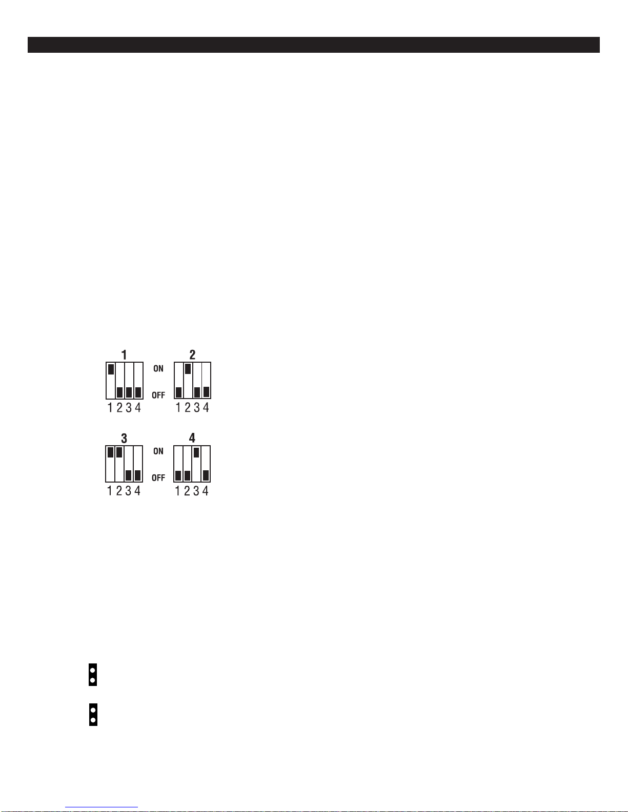
SSD, LCD, and VFD Control
Stations
These Control Stations have a four position DIP
switch on the circuit board to set the address and
supervision. To change the Control Station to unsupervised, move DIP switch 4 to the ON position. To
change the address, the DIP switch setting must be
positioned according to Figure 3.
LED Control Stations
These Control Stations have two jumpers on the circuit board to set the address and supervision. To
change the address of Control Station #1 to Control
Station #2, remove JP2 (see Figure 4). To change a
Control Station to unsupervised, remove JP1 (see
Figure 4).
Supervised and
Unsupervised Control
Stations
Figure 3 Control Station DIP Switch Settings
ICON Control Stations
These Control Stations have two jumpers on the circuit board to set the address and supervision. To
change the address of Control Station #3 to Control
Station #4, remove JP2 (see Figure 4). To change a
Control Station to unsupervised, remove JP1 (see
Figure 4).
Remove JP1 to unsupervise
JP1
Remove JP2 for keypad 2 (LED) or
keypad 4 (ICON)
JP2
A supervised Control Station is reported as missing
when the system fails to get any response from it.
If more than one supervised Control Station is set to
a particular address, then none of those Control Stations will function properly. Only one supervised
Control Station may be used at an address.
An unsupervised Control Station can be removed
from the system without the system detecting that it
is missing. The advantage of an unsupervised Control Station is that a system can have as many Control Stations as the power supply can support. Multiple unsupervised Control Stations may be used at
any address. When unsupervised SSD, LCD, and
VFD Control Stations are used, they must be set to
address 3 or 4. By adding additional power supplies,
like the HCP12SULC, Control Stations may be added
up to a total of 18 bus devices on the system.
For UL listed systems, unsupervised Control Stations are not allowed.
If an unsupervised Control Station is set to the same
address as a supervised Control Station, then the
unsupervised Control Station will not function. Do
not mix a supervised Control Station with unsupervised Control Stations at the same address.
Figure 4 LED & ICON Control Station Jumpers
9
CONTROL ST A TION TROUBLESHOOTING
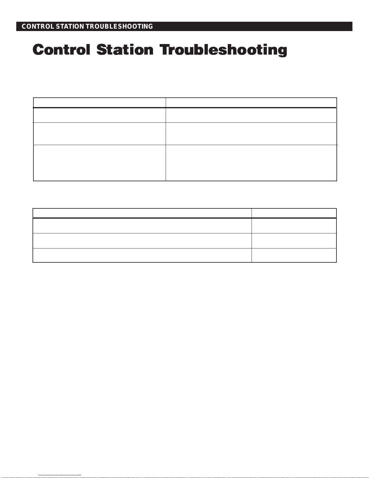
Control Station Troubleshooting
If a Control Station is incorrectly wired, it will not accept keystroke entries. The following symptoms may appear:
SYMPTOM CONDITION
No Control Station display or LEDs Black or Red Wire removed or cut
No response from key presses Green Wire removed or cut
Two supervised Control Stations at the same address
LEDs flash and may display White Wire removed or cut
“No Communication From Control” code Green/White Wires reversed
Green & White Wires shorted together
The nominal voltage at the control (with a single Control
Station connected) should measure as follows:
TERMINAL VOLTAGE
from Common Negative to GRN DATA ~ 9.3 VDC
from Common Negative to WHT DATA ~ 10.7 VDC
from Common Negative to KP+12V ~13.8 VDC
10
 Loading...