

Sentrol ZX200, ZX210 Installation And Programming Manual

SENTROL ZX200/ZX210
Security System Control
Installation/
Programming
1

2

Table of Contents
Feature Overview ..................................................................................................... 5
A New Standard For Value ........................................................................................5
ZX System Advantages..............................................................................................5
”More Than A Security System“ ................................................................................5
”Self-Watch“ Fire Zone Features................................................................................5
ZX200/ZX210 Wiring Diagram ................................................................................ 6
Control Board Terminal Descriptions ...................................................................... 7
“2 in 1” Zoning™ ..................................................................................................... 8
Conventional Methods of Wiring .......................................................................... 10
Class ‘B’ End-Of-Line Resistor Supervised Zones ......................................................10
Non-Supervised Closed Circuit Loop (No EOL Resistor Supervision) ........................ 10
TABLE OF CONTENTS
Wireless Devices ..................................................................................................... 11
Control Station Addressing and Supervision ........................................................ 12
SSD, LCD, and VFD Control Stations .......................................................................12
LED Control Stations ...............................................................................................12
Control Station Troubleshooting ........................................................................... 13
12 VDC Outputs ..................................................................................................... 14
Direct Connection to a PC for Remote Programming .......................................... 16
Operating the System ............................................................................................ 17
Powering Up With The Control Station ...................................................................17
Installer Arming and Disarming ............................................................................... 17
Installer On Premises ...............................................................................................17
Trouble Conditions .................................................................................................17
Clearing Trouble Messages ......................................................................................17
Testing ....................................................................................................................17
Programming the Control ..................................................................................... 18
Introduction ...........................................................................................................18
Local Programming .................................................................................................18
Remote Programming (RPM/2 Pro).........................................................................18
LED Control Station Programming ..........................................................................18
Programming Zone Names .....................................................................................19
3

TABLE OF CONTENTS
Installer Level Programming .................................................................................. 20
Menu Options.........................................................................................................20
Function Map ......................................................................................................... 24
Programming Notes ...............................................................................................40
Remote Connect ...........................................................................................20
Edit Function Map .........................................................................................20
Entering a New Value at a Location..................................................... 20
Programming the Account Code, Report Code, and Telephone Number Digits ..
Additional Programming Notes .......................................................... 21
Program User Codes......................................................................................21
Restore Factory Defaults ................................................................................21
Hours Until Next Comm Test.........................................................................22
Call RPM ....................................................................................................... 22
Program RF Data ...........................................................................................22
Programming RF Zone Devices Into the RF Gateway ............................22
Programming RF User Devices Into the RF Gateway .............................23
Programming RF Devices Into the Control Panel ..................................24
System Times ................................................................................................25
System Options .............................................................................................26
Keypad Options ............................................................................................ 27
Zone Definitions ............................................................................................ 28
User Authority Levels .....................................................................................29
Bell Output Activation ...................................................................................30
Programmable Outputs ................................................................................. 30
Programmable Output Activation.........................................................31
Communicator Options ................................................................................32
Event Reporting Phone Selection ................................................................... 33
Telephone Numbers ......................................................................................34
Dialed Digits Allowed ...........................................................................34
Account Numbers .........................................................................................34
Zone Report Code Digits ...............................................................................35
User Report Code Digits ................................................................................36
Auxiliary Key Alarm Report Code Digits .........................................................37
Other Trouble Report Code Digits .................................................................37
Other Event Report Code Digits ....................................................................39
21
Specifications And Features ................................................................................... 43
List of Compatible Accessories .............................................................................. 46
Digital Communicator Table For Contact ID Formats........................................... 47
Agency Requirements ............................................................................................ 49
National Fire Protection Association (NFPA) Rules ............................................... 51
FCC Compliance ..................................................................................................... 54
4

Feature Overview
FEATURE OVERVIEW
• 8 zones
• 2 or 4-wire fire zone capability
• Integrated Sentrol Series 4000
wireless
• Compatible with ESL 521 Smoke
Detector for automatic “Clean Me”
maintenance reporting
• Four exciting new keypads
• Pager reporting
A New Standard For Value
The ZX200/ZX210 Control System sets a new standard for value and end-user benefits. Highlights include 8 zone hardwire/wireless flexibility, unique
Lifestyle Enhancement features, and an easy to use
family of keypads. The ZX200/ZX210 control is preprogrammed at the factory with eight burglary zones
so it’s ready to power up and operate out of the
box. An optional output driver module provides 10
additional programmable outputs when desired.
ZX System Advantages
• Built-in telephone line monitor
• Supervised bell circuit
• Temporal rhythm fire bell coding
• Automatic Smoke Detector Reset
feature
• Fuse-Free
• 14" x 14" ‘Big Box’ enclosure available (model ZX210)
system at night can be as easy as saying…or pressing
“Night, Night”.
“More Than A Security System”
The ZX200/ZX210 does more than provide reliable
home security - it provides features that complement
family lifestyles. User On Premise lets you know
when someone’s arrived.
Pager Reporting notifies users of trouble, alarm conditions, or other reportable conditions on pagers with
digital displays.
The new ZX Control System offers significant benefits
for both the installer and end user. Commonality in
programming, operation, and accessories mean ZX
controls are easier to install and program and reduce
inventory and installation costs.
Compatible wireless receivers and sensors overcome
installation obstacles and increase sales and profit potential. Sensors have been engineered for long-range
stability and reliability and the modular 8-zone receiver,
with true diversity antenna, mounts anywhere for improved reception and performance.
Four all-new keypads provide unique features and displays for easy end-user operation. Each keypad features three distinct arming levels (Away, Stay & Night)
with backlit keys that show system status at a glance
and an easy to find Off key with automatic “Mute”
feature. Arming the system is easy with quick Two-
Button Arming or Double Press Arming. Arming the
“Self-Watch” Fire Zone Features
The ZX200/ZX210 ensures optimum fire zone performance and safety with unique “Self Watch” features. The ZX200/ZX210 is compatible with ESL’s
new 521 series smoke detectors for “Clean Me” Au-
tomatic Self-Diagnostic Reporting. This feature enables the panel to sense when the smoke detector
needs cleaning or maintenance over the same two
wires used for power and alarm signaling. The control will then signal the Central Station that a smoke
detector maintenance trouble signal has occurred letting you know
For added security, the ZX200/ZX210 incorporates
Automatic Smoke Detector Reset which automatically resets the smoke detectors following a manual
disarm of the fire system. The ZX200/ZX210 also
complies with new NFPA requirements for residential fire installations by providing Temporal Rhythm
Fire Coding and a Supervised Bell Circuit.
5
before a problem occurs.
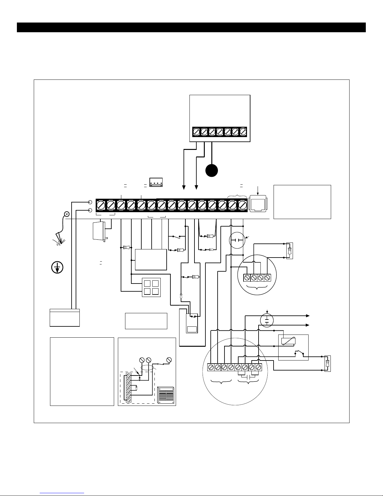
WIRING DIAGRAM
ZX200/ZX210 Wiring Diagram
+12V NEG
KEYPAD
EARTH
GROUND
UNIFIED
EARTH
GROUND
BATT
XFMR
TRANSFORMER
Recommended:
Basler BE 116220
16.5V / 20VA MIN.
U.L. CLASS II 50/60Hz
WARNING
Internally Fused.
Do Not Short.
Do Not Connect
To A Switched
Red and Black Leads RED = POS. (+) BLACK = NEG. (-)
Receptacle.
12V SEALED
LEAD ACID BATTERY
Yuasa B-1270
QUIESCENT CHARGE CURRENT: 20mA.
Replace: Every 3 - 5 years.
OWNERS INSTRUCTION
THIS EQUIPMENT SHOULD BE INSTALLED
IN ACCORDANCE WITH THE NATIONAL
FIRE PROTECTION ASSOCIATION’S
STANDARD 72 (NATIONAL FIRE
PROTECTION ASSOCIATION,
BATTERYMARCH PARK, QUINCY, MA
02269). PRINTED INFORMATION
DESCRIBING PROPER INSTALLATION,
OPERATION, TESTING, MAINTENANCE,
EVACUATION PLANNING AND REPAIR
SERVICE IS TO BE PROVIDED WITH THIS
EQUIPMENT.
FLOAT BATTERY
VOLTAGE:
13.6 - 13.8V
Max. current: 500mA.
NOTICE -
Class II
PowerLimited
AC
BELL
NEG
1500Ω
1/2 WATT
UL LISTED RESISTORS
MODEL CR853 - 825Ω E.O.L.
MODEL CR854 - 1500Ω E.O.L.
CONNECTION OF UL COMMERCIAL
POLARIZATION AND
NOISE SUPPRESSION
DIODE
JUMPER
Class II
PowerLimited
KP
+12V
BLACK
CONTROL STATIONS
AND OTHER
PERIPHERALS
UL LISTED
SIGNALING DEVICE
Ademco AB12M
BURGLAR AUDIBLE
-
+
1500Ω (CR854)
(EOL DEVICE)
GREEN WHITE
DATA
RED
BELLNEG
J-4
WHITE
GREEN
ZONE
2/6
ALL WIRING
BETWEEN CONTROL
& BELL MUST BE IN
CONDUIT.
ADEMCO AB12M
GRADE A BELL
COMMERCIAL
TO +12V AUX TERMINAL
ZONE
1/5
NEG
N.O.
N.C. ZONE 1
1500Ω
1/2 WATT
ZONE
METHOD 1
N.C.
1/2 WATT
ZONE 6
825Ω
1/4 WATT
MOTION
DETECTOR
TO NEG TERMINAL
ZONE
2/6
3/7
METHOD 2
N.C.
N.C.
ZONE 2
1500Ω
N.C.
TG+
PG01
NEG
ZONE 3
1500Ω
1/2 WATT
ZONE 7
825Ω
1/4 WATT
+
MPI-206
TG - COM NC NO
PROGRAMMABLE
OUTPUT 1
CONNECTION
Class II
PowerLimited
ZONE
2WS
4/8
SWNEG
+--
POWER
CONNECT
RJ31/33/45
CORD
+12V
TELCO
AUX
JACK
LISTED RATE OF RISE OR
FIXED TEMPERATURE THERMOSTAT
--
+
+
POWER
LISTED RATE OF RISE OR
FIXED TEMPERATURE THERMOSTAT
RED
BLACK
BROWN
ALARM
CONTACTS
SENTROL 4-WIRE MODELS
Telephone connection of the fire
alarm signal from this system to a
fire alarm headquarters or central
station is permitted only with the
approval of the authority having
jurisdiction.
1500Ω (CR854)
(EOL DEVICE)
SMOKE DETECTOR
SENTROL 2-WIRE MODELS
(See ZX200/ZX210
Interconnect Label
P/N 64600285-NOTE 2)
TO ANY ZONE DEFINED
AS 24-HOUR FIRE
BROWN
POWER SUPERVISION UNIT
ESL MODEL 204-12/24V OR EQUIV.
1500Ω (CR854)
SMOKE DETECTOR
(See ZX200/ZX210
Interconnect Label
P/N 64600285-NOTE 2)
(CONV ZONING)
FIGURE 1 Suggested UL Household Burglar Alarm and/or Fire (ƒƒ) Alarm Hookup
6

Control Board Terminal Descriptions
TERMINAL FUNCTION DESCRIPTION
AC
XFMR
BELL
AC Input
Supervised Bell Output
(power-limited)
Connect a 16.5 VAC 35 VA UL Class II transformer minimum using 18 gauge
minimum 2 conductor wire.Do not exceed 50 feet.
(+)12 VDC. Combined alarm current should not exceed 1.5 amps.
Overcurrent protected at 1.85 amps (PTC2). A 1500 Ohm EOL resistor
(CR854)
bell output fault will occur.
must be connected between the Bell and Neg terminals; otherwise a
TERMINAL DESCRIPTIONS
NEG
KP
+12V
GREEN
DATA
WHITE
DATA
ZONE 1/5
NEG
ZONE 2/6
ZONE 3/7
NEG
ZONE 4/8
2WS
SWNEG
+12V
AUX
Common Negative
Keypad Power
(power-limited)
Local Data Bus In
Local Data Bus Out
Zone 1/5 Loop (+)
Common Negative
Zone 2/6 Loop (+)
Zone 3/7 Loop (+)
Common Negative
Zone 4/8 Loop (+)
Two-Wire/Four-Wire Smoke
Switched Negative
Auxiliary Power
(power-limited)
BLACK WIRE - (-)12 VDC. Negative connection for Control Stations, ODM,
RF receiver, motion detectors, bell output, and other devices.
RED WIRE - (+)12 VDC 500 mA continuous power connection for Control
Stations, ODM, and RF Gateway. Overcurrent protected at 1.85 amps
(PTC1). CAUTION: Use the KP+12V and the +12V AUX terminals when
calculating total current drain.
GREEN WIRE - Connection for Control Stations, ODM and RF receiver. Use 22
gauge wire up to 1000 ft. Use 18 gauge wire up to 2000 ft.
WHITE WIRE - Connection for Control Stations, ODM and RF receiver. Use 22
gauge wire up to 1000 ft. Use 18 gauge wire up to 2000 ft.
Each loop requires a 1500 Ohm end-of-line resistor (P/N CR854) for the
primary zone and an 825 Ohm end-of-line resistor (P/N CR853) for the
secondary zone. A common negative is shared among all zones. The need for
end-of-line resistors may be eliminated on all Burglar defined zones through
programming. See Figure 2 and 3 for “2 in 1” Zoning™ wiring examples.
(-) Current limited 60 mA terminal. Negative connection for two-wire/fourwire smoke detectors, glass break detectors, and devices requiring resettable
power. The maximum series loop resistance for a two-wire smoke loop is 20
ohms. The maximum Alarm Impedance is 500 ohms.
(+)12 VDC 500 mA continuous power. Overcurrent protected at 1.85
amps (PTC1). Used for powering motion detectors, two-wire/four-wire smoke
detectors, glass break detectors, and other accessories. CAUTION: Use the
KP+12V and the +12V AUX terminals when calculating total current drain.
7
“2 in 1” Zoning™
“2 in 1” Zoning
™
NOTE
If a Normally Open Device (i.e., 4wire smoke detector) is used with
“2 in 1” Zoning™, a short will occur across both zone loops when
that device goes into alarm. It is
recommended that these types of
devices be used with Conventional
Zone wiring only.
The ZX200/ZX210 Security Control uses the “2 in
1” Zoning™ method that allows the installer to wire
two separate zones in parallel into one set of terminals that will save both time and wire costs.
Each zone is uniquely identified by its end-of-line
resistor. The Primary Zone (zones 1-4) in each terminal is identified by a 1500 Ohm EOL resistor. The
Secondary Zone (zones 5 - 8) is identified by an 825
Ohm EOL resistor. The Primary and Secondary zones
operate as two independent zones to provide separate reporting, programming, and displays. Each
zone is fully programmable (See Installer Level Programming). The zones are for Form A, Form B, or
Form C sensors. Maximum total loop wire and con-
tact resistance (not including EOL) must not exceed 100 Ohms for the loop to function properly.
There are two methods of wiring for “2 in 1” Zoning™. Method 1 wires one zone loop back to the
control while a second zone loop is added in parallel off the first. This method may be employed in
system retrofits, system expansions, or just simply
to save wire cost and labor.
Method 2 wires two separate zone loops back into
one set of terminals. The panel recognizes each loop
independently because two different EOL resistor
values are used to differentiate between the Primary
Zone (1500 Ohm 1/2 Watt) and the Secondary Zone
(825 Ohm 1/4 Watt). This method provides two
zones with one set of terminals and is ideal for prewire or already installed wiring.
1500Ω 1/2W
Primary Zone
Secondary Zone
825Ω 1/4W
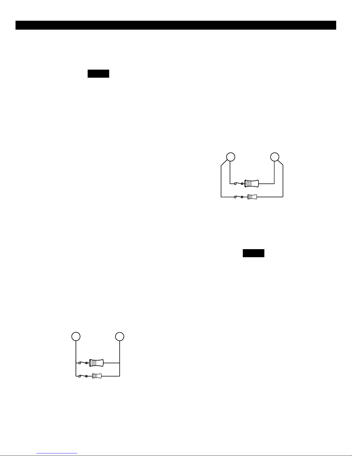
Figure 3 “2 in 1” Zoning™ Wiring - Method 2
NOTE
The resistors in Figures 2 & 3 are
1% values to maintain proper loop
resistance values. If replacements
are required, please refer to the
manufacturer for correct replacements. The 1500 Ohm resistor is
color coded Brown•Green•
Black•Brown•Brown. The 825
Ohm resistor is color coded
Gray•Red•Green•Black•Brown.
1500Ω 1/2W
Primary Zone
Secondary Zone
825Ω 1/4W
Figure 2 “2 in 1” Zoning™ Wiring - Method 1
All zones sense five different voltage levels enabling
one zone to act as two. Troubleshooting is simple
using just a voltmeter at the control. The control
monitors the voltage level across the zone and uses
the voltage levels in Table 1 to determine whether
the zone is normal, open, or shorted.
8
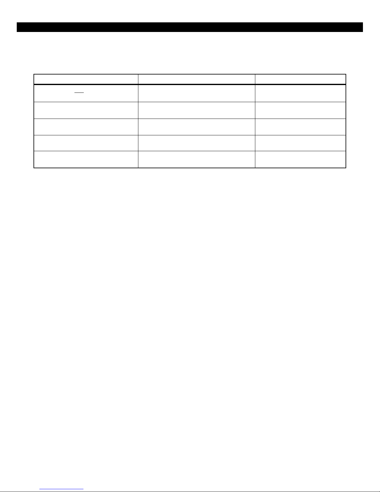
“2 in 1” Zoning™
CONDITION NOMINAL LOOP RESISTANCE VOLTAGE READING
Primary Zone and Secondary Zone Infinite Ohms 5.24 - 8.25 V
Open Contacts; Loop Cut or Open
Secondary Zone Open Contact, 1500 Ohms 4.24 - 5.23 V
Primary Zone Normal
Primary Zone Open Contact, 825 Ohms 3.24 - 4.23 V
Secondary Zone Normal
Primary Zone and Secondary Zone 825 Ohms in parallel with 2.00 - 3.23 V
Normal 1500 Ohms = 532 Ohms
Primary Zone and Secondary Zone 0 Ohms 0 - 1.99 V
Shorted
Table 1 “2 in 1” Zoning™ Troubleshooting Chart
9
CONVENTIONAL WIRING
Conventional Methods of Wiring
Class ‘B’ End-Of-Line Resistor
Supervised Zones
A Class ‘B’ zone must be supervised with a 1500
Ohm 1/2 Watt end-of-line resistor (P/N CR854). This
resistor should be installed in series at the furthest
point from the control. This configuration must be
used whenever both Form A and Form B devices are
connected and provides a high degree of protection against compromise or tampering. The control
monitors the voltage level across the Primary zone
and uses the Primary zone voltage levels in Table 1
to determine whether the zone is normal, open, or
shorted. The operation of a zone is programmable
(see Installer Level Programming). Maximum total
loop wire and contact resistance (not including
EOLs) must not exceed 100 Ohms for the loop to
function properly. The 1500 Ohm EOL resistor is
optional for Form A connections but is required
for Form B.
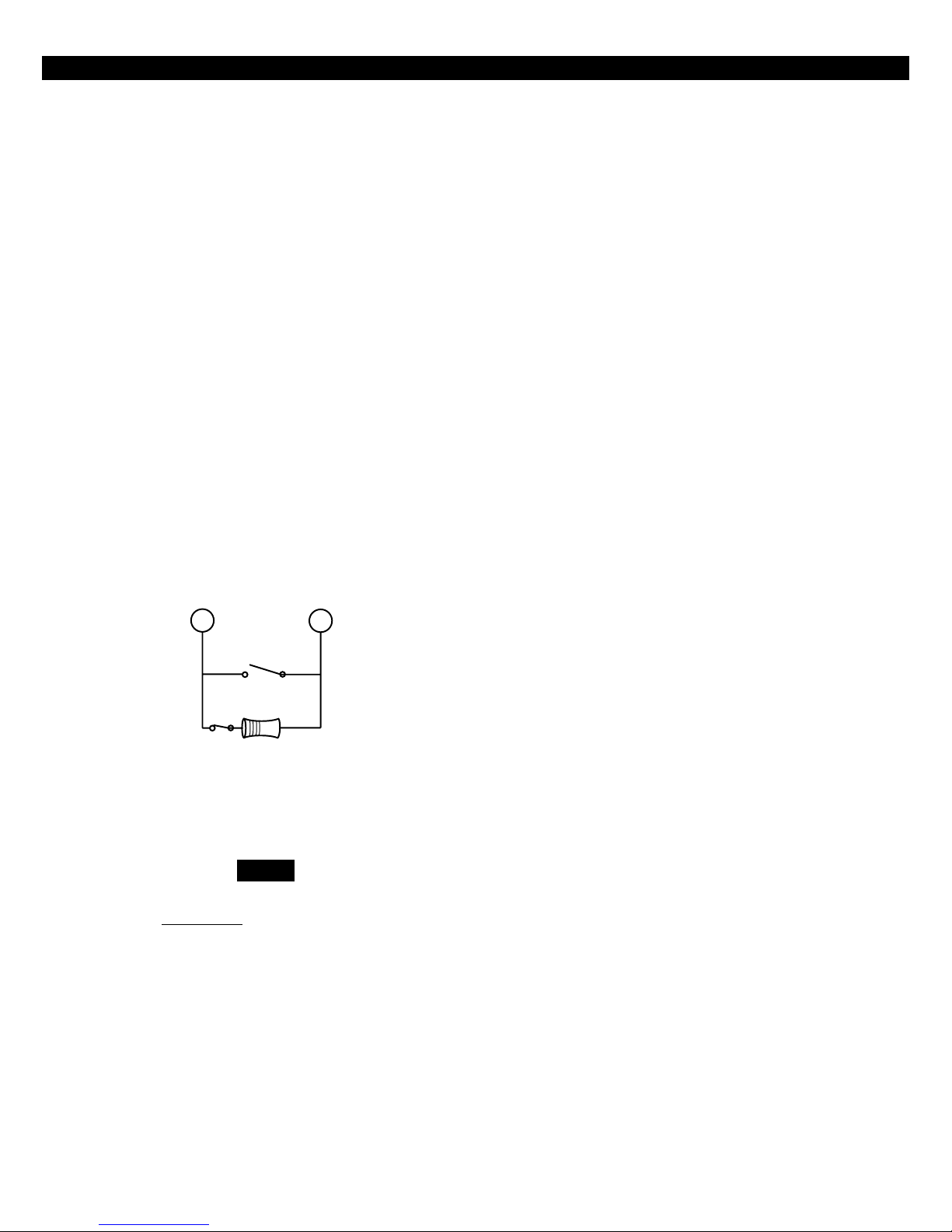
Normally
Open
Non-Supervised Closed Circuit Loop
(No EOL Resistor Supervision)
The EOL resistor is not required on Burglar zones. A
conventional closed circuit loop may be connected
directly to a primary zone and the zone will have
either a short or an open condition. See Installer Level
Programming for programming an unsupervised
zone. Fire zones may not be installed as unsupervised. Only Burglar defined zones may be wired
non-supervised. “2 in 1” Zoning™ is not allowed.
NOTEONLY BURGLAR DEFINED ZONES MAY
BE WIRED NON-SUPERVISED. “2 IN 1” ZON-
ING™ IS NOT ALLOWED.
1500Ω 1/2W
Primary Zone
Normally
Closed
Figure 4 Conventional Zone Wiring Method
NOTE
For UL Listed systems, EOL Supervi-
is required.
sion
10

Wireless Devices
WIRELESS DEVICES
The ZX200/ZX210 provides an option for including
Wireless (or RF) Devices. The RF Devices may consist
of RF Zone Devices (Universals, Door Contacts,
Glassbreaks, PIRs and Smoke Detectors) and RF User
Devices (Handhelds). These RF Devices require that
an RF Gateway be attached to the system. The
ZX200/ZX210 is compatible with either a model
4710 or 4720 RF Gateway. If a 4720 RF Gateway is
used, it must be set to address ‘1’. Refer to the RF
Gateway instructions for address selection.
Mount the RF Gateway as described in the RF Gateway instructions. Wire the local data bus to the terminals: +12V - RED; DATA A - GREEN; DATA B WHITE; NEG - BLACK. Set Address switch. Reinstall
the cover.
Each of the eight zones on the ZX200/ZX210 may
be programmed to be wireless (see Installer Level
Programming - Zone Definitions). If a zone is programmed to be wireless, then its hardwire connection is ignored and the zone’s status is retrieved from
the RF Gateway.
Up to eight RF Zone Devices and six RF User Devices
may be used (see Installer Level Programming - Programming RF Data Into the RF Gateway). An RF Zone
must be mapped to a zone by programming. An RF
User Device must be mapped to a valid user passcode
by programming.
The RF Gateway and RF Zone Devices should be temporarily mounted in their desired locations until they
have been tested with the Control Panel. These devices may need to be re-oriented or moved to achieve
optimal reception. After testing has been completed,
they should be permanently mounted.
Strong Signal (HOT or 5 Control Station beeps):
a strong or high level RF signal was measured by the
receiver for that location of the transmitter. This is a
good location for the transmitter and receiver.
Acceptable (ACC or 3 Control Station beeps): a
normal or acceptable level of RF signal was measured by the receiver for that location of the transmitter. This is a good location for the transmitter
and receiver.
Low Signal (LO or 1 Control Station beep): a low
or
not acceptable level of RF signal was measured
by the receiver for that location of the transmitter.
Make multiple test transmissions, making sure that
obstructions between the transmitter and receiver
are normal but minimized (hands away from units,
metal ladders away from receiver, etc.) during these
tests. The transmitter and/or receiver will need to
be relocated to obtain ACCEPTABLE level readings.
No Signal (NO or 1 long Control Station beep):
no RF signal or an extremely low RF signal was measured by the receiver for that location of the transmitter. Bring the transmitter to the RF Gateway and
activate the transmitter. The red LED on the RF Gateway should blink. If it does not, then the transmitter
is not working. If the red LED does blink, but the
signal strength is still NO SIGNAL, then a programming error exists. Check the programming of the
zone in both the RF Gateway and the panel. If the
signal strength is STRONG or ACCEPTABLE, then the
transmitter and/or receiver will need to be relocated
to obtain ACCEPTABLE level readings. Be sure to
power down the control to clear out all signal
strength levels before testing the transmitter at its
new location.
After testing has been completed, the RF Gateway and
RF Zone Devices should be permanently mounted.
To test the Received Signal Strength of each RF Zone
Device, use Test 6 - RF Signal Strength Test. From
the Control Station press the “8” key, followed by
the Installer Code (9632) and then press the “6”
key. Next press the RF Zone Device Number (1 to
8). The Control Station will display and sound the
Received Signal Strength of the last transmission sent
by the RF Zone Device.
NOTE
Series 4000 RF Gateways and transmitters which are not UL labeled are not
allowed in UL Certificated installations.
11

CONTROL STATION ADDRESSING AND SUPERVISION
Control Station Addressing and Supervision
All Control Stations are shipped from the factory as
Control Station #1 and supervised. They may be set
to other addresses and to unsupervised as described
below.
A supervised Control Station is reported as missing
when the system fails to get any response from it.
In order to maintain supervision, each supervised
Control Station must have its own unique address.
An unsupervised Control Station can be removed
from the system without the system detecting that
it is missing. The advantage of an unsupervised Control Station is that a system can have as many Control Stations as the power supply can support. By
adding additional power supplies, like the HCP12SUL, Control Stations may be added up to a total
of 18 bus devices on the system. For UL listed systems, unsupervised Control Stations are
not allowed.
SSD, LCD, and VFD Control Stations
When unsupervised Control Stations
are used, ALL unsupervised LED Control Stations
or 2, ALL unsupervised SSD, LCD, and
VFD Control Stations must be addressed as 3 or 4. You cannot mix a
supervised keypad and an unsupervised keypad with the same address
setting.
NOTE
must be addressed as 1
LED Control Stations
These Control Stations have two jumpers on the circuit board to set the address and supervision. To
change the address of the Control Station #1 to
Control Station #2, remove JP2 (see Figure 6). To
change a Control Station to unsupervised, remove
JP1 (see Figure 6).
These Control Stations have a four position DIP
switch on the circuit board to set the address and
supervision. To change the Control Station to unsupervised, move DIP switch 4 to the ON position. To
change the address, the DIP switch setting must be
positioned according to Figure 5.
1
ON
OFF
1234
3
ON
OFF
1234
Figure 5 Control Station DIP Switch Settings
2
1234
4
1234
Remove JP1 to unsupervise
JP1
Remove JP2 for keypad 2
JP2
Figure 6 LED Control Station Jumpers
12

CONTROL STATION TROUBLESHOOTING
Control Station Troubleshooting
If a Control Station is incorrectly wired, it will not
accept keystroke entries. The following symptoms
may appear:
SYMPTOM CONDITION
No Control Station display Black or Red Wire removed or cut
No response from key presses Green Wire removed or cut
Displays “No Communication From Control” code White Wire removed or cut
Green/White Wires reversed
Green & White Wires shorted together
The nominal voltage at the control should measure
as follows:
TERMINAL VOLTAGE
from Common Negative to GRN DATA ~ 8.7 VDC
from Common Negative to WHT DATA ~ 3.5 VDC
from Common Negative to KP+12V ~13.8 VDC
13

12 VDC OUTPUTS
12 VDC Outputs
The control is supplied with one keypad power
output, one auxiliary power output, one bell output, and one programmable (PGO1) low current
output. (See Figure 1). The low current output on
the control can supply 10 mA @ 3VDC.
Additional outputs can be added with the ZXODM
Output Driver Module. The module receives its
data from the local data bus and provides ten additional programmable outputs. The ODM outputs
provide +12 VDC on activation and must be limited to 40 mA of current draw.
The ODM must be addressed as ODM1. The ODM
comes defaulted from the factory as ODM1. You
may use multiple ODMs provided that power restrictions are followed. Connect the ODM to the
control as shown in Figure 7. Use the twelve (12)
wire cable provided with the ODM for the outputs as shown.
Output conditions can be programmed as one of
many conditions. Refer to Installer Level Programming for programming information and restrictions.
J3 CONNECTIONS
OUTPUT
WIRE COLOR
1Tan
2Pink
3Gray
4 Violet
5 Yellow
6 Orange
7Blue
8 Dk Brown
9 Green
10 White
NEG Black
12V* Red
DATA BUS CONNECTION
RED Connect to Control KP+12V
GREEN Connect to Control GREEN
WHITE Connect to Control WHITE
BLACK Connect to Control NEG
R19
C7
R21
C3
+
D9D7D6
R18
C5
R25
R29
HICKORY, NC
ASSEMBLED
IN USA
R22
R23
R28
60821484 REV A
COPYRIGHT 1996
D4
C11
D5
D10
R12
R15
R20
R16
D2C6D1
V3
V2
R27
Q2
ACTIVE
C10
D3
Q1
R14
R13
U2
C4
+
V1
J2
B NEG
A
12V
R24
R26
J1
U1
R2
1234
SENTROL
CONTROLS GROUP
Y1
C8
R17
PC BOARD
MADE IN (USA)
R3R4R5R6R7
OUTPUTS
5678
C2
C9
C1
R1
D8
+
U4
R9
R8
R11
R10
J3
NEG
910
12V
14
Data bus connection
Figure 7 ZXODM Wiring Diagram
NOTE
The outputs on this module have limited transient immunity and should
not leave the enclosure. Mount module via the double-sided tape provided
on the back of the ODM to the inside
of the control enclosure.
J3 Connector

12 VDC OUTPUTS
Outputs may be wired to indicator devices or relay
module triggers (like the MPI-206) provided the 40
mA current draw condition is not exceeded. Figure
8 shows a wiring example for a relay to ODM 1
Output 2. Figure 9 shows a wiring example of ODM
1 Output 1 to trigger an LED.
MPI-206
+12V NEG
Red Wire
TG+
Black Wire
TG - COM NC NO
Pink Wire
Connects to J3 (part of 12-wire cable)
Neg
TAN WIRE
BLACK WIRE
* A 470-1000Ω resistor may be used
Output 1
Figure 9 Output Connected to an LED
NOTE
NOTE
The LED and current limiting resistor
shown in Figure 9 are not supplied.
*
Figure 8 Output Connected to a Relay
NOTE
Do not exceed 250 mA of total current through the Red (+12V) and
Black wires (Negative) of the twelve
wire cable. Add 18 gauge wire from
the appropriate control panel terminals for total current drains in excess
of 250 mA.
15

DIRECT CONNECTION TO A PC
Direct Connection to a PC for Remote
Programming
This system requires that a line voltage be provided
in order for the telephone interface to operate. This
is normally provided via the telephone lines. When
performing a direct connection between the system
and a modem on a PC, the line voltage must be
ZX200/ZX210
ZONE
ZONE
2/6
3/7
NEG
ZONE
4/8
Red
1 Watt
Resistor
2WS
SWNEG
100Ω
Green
provided from the control panel’s terminal strip.
Connect a cable as shown below. This cable may be
purchased (P/N ZXDCC01 - ZX200 PC Direct Connection Cable) from Sentrol.
+12V
TELCO
AUX
JACK
RJ11
Red
Green
RJ11
Telco In
MODEM
Figure 10 Direct Connection to a PC
16

Operating the System
OPERATING THE SYSTEM
Powering Up With The Control
Station
The control comes from the manufacturer with a
factory set (default) program. The factory default
code for user passcode No. 1 is “1234”. This
passcode is authorized to perform all user level functions. The default setting for the installer passcode
is “9632”. The installer passcode performs the installer level functions. For purposes of discussion, the
installer and the end user are both considered system users, but have different levels of authorization.
(See Installer Level Programming - User Authority
Levels).
When a Control Station is powered-up, it briefly displays a test pattern followed by its data bus address.
The Control Station will then begin displaying information from the control panel. During the first fifteen seconds after power-up, the control panel will
instruct the Control Station to display the panel’s
software revision and flash the AWAY, STAY, NIGHT,
READY, and TROUBLE LEDs.
Installer Arming and Disarming
The installer passcode may be used to arm the system. It may be used to disarm, but only if the system was armed by the installer passcode. It may be
used to silence alarms and to silence trouble conditions. When it is used to silence a Burglar alarm, it
will not disarm or cancel the alarm unless the system was armed by the installer passcode. For a detailed description of arming and disarming procedures, see the appropriate User Guide.
Installer On Premises
The first time that an Installer level passcode is used
to perform a function, an “Installer On Premises”
event is logged to be reported. Before leaving the
premises, press and hold the CLEAR key for three
seconds and an “Installer Off Premises” event will
be logged to be reported.
Trouble Conditions
The possible trouble conditions are:
AC Power Failure Fire Trouble
Low Battery Silenced Fire Alarm
Memory Error Zone Missing
Communication Failure RF Point Not Reporting
Missing Keypad Smoke Trouble
RF Jamming RF Point Tamper
Bell Fault RF Point Low Battery
Telco Line Fault RF User Device Low Battery
Zone Trouble
If RF Jamming is detected for at least 90 seconds, then
all RF Burglar zones will be faulted.
Clearing Trouble Messages
Most trouble conditions are cleared automatically
when the condition that initiated the trouble is restored or is eliminated. Three trouble conditions
(Memory Error, Smoke Trouble and Missing Keypad)
may be cleared manually by pressing and holding
the Clear key for three seconds (until two beeps are
heard). This action is also required to turn off the
Duress output after it has been activated and to cause
an “Installer Off Premises” event (see Operating the
System - Installer On Premises).
Testing
The ZX200/ZX210 provides the following testing capabilities: Walk Test, Battery Test, Bell Test, Communicator Test, Keypad Test and RF Signal Strength Test.
Refer to the appropriate User Guide for instructions
on performing these tests. Always ensure that a Walk
Test (and an RF Signal Strength Test when applicable)
is performed on a new installation.
17
 Loading...