

Sentrol ESL 2500,ESL 2500 Instruction Manual

1
a product of sentrol, inc
esl
ESL 2500
Keypad
Instruction Manual

2

3
TABLE OF CONTENTS
1.0 System Operation ....................................................................................... 4
1.1 The ESL 2500 Keypad ............................................................................... 4
1.2 The Keypad Keys ....................................................................................... 5
1.3 The Keypad Display ................................................................................... 5
1.4 Passcodes ................................................................................................... 6
2.0 Alarm Conditions ....................................................................................... 7
2.1 Identifying Zone Conditions ...................................................................... 7
2.2 Silencing Alarms ........................................................................................ 7
3.0 Trouble Conditions..................................................................................... 8
3.1 Identifying System Trouble Conditions ..................................................... 8
3.2 Silencing Trouble ....................................................................................... 9
4.0 Programming Menu Mode Options ........................................................... 10
4.1 Programming the System ........................................................................ 10
4.1.1 Programming the BMB.................................................................. 10
4.1.2 Defaulting the BMB ....................................................................... 12
4.1.3 Programming the DAC.................................................................. 13
4.1.4 Programming the Zone Names ..................................................... 14
4.1.5 Tech and User Codes .................................................................... 17
4.2 Connect ................................................................................................... 19
4.3 Event Log ................................................................................................. 19
4.3.1 View Log ....................................................................................... 20
4.3.2 Print Log ....................................................................................... 21
4.3.3 Clear Log ...................................................................................... 22
4.4 Comm Test .............................................................................................. 23
4.5 Lamp Test ................................................................................................ 23
4.6 Set Clock ................................................................................................. 24
5.0 Fire Detection .......................................................................................... 25
5.1 Introduction ............................................................................................ 25
5.2 When an Alarm Occurs ........................................................................... 25
5.3 Resetting the Fire Alarm System ............................................................. 25
5.4 Developing An Evacuation Plan ............................................................... 26
5.5 Fire-Safety Basics .................................................................................... 26
5.6 Know Fire Hazards .................................................................................. 27
5.7 In Case Of Fire ........................................................................................ 27
5.8 Be Prepared ............................................................................................. 27
5.9 Zone Trouble ........................................................................................... 28
Owner’s Insurance Premium Credit Requested ................................................ 29
4
1.0 SYSTEM OPERATION
Read these instructions carefully to familiarize yourself with the system. Your
system has been customized to meet your specific requirements. If you have
questions concerning the features on your system, consult your Fire Protection
Representative. Refer to the ESL 2501 Fire Alarm Control Panel Installation
Manual 64812711 for installation and configuration information before proceeding.
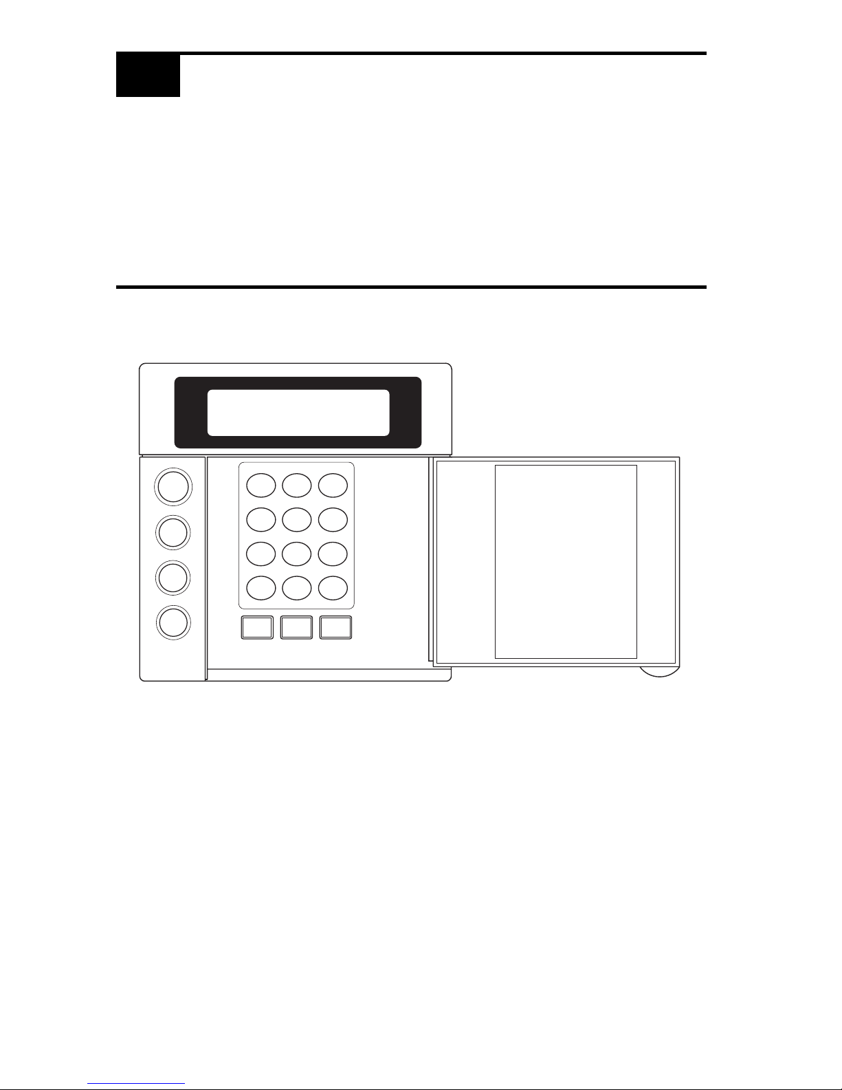
1.1 THE ESL 2500 KEYPAD
SYSTEM
RESET
ALARM
SILENCE
TROUBLE
SILENCE
1
23
4
56
7
89
CLEAR
0
ENTER
VIEW INFO ALM MEM
EVENT LOG
BYPASS DELAY ARM CHIME
RST SMOKE TEST PROGRAM
QUIT ACCESS INSTANT
HOME NEXT
D
MENU
NEXT
PREV

5
1.2 THE KEYPAD KEYS
MENU KEY
Used to enter the programming mode.
SYSTEM RESET KEY
Resets the system if the system is in alarm or trouble and forces a
battery test. The proper passcode must be entered.
ALARM SILENCE KEY
Silences alarms when the proper passcode is entered.
TROUBLE SILENCE KEY
Silences all system troubles when the proper passcode is entered.
PROGRAMMING KEYS
Used in the programming mode for menu and data entry scrolling and
passcode entry.
1.3 THE KEYPAD DISPLAY
TROUBLE
SILENCE
SYSTEM
RESET
ALARM
SILENCE
MENU
PREVNEXT
CLEAR
ENTER
NOTE: To save power, the keypad display will dim and go into screen saver mode
after four (4) minutes of no keypresses. Press any key to turn the display back ON.
SYSTEM NORMAL
JAN 21 05:27:52

6
1.4 PASSCODES
The ESL 2501 Fire Alarm Control Panel (FACP) uses two passcode levels, technician and user. Each passcode is four digits long. The user passcode allows resetting
and silencing the FACP and programming of a limited number of items. The
technician passcode also allows full programming of the FACP. Section 4.0
Programming Menu Mode Options details which items are accessible.
The default user passcode is: .
NOTE: This passcode may have been changed during installation.
0
0 0 0

7
2.0 ALARM CONDITIONS
2.1 IDENTIFYING ZONE CONDITIONS
If a zone causes an alarm, the system status is displayed on the first line. The
status of zones in alarm and trouble are displayed on the second line. The top line
scrolls all existing system conditions. The second line scrolls the status of all
existing system and zone conditions. Multiple system and zone conditions are
scrolled alternately on the second line of the display. For complete zone or system
status details, view the Event Log.
Position “a”: A if in Fire Alarm
S if Supervisory Alarm
Position “b”: T if in Trouble
W if in Walk-Test
M if in Maintenance
2.2 SILENCING ALARMS
1. Press . The Keypad displays:
2. Enter passcode: .
FIRE ALARM
ZONE# :ab
ALARM SILENCE
ENTER PASSCODE
ALARM
SILENCE

8
3.1 IDENTIFYING SYSTEM TROUBLE CONDITIONS
SYSTEM TROUBLE
XXX :T
3.0 TROUBLE CONDITIONS
When your system detects a trouble condition, the Keypad will alternate between
displaying System Trouble and any other existing system conditions. The specific
trouble messages are alternately displayed on the second line of the display, with
each message displayed for two seconds at a time.
Keypad System
Trouble Description
NO AC POWER
Indicates the loss of AC power or that the AC voltage is not high enough to power the
system.
LOW BATTERY Indicates that the battery voltage is low or the batteries are missing.
BELL Indicates that there is a short or open in the wiring or that the EOL is missing.
GROUND FAULT Indicates an earth ground connection to the system.
BELL SILENCE Indicates that a bell (NAC) has been silenced.
DRILL TEST Indicates that a drill test is being performed.
HIBERNATION Indicates that the panel has gone into hibernation mode.
LEM/LRM
Indicates a problem with the LEM/LRM module.
TELCO
Indicates a problem with a 2500-DACT phone line.
EXPANDER Indicates a missing ZEM module.
DAC Indicates a problem with the 1500-DAC2 module.
KEYPAD Indicates a missing supervised keypad.
RA Indicates a missing supervised RA.
COMM
Indicates a 2500-DACT communication failure.
MEMORY Indicates a function map memory failure. Enter programming mode to clear.

9
3.2 SILENCING TROUBLE
To silence the trouble sounder:
1. Press . The Keypad displays:
2. Enter passcode: .
After you silence the trouble sounder, the Keypad display will alternate between
the system status and the trouble message.
TROUBLE SILENCE
ENTER PASSCODE
TROUBLE
SILENCE

10
MAIN MENU
EXIT
1,2
PROGRAM
SYSTEM
1,2
CONNECT
2
EVENT
LOG
2
COMM
TEST
2
SET
CLOCK
2
Exit
1,2
Program
BMB
2
Program
DAC
2
Default
BMB
2
Default
DAC
2
Zone
Names
1,2
Tech Code
2
User Code
1,2
Exit
2
View Log
2
Print Log
2
Clear Log
2
MENU
MENU
ENTER PASSCODE
LAMP
TEST
2
1
User Passcode Required
2
Technician Passcode Required
4.0 PROGRAMMING MENU MODE OPTIONS
Your system has several features which you may be able to program yourself. DO
NOT attempt to program the system unless you have been trained on programming procedures and you fully understand these operations. The following menu
tree may be scrolled using the programming keys PREV, NEXT, ENTER and
CLEAR.
4.1 PROGRAMMING THE SYSTEM
4.1.1 PROGRAMMING THE BMB
1. Press . The Keypad displays:
2. Enter passcode: .
 Loading...