

Page 1

1
a product of sentrol, inc
esl
ESL 2500
Keypad
Instruction Manual
Page 2

2
Page 3

3
TABLE OF CONTENTS
1.0 System Operation ....................................................................................... 4
1.1 The ESL 2500 Keypad ............................................................................... 4
1.2 The Keypad Keys ....................................................................................... 5
1.3 The Keypad Display ................................................................................... 5
1.4 Passcodes ................................................................................................... 6
2.0 Alarm Conditions ....................................................................................... 7
2.1 Identifying Zone Conditions ...................................................................... 7
2.2 Silencing Alarms ........................................................................................ 7
3.0 Trouble Conditions..................................................................................... 8
3.1 Identifying System Trouble Conditions ..................................................... 8
3.2 Silencing Trouble ....................................................................................... 9
4.0 Programming Menu Mode Options ........................................................... 10
4.1 Programming the System ........................................................................ 10
4.1.1 Programming the BMB.................................................................. 10
4.1.2 Defaulting the BMB ....................................................................... 12
4.1.3 Programming the DAC.................................................................. 13
4.1.4 Programming the Zone Names ..................................................... 14
4.1.5 Tech and User Codes .................................................................... 17
4.2 Connect ................................................................................................... 19
4.3 Event Log ................................................................................................. 19
4.3.1 View Log ....................................................................................... 20
4.3.2 Print Log ....................................................................................... 21
4.3.3 Clear Log ...................................................................................... 22
4.4 Comm Test .............................................................................................. 23
4.5 Lamp Test ................................................................................................ 23
4.6 Set Clock ................................................................................................. 24
5.0 Fire Detection .......................................................................................... 25
5.1 Introduction ............................................................................................ 25
5.2 When an Alarm Occurs ........................................................................... 25
5.3 Resetting the Fire Alarm System ............................................................. 25
5.4 Developing An Evacuation Plan ............................................................... 26
5.5 Fire-Safety Basics .................................................................................... 26
5.6 Know Fire Hazards .................................................................................. 27
5.7 In Case Of Fire ........................................................................................ 27
5.8 Be Prepared ............................................................................................. 27
5.9 Zone Trouble ........................................................................................... 28
Owner’s Insurance Premium Credit Requested ................................................ 29
Page 4
4
1.0 SYSTEM OPERATION
Read these instructions carefully to familiarize yourself with the system. Your
system has been customized to meet your specific requirements. If you have
questions concerning the features on your system, consult your Fire Protection
Representative. Refer to the ESL 2501 Fire Alarm Control Panel Installation
Manual 64812711 for installation and configuration information before proceeding.
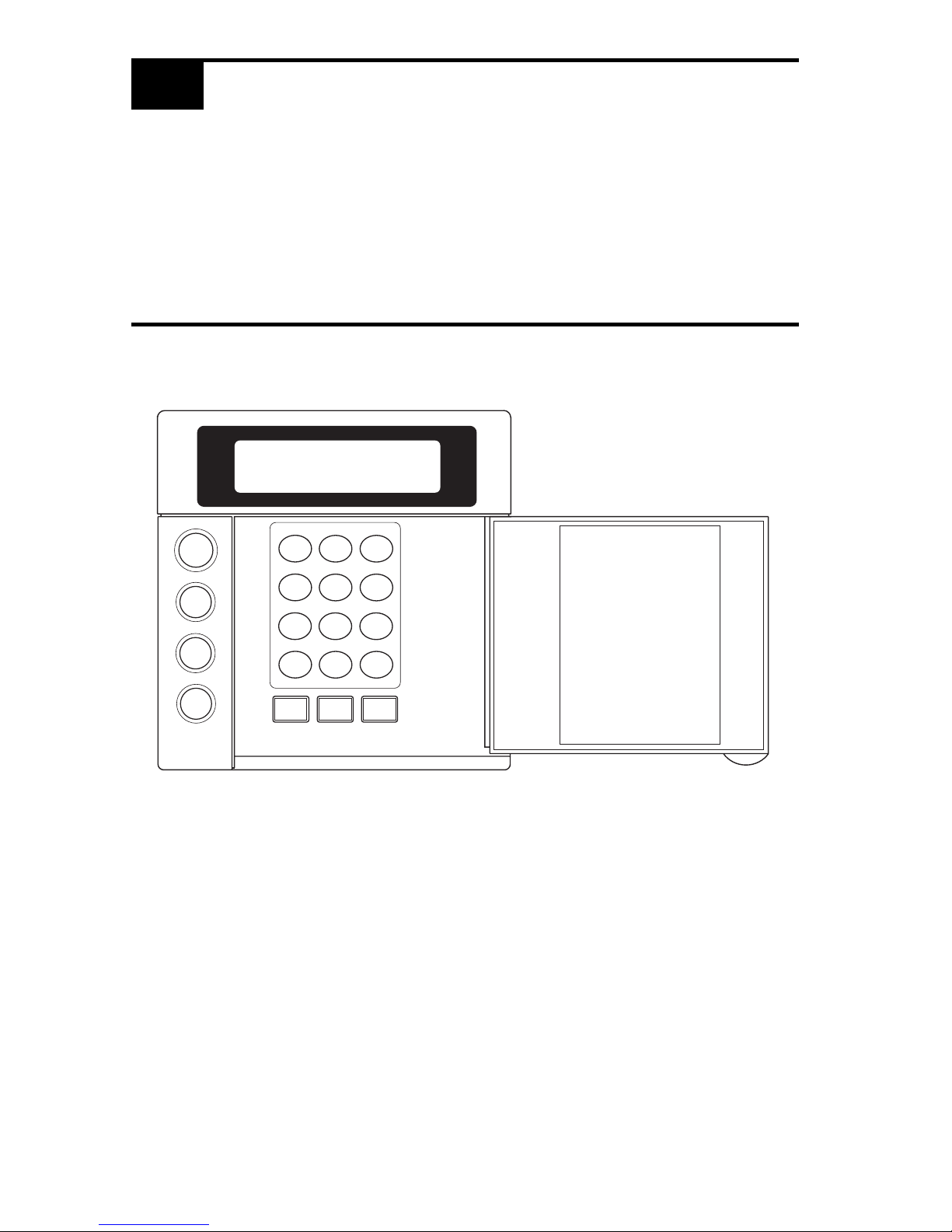
1.1 THE ESL 2500 KEYPAD
SYSTEM
RESET
ALARM
SILENCE
TROUBLE
SILENCE
1
23
4
56
7
89
CLEAR
0
ENTER
VIEW INFO ALM MEM
EVENT LOG
BYPASS DELAY ARM CHIME
RST SMOKE TEST PROGRAM
QUIT ACCESS INSTANT
HOME NEXT
D
MENU
NEXT
PREV
Page 5

5
1.2 THE KEYPAD KEYS
MENU KEY
Used to enter the programming mode.
SYSTEM RESET KEY
Resets the system if the system is in alarm or trouble and forces a
battery test. The proper passcode must be entered.
ALARM SILENCE KEY
Silences alarms when the proper passcode is entered.
TROUBLE SILENCE KEY
Silences all system troubles when the proper passcode is entered.
PROGRAMMING KEYS
Used in the programming mode for menu and data entry scrolling and
passcode entry.
1.3 THE KEYPAD DISPLAY
TROUBLE
SILENCE
SYSTEM
RESET
ALARM
SILENCE
MENU
PREVNEXT
CLEAR
ENTER
NOTE: To save power, the keypad display will dim and go into screen saver mode
after four (4) minutes of no keypresses. Press any key to turn the display back ON.
SYSTEM NORMAL
JAN 21 05:27:52
Page 6

6
1.4 PASSCODES
The ESL 2501 Fire Alarm Control Panel (FACP) uses two passcode levels, technician and user. Each passcode is four digits long. The user passcode allows resetting
and silencing the FACP and programming of a limited number of items. The
technician passcode also allows full programming of the FACP. Section 4.0
Programming Menu Mode Options details which items are accessible.
The default user passcode is: .
NOTE: This passcode may have been changed during installation.
0
0 0 0
Page 7

7
2.0 ALARM CONDITIONS
2.1 IDENTIFYING ZONE CONDITIONS
If a zone causes an alarm, the system status is displayed on the first line. The
status of zones in alarm and trouble are displayed on the second line. The top line
scrolls all existing system conditions. The second line scrolls the status of all
existing system and zone conditions. Multiple system and zone conditions are
scrolled alternately on the second line of the display. For complete zone or system
status details, view the Event Log.
Position “a”: A if in Fire Alarm
S if Supervisory Alarm
Position “b”: T if in Trouble
W if in Walk-Test
M if in Maintenance
2.2 SILENCING ALARMS
1. Press . The Keypad displays:
2. Enter passcode: .
FIRE ALARM
ZONE# :ab
ALARM SILENCE
ENTER PASSCODE
ALARM
SILENCE
Page 8

8
3.1 IDENTIFYING SYSTEM TROUBLE CONDITIONS
SYSTEM TROUBLE
XXX :T
3.0 TROUBLE CONDITIONS
When your system detects a trouble condition, the Keypad will alternate between
displaying System Trouble and any other existing system conditions. The specific
trouble messages are alternately displayed on the second line of the display, with
each message displayed for two seconds at a time.
Keypad System
Trouble Description
NO AC POWER
Indicates the loss of AC power or that the AC voltage is not high enough to power the
system.
LOW BATTERY Indicates that the battery voltage is low or the batteries are missing.
BELL Indicates that there is a short or open in the wiring or that the EOL is missing.
GROUND FAULT Indicates an earth ground connection to the system.
BELL SILENCE Indicates that a bell (NAC) has been silenced.
DRILL TEST Indicates that a drill test is being performed.
HIBERNATION Indicates that the panel has gone into hibernation mode.
LEM/LRM
Indicates a problem with the LEM/LRM module.
TELCO
Indicates a problem with a 2500-DACT phone line.
EXPANDER Indicates a missing ZEM module.
DAC Indicates a problem with the 1500-DAC2 module.
KEYPAD Indicates a missing supervised keypad.
RA Indicates a missing supervised RA.
COMM
Indicates a 2500-DACT communication failure.
MEMORY Indicates a function map memory failure. Enter programming mode to clear.
Page 9

9
3.2 SILENCING TROUBLE
To silence the trouble sounder:
1. Press . The Keypad displays:
2. Enter passcode: .
After you silence the trouble sounder, the Keypad display will alternate between
the system status and the trouble message.
TROUBLE SILENCE
ENTER PASSCODE
TROUBLE
SILENCE
Page 10

10
MAIN MENU
EXIT
1,2
PROGRAM
SYSTEM
1,2
CONNECT
2
EVENT
LOG
2
COMM
TEST
2
SET
CLOCK
2
Exit
1,2
Program
BMB
2
Program
DAC
2
Default
BMB
2
Default
DAC
2
Zone
Names
1,2
Tech Code
2
User Code
1,2
Exit
2
View Log
2
Print Log
2
Clear Log
2
MENU
MENU
ENTER PASSCODE
LAMP
TEST
2
1
User Passcode Required
2
Technician Passcode Required
4.0 PROGRAMMING MENU MODE OPTIONS
Your system has several features which you may be able to program yourself. DO
NOT attempt to program the system unless you have been trained on programming procedures and you fully understand these operations. The following menu
tree may be scrolled using the programming keys PREV, NEXT, ENTER and
CLEAR.
4.1 PROGRAMMING THE SYSTEM
4.1.1 PROGRAMMING THE BMB
1. Press . The Keypad displays:
2. Enter passcode: .
Page 11

11
The Keypad displays:
3. Press . The Keypad displays:
4. Press . The Keypad displays:
5. Press until the Keypad displays:
6. Press . The Keypad displays:
See Section 5.6 Programming Matrix of the ESL 2501 Fire Alarm Control Panel
Installation Manual for locations and values.
7. Use the , and numeric keys to enter the desired location.
Press and the cursor moves to the value field. Use the ,
and numeric keys to change the value for the selected location.
Press to accept the new value and advance to the next location.
Use to move the cursor back to location to select a different location.
MAIN MENU
EXIT
NEXT
ENTER
MAIN MENU
PROGRAM SYSTEM
PROGRAM SYSTEM
EXIT
NEXT
PROGRAM SYSTEM
PROGRAM BMB
ENTER
PROGRAM BMB
LOC:001 VAL:001
PREVNEXT
CLEAR
ENTER
PREV
NEXT
ENTER
Page 12

12
4.1.2 DEFAULTING THE BMB
1. Press . The Keypad displays:
2. Enter passcode: .
The Keypad displays:
3. Press . The Keypad displays:
4. Press . The Keypad displays:
5. Press until the Keypad displays:
6. Press . The Keypad displays:
7. Press to complete operation.
See Section 5.6 Programming Matrix of the ESL 2501 Fire Alarm Control Panel
Installation Manual for Location and Value settings for the Function Map defaults.
MENU
MENU
ENTER PASSCODE
MAIN MENU
EXIT
NEXT
ENTER
MAIN MENU
PROGRAM SYSTEM
PROGRAM SYSTEM
EXIT
NEXT
PROGRAM SYSTEM
DEFAULT BMB
ENTER
DEFAULT BMB
ENTER = COMPLETE
ENTER
Page 13

13
4.1.3 PROGRAMMING THE DAC
The ESL 1500-DAC2 Digital Alarm Communicator is programmed using the ESL
Model 1200-DPG programmer. Refer to the ESL 1500-DAC2 Installation Manual
P/N 64812689.
Page 14

14
4.1.4 PROGRAMMING THE ZONE NAMES
1. Press . The Keypad displays:
2. Enter passcode: .
The Keypad displays:
3. Press . The Keypad displays:
4. Press . The Keypad displays:
5. Press until the Keypad displays:
6. Press . The Keypad displays:
MENU
ENTER PASSCODE
MAIN MENU
EXIT
NEXT
ENTER
MAIN MENU
PROGRAM SYSTEM
PROGRAM SYSTEM
EXIT
NEXT
PROGRAM SYSTEM
ZONE NAMES
MENU
ENTER
ZONE 01
ZONE 01
Page 15

15
7. The Keypad will display the zone number selected on the first line and the
zone name to be programmed on the second line.
Press or to change the zone number.
Press to edit the displayed zone’s name.
8. Press the key associated with each character listed on the next page to enter
in the new zone name. Each keypress will change the display to the next
character listed for that key. A maximum of 10 letters (including spaces) may
be used for each zone name.
9. Press to start over if a mistake is made or press
to save the zone name and return to the zone number prompt.
10. Press from the zone number prompt to exit.
NEXT PREV
ENTER
ENTER
CLEAR
CLEAR
Page 16

16
0123456789:;<=>? @
AB C
DE F
GH I
JK L
MN O
PQ R S
TU V
WXYZ[¥]^_
space ! “ # $ % & ‘ * + , - . /
Used to move the cursor back one position
Used to move the cursor forward one position
KEY CHARACTER AVAILABLE
1
2
3
4
5
6
7
8
9
0
PREV
NEXT
Page 17

17
4.1.5 TECH AND USER CODES
1. Press . The Keypad displays:
2. Enter passcode: .
The Keypad displays:
3. Press . The Keypad displays:
4. Press . The Keypad displays:
5. Press until the Keypad displays:
6. Press . The Keypad displays:
Where XXXX is the current passcode
MENU
ENTER PASSCODE
MAIN MENU
EXIT
NEXT
ENTER
MAIN MENU
PROGRAM SYSTEM
PROGRAM SYSTEM
EXIT
NEXT
PROGRAM SYSTEM
TECH CODE
MENU
ENTER
XXXX
ENTER = COMPLETE
PROGRAM SYSTEM
USER CODE
or
Page 18

18
7. Set the new passcode (see example below)
Example: To set the passcode to 1234
Press
8. Press to exit or to save changes.
1
2
3 4
CLEAR ENTER
Page 19

19
4.2 CONNECT
This option is not available at this time.
4.3 EVENT LOG
1. Press . The Keypad displays:
2. Enter passcode: .
The Keypad displays:
3. Press until the Keypad displays:
4. Press . The Keypad displays:
MENU
MENU
ENTER PASSCODE
MAIN MENU
EXIT
NEXT
ENTER
MAIN MENU
EVENT LOG
EVENT LOG
EXIT
Page 20

20
4.3.1 VIEW LOG
1. Press . The Keypad displays:
2. Enter passcode: .
The Keypad displays:
3. Press until the Keypad displays:
4. Press . The Keypad displays:
5. Press . The Keypad displays:
6. Press . The Keypad display alternates between:
7. Event #1 is the last or newest event in the log, not the oldest.
8. Press or to scroll through all the events.
MENU
MENU
ENTER PASSCODE
MAIN MENU
EXIT
NEXT
ENTER
MAIN MENU
EVENT LOG
EVENT LOG
EXIT
NEXT
EVENT LOG
VIEW LOG
ENTER
EVENT#: 01
JAN 02 16:15
ZONE 01
FIRE ALARM
Event Number and Time/Date Stamp
Event Description
NEXT PREV
Page 21

21
4.3.2 PRINT LOG
1. Press . The Keypad displays:
2. Enter passcode: .
The Keypad displays:
3. Press until the Keypad displays:
4. Press . The Keypad displays:
5. Press . The Keypad displays:
6. Press . The Keypad displays:
7. Press . The Keypad displays:
MENU
MENU
ENTER PASSCODE
MAIN MENU
EXIT
NEXT
ENTER
MAIN MENU
EVENT LOG
EVENT LOG
EXIT
NEXT
EVENT LOG
PRINT LOG
ENTER
EVENT LOG
PRINT LOG
ENTER
PRINT LOG
ENTER = COMPLETE
Page 22

22
4.3.3 CLEAR LOG
1. Press . The Keypad displays:
2. Enter passcode: .
The Keypad displays:
3. Press until the Keypad displays:
4. Press . The Keypad displays:
5. Press . The Keypad displays:
6. Press . The Keypad displays:
7. Press . The Keypad displays:
MENU
MENU
ENTER PASSCODE
MAIN MENU
EXIT
NEXT
ENTER
MAIN MENU
EVENT LOG
EVENT LOG
EXIT
NEXT
EVENT LOG
CLEAR LOG
ENTER
CLEAR LOG
ENTER = COMPLETE
EVENT LOG
CLEAR LOG
ENTER
Page 23

23
1. Press . The Keypad displays:
2. Enter passcode: .
The Keypad displays:
3. Press until the Keypad displays:
4. Press . The Keypad displays:
5. Press .
The Keypad will turn on every dot on the display, all the lightable keys, and
the piezo for 5 seconds. The keypad will return to normal operation.
4.4 COMM TEST
This option is not available at this time.
4.5 LAMP TEST
MENU
MENU
ENTER PASSCODE
MAIN MENU
EXIT
NEXT
ENTER
MAIN MENU
LAMP TEST
LAMP TEST
ENTER = COMPLETE
ENTER
Page 24

24
4.6 SET CLOCK
1. Press . The Keypad displays:
2. Enter passcode: .
The Keypad displays:
3. Press until the Keypad displays:
4. Press . The Keypad displays:
5. Set the new time and date. (See example)
Example: To set the clock to 2:15 pm on June 17, 1997:
Press
Press
6. Press to start over if a mistake is made or press
to save changes.
MENU
MENU
ENTER PASSCODE
MAIN MENU
EXIT
NEXT
ENTER
MAIN MENU
SET CLOCK
10:53 02/04/1997
ENTER = COMPLETE
4
5
1
1
CLEAR
ENTER
6
1
7
90 9
7
1
(2:15 pm)
(June 17, 1997)
Page 25

25
5.0 FIRE DETECTION
5.1 INTRODUCTION
All fire systems require regular testing and maintenance. Common dust buildup in
smoke detectors can cause them to false alarm or fail in a time of need. Consult
your Security Company Representative for a scheduled maintenance program.
All devices in a Fire Alarm system should be tested monthly except as described in
NFPA 72.
5.2 WHEN AN ALARM OCCURS
When a fire alarm occurs, the bell sounds, the keypad(s) produces the fire alarm
tone and displays the message “FIRE ALARM” and the fire alarm system zone that
initiated the alarm.
DO NOT IMMEDIATELY ASSUME IT IS A “FALSE ALARM”!
The occupants should respond according to the fire escape plan that has been
developed for the building. Only if the person responsible for the building and the
safety of its occupants is certain that the alarm has occurred as a result of some
other cause, should an occupant silence a fire alarm signal. To silence an alarm
signal, the operator presses the ALARM SILENCE key (button) and then enters the
passcode.
5.3 RESETTING THE FIRE ALARM SYSTEM
After the site has been secured, the source of a fire alarm initiation has been
identified and corrected, and the building is deemed safe for occupancy it is
necessary to “reset” the fire alarm system. This is necessary because smoke
detectors and fire alarm control panels “latch” in the ALARM state until they are
intentionally “reset” by an individual with access to the fire alarm system controls.
To reset the system depress the SYSTEM RESET key (button) and enter the
passcode. The trouble condition should disappear on the zone in a couple of
seconds. If the trouble condition does not clear after resetting the smoke detector,
contact your Fire Protection Representative for service.
Page 26

26
5.4 DEVELOPING AN EVACUATION PLAN
Preparation and education are of prime importance in the prevention of fire. An
evacuation plan should be established BEFORE a severe situation arises. Make
sure your Fire Protection Representative fully explains the configuration of your
system. Make sure you fully understand the limitations of your system.
Use the following steps in establishing an evacuation plan:
1. Evaluate all possible escape routes from your home and draw a floor plan.
2. Select two exit escape routes from each room.
3. Provide escape ladders for rooms above the first floor. Check the ladders to
be sure that they will reach the ground.
4. Draw a rough sketch of your escape plan so that everyone is familiar with it.
5. Practice your escape plan to assure that everybody knows what they have to
do in a severe situation.
6. Establish a meeting place outside where your family is to report.
7. Advise the local fire authority if you have installed a fire alarm system.
Discuss the following with all residents:
1. Familiarity with alarm signals.
2. Status of bedroom doors.
3. Testing of door during a fire and use of alternate escape routes if HOT to
touch.
4. Crawling and holding breath techniques during a fire.
5. ESCAPE FAST, DO NOT STOP for packing.
6. Emphasize that no one is to return to a burning building.
5.5 FIRE-SAFETY BASICS
The intended purpose of a household fire warning system is to provide a warning
sufficiently early in the development of a fire that the occupants are able to escape
before conditions become life-threatening. However, a properly designed household fire warning system is just one part of a good fire safety plan for one’s home.
The first step is to enhance the fire safety of one’s home with fire prevention.
Then, in order to derive the intended benefit from the household fire warning
system, the household must have a pre-arranged fire escape plan.
Page 27

27
5.6 KNOW FIRE HAZARDS
No detection device can protect life in all situations. Therefore, safeguards should
be taken to avoid such potentially dangerous situations as smoking in bed, leaving
children home alone, and cleaning with flammable liquids such as gasoline.
The best fire protection is minimizing fire hazards through proper storage of
materials and good housekeeping practices. Careless use of combustible materials
and electrical appliances overloading electrical outlets are major causes of fire.
Explosive and fast burning materials must be eliminated from the home.
5.7 IN CASE OF FIRE
Leave immediately! Do not stop to pack or search for valuables. In heavy smoke,
hold your breath and stay low - crawl if necessary. The clearest air usually is at
the floor. If you have to go through a closed door, carefully feel the door and door
knob to see if undue heat is present. If relatively cool, brace your foot against the
bottom of the door with your hip against the middle, and one hand against the top
edge. Open slightly. If there is a rush of hot air, slam the door quickly and latch
it. Unvented fire will build up considerable pressure. Be sure that all members of
the household realize this danger.
Use your neighbor’s phone or street fire alarm box. The job of extinguishing the
fire should be left to the professionals. Too many unforeseen things can occur
when inexperienced people try to extinguish a fire.
5.8 BE PREPARED
Perform fire drills regularly. Use them to assure recognition of an alarm signal.
For your protection, simulate different circumstances (smoke the hall, living room,
etc.). Then have everyone react to the situation. Draw a floor plan and show two
exits from each room. It is important that children be instructed carefully. Their
tendency is to hide in a crisis.
It is imperative that one meeting place outside the home be established. You
should insist that everyone meet there during an alarm. This will eliminate the
tragedy of someone reentering the house for a missing member who is actually
safe.
If you have small children and/or invalids residing in your household, you can help
your fire department by placing decals on bedroom windows. Most fire departments supply the decals.
Become familiar with the distinctive sounds of your Fire Alarm signals.
Page 28

28
5.9 ZONE TROUBLE
If a trouble condition for a zone is displayed on your keypad, consult your installer. A trouble condition may result when a fire alarm is silenced and when the
smoke detector has not been reset, or when the smoke detector is dirty and needs
to be cleaned/serviced.
If none of the above apply, the trouble may be due to a wiring problem or a
supervisory condition and a service call may be required.
Page 29

29
OWNER’S INSURANCE PREMIUM CREDIT REQUESTED
This form should be completed and forwarded to your homeowner’s insurance
carrier for possible premium credit.
This control is UL Listed for: UL Household Fire
A. General Information
Insured’s Name and Address
Insurance Co.
Policy No:
ESL Fire Alarm Control Panel
Installed by:
Serviced by:
B. Notifies (Insert F=Fire)
Local Sounding Device: Fire Dept.:
Central Station: Name and Address:
C. Powered By A.C. With Rechargeable Power Supply
(Continued on Reverse)
Page 30

30
D. Testing Quarterly Monthly Weekly Other
E. Smoke Detector Locations
Furnace Room Kitchen Bedrooms
Attic Basement Living Room
Dining Room Hall Other
F. Additional Pertinent Information
Signature: Date:
Page 31

31
Page 32

32
64812808B
Sentrol reserves the right
to change specifications
without notice.
©1996 Sentrol, Inc.
12345 SW Leveton Dr., Tualatin, OR 97062
Tel.: 503.692.4052 Fax: 503.691.7566
http://www.sentrol.com
U.S. & Canada: 800.547.2556
Technical Service: 800.648.7424
FaxBack: 1.800.483.2495
SENTROL, INC
ESL
a product of sentrol, inc
©1997 Sentrol, Inc.
 Loading...