

sentlotec infrabox basic, infrabox basic white Instructions For Installation And Use Manual
Infrarotsteuerung
infrabox basic /
infrabox basic white
MONTAGE- UND GEBRAUCHSANWEISUNG
Deutsch
DE
EN
Version 06/16 Ident-Nr. 1-035-673

Inhaltsverzeichnis
1. Zu dieser Anleitung 4
2. Wichtige Hinweise zu Ihrer Sicherheit 5
2.1. Bestimmungsgemäßer Gebrauch 5
2.2. Sicherheitshinweise für den Monteur 7
3. Produktbeschreibung 8
3.1. Lieferumfang 8
3.2. Optionales Zubehör 8
3.3. Produktfunktionen 8
4. Montage 10
4.1. Montage Leistungsteil 10
4.2. Montage Bedienteil 11
4.3. Montage Folientemperatur-Fühler 13
5. Elektrischer Anschluss 14
5.1. Anschlussbereich für Fühler/Bedienteil 14
5.2. Anschlussbereich für 230 V 15
5.3. Folienfühler (optional) anschließen 16
5.4. HV-Eingang (Freischalteingang) anschließen 16
5.5. Sicherheitstemperaturbegrenzer (STB) anschließen (optional) 16
5.6. Infrarotstrahler / Infrarotplatte anschließen 16
6. Inbetriebnahme 17
6.1. Betriebsmodus 18
6.2. Betriebsart (Infrarotstrahler/Infrarotplatte) 19
6.3. Laufzeit 20
6.4. Folienfühler 21
6.5. Ein-Zeit (Timer I/0) 22
6.6. Phasen An-/Abschnitt 24
6.7. HV-Eingang (Freischalteingang) 24

7. Prüfungen durchführen 25
8. Sicherheitshinweise für den Anwender 26
9. Bedienung 27
9.1. Bezeichnung Bedienelemente 27
9.2. Infrarotsteuerung einschalten 28
9.3. Dimmfunktion Infrarotstrahler / Infrarotplatte 28
10. Reinigung und Wartung 29
10.1. Reinigung 29
10.2. Wartung 29
11. Problemlösung 30
11.1. Fehlermeldungen 30
12. Entsorgung 31
13. Technische Daten 32
DE
WORLD OF WELLNESSWORLD OF WELLNESS
Montage- und Gebrauchsanweisung S. 4/32
1. Zu dieser Anleitung
Lesen Sie diese Montage- und Gebrauchsanweisung gut durch und bewahren
Sie sie in der Nähe der Infrarotsteuerung auf. So können Sie jederzeit Informationen zu Ihrer Sicherheit und zur Bedienung nachlesen.
Sie nden diese Montage- und Gebrauchsanweisung auch im Download-
bereich unserer Webseite auf www.sentiotec.com/downloads.
Symbole in Warnhinweisen
In dieser Montage- und Gebrauchsanweisung ist vor Tätigkeiten, von denen eine
Gefahr ausgeht, ein Warnhinweis angebracht. Befolgen Sie diese Warnhinweise
unbedingt. So vermeiden Sie Sachschäden und Verletzungen, die im schlimmsten
Fall sogar tödlich sein können.
In den Warnhinweisen werden Signalwörter verwendet, die folgende Bedeutungen haben:
GEFAHR!
Wenn Sie diesen Warnhinweis nicht beachten, sind Tod oder schwere
Verletzungen die Folge.
WARNUNG!
Wenn Sie diesen Warnhinweis nicht beachten, können Tod oder schwere
Verletzungen die Folge sein.
VORSICHT!
Wenn Sie diesen Warnhinweis nicht befolgen, können leichte Verletzungen die Folge sein.
ACHTUNG!
Dieses Signalwort warnt Sie vor Sachschäden.
Andere Symbole
Dieses Symbol kennzeichnet Tipps und nützliche Hinweise.
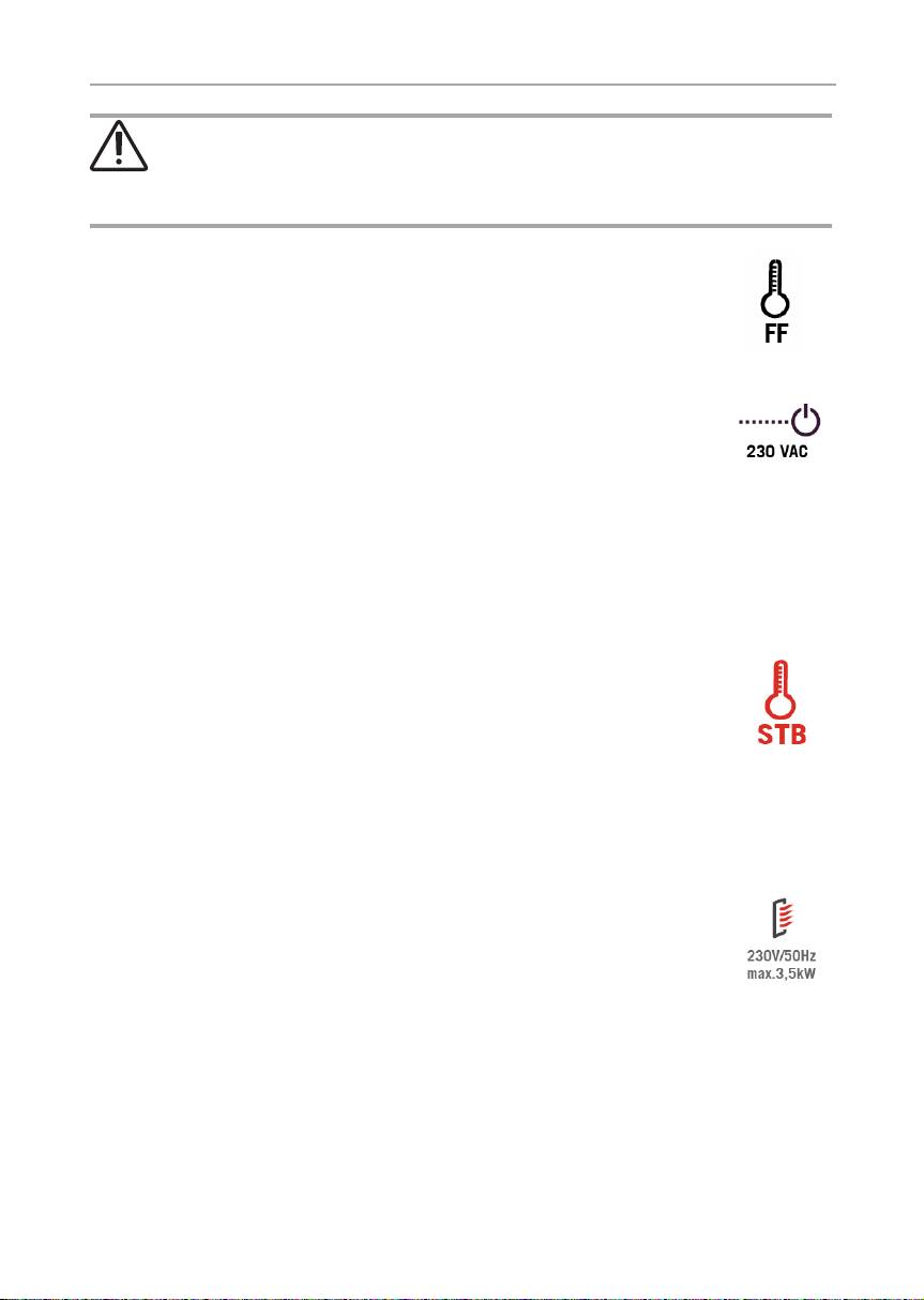
Nicht abdecken! Bedienungsanleitung lesen
Montage- und Gebrauchsanweisung S. 5/32
2. Wichtige Hinweise zu Ihrer Sicherheit
Die Infrarotsteuerung Infrabox basic ist nach anerkannten sicherheitstechnischen Regeln gebaut. Dennoch können bei der Verwendung Gefahren entstehen. Befolgen Sie deshalb die folgenden
Sicherheitshinweise und die speziellen Warnhinweise in den einzelnen Kapiteln. Beachten Sie auch die Sicherheitshinweise der
angeschlossenen Geräte.
2.1. Bestimmungsgemäßer Gebrauch
Die Infrarotsteuerung Infrabox basic dient ausschließlich zum Steuern sowie zur Bedienung der Infrarotstrahler/Infrarotplatte.
Die Infrarotsteuerung Infrabox ist für den Gebrauch mit
eigensicheren Infrarotstrahlern und Infrarotplatten geeignet.
Werden keine eigensicheren Produkte verwendet, ist der An schluss eines Sicherheitstemperaturbegrenzer (STB) erfor derlich.
DE
Beachten Sie dazu auch die Anweisungen in der jeweiligen Bedienungsanleitung. Die Infrarotsteuerung Infrabox basic darf nur zum
Steuern einer Leistung von max. 3,5 kW verwendet werden.
Übersicht Betriebsarten:
Schaltbar: bis 3,5 kW
Halbwellen-Steuerung (dimmbar): bis 1,3 kW
Phasenanschnitt (dimmbar): bis 350 W
WORLD OF WELLNESSWORLD OF WELLNESS

Montage- und Gebrauchsanweisung S. 6/32
Geeignete Infrarotstrahler: DIR-350-R, WIR-350-R, DIR-500-R,
WIR-500-R, DIR-750-R, WIR-750-R, DIR-1300-R, WIR-1300-R,
ECO-350-R, ECO-350-G, ECO-500-R, ECO-500-G, ECO-750-R,
O-IRC-W
Geeignete Infrarotplatten: IR-WP-175, IR-WP-100, IR-WP-390, IRWP-510, IR-WPHL-510, IR-WPHL-100, IR-WPHL-390, IR-WPHL-175
ACHTUNG!
Verwendung von Infrarotplatten nur in Verbindung mit dem optionalen
Folienfühler WC4-IRF-F.
● Vor der Inbetriebnahme der Steuerung ist die Kabine auf den
betriebsbereiten Zustand zu überprüfen.
● Es darf nur die im Lieferumfang enthaltene oder die optionale
Netzanschlussleitung für die Schweiz (IR-CP-CH) verwendet
werden.
● Das Leistungsteil darf nur in Verbindung mit dem im Lieferum-
fang enthaltenen Bedienteil montiert und betrieben werden.
Jeder darüber hinausgehende Gebrauch gilt als nicht bestimmungsgemäß. Nicht bestimmungsgemäßer Gebrauch kann zur Beschädigung des Produkts, zu schweren Verletzungen oder Tod führen.

Montage- und Gebrauchsanweisung S. 7/32
2.2. Sicherheitshinweise für den Monteur
● Die Montage der Klemmverbindungen darf nur durch eine Elektrofachkraft oder eine vergleichsweise qualizierte Person aus-
geführt werden.
● Die Montage der Steckverbindungen darf durch den Anwender
ausgeführt werden.
● Montage- und Anschlussarbeiten an der Infrarotsteuerung dürfen
nur im spannungsfreien Zustand durchgeführt werden.
● Beachten Sie auch die örtlichen Bestimmungen am Aufstellort.
● Stellen Sie sicher, dass keine brennbaren Gegenstände über
dem Infrarotstrahler bzw. der Infrarotplatte hängen, bevor Sie
die Infrarotsteuerung einschalten.
● Bei Problemen, die in der Montage- und Gebrauchsanweisung
nicht ausführlich genug behandelt werden, wenden Sie sich zu
Ihrer eigenen Sicherheit an Ihren Lieferanten.
DE
WORLD OF WELLNESSWORLD OF WELLNESS

Montage- und Gebrauchsanweisung S. 8/32
3. Produktbeschreibung
3.1. Lieferumfang
● Infrabox basic Bedienteil
● Infrabox basic Leistungsteil
● Netzteilanschlussleitung
● Montagematerial
● Bedienungsanleitung
● HV-Stecker
3.2. Optionales Zubehör
● Folienfühler (WC4-IRF-F) inkl. 5 m Anschlussleitung
● Stecker Infrarotstrahler (Artikelnummer: WC4-P-RA)
● Netzanschlussleitung Infrarot 2,5 m (Artikelnummer: IR-CP-EH)
● Netzanschlussleitung Infrarot 2,5 m Schweiz (Artikelnummer: IR-CP-CH)
3.3. Produktfunktionen
Die Infrarotsteuerung Infrabox verfügt über folgende Funktionen:
● Schalten der Infrarotstrahler oder Infrarotplatte mit einer Heizleistung von
max. 3,5 kW
● Steuern (dimmen) der Infrarotsteuerung in 5 Stufen mit Halbwellen-Steuerung
(bis 1,3 kW)
● Steuern (dimmen) der Infrarotsteuerung in 5 Stufen mit Phasenanschnitt (bis
350 W)
● Timer-Funktion
● Fernstartfunktion

Montage- und Gebrauchsanweisung S. 9/32
Die Infrarotsteuerung Infrabox Basic ist für den Gebrauch mit eigensicheren Infrarotstrahlern und Infrarotplatten geeignet. Werden keine
eigensichere Produkte verwendet ist der Anschluss eines Sicherheitstemperaturbegrenzers (STB) erforderlich.
● Wenn Infrarotstrahler angeschlossen werden, müssen diese über einen
Sicherheitstemperaturbegrenzer verfügen. Geeignete Infrarotstrahler siehe
2.1. Bestimmungsgemäßer Gebrauch auf Seite 5.
● Wenn Infrarotplatten angeschlossen werden, muss der Folienfühler WC4-
IRF-F verwendet und aktiviert werden (siehe 4.3. Montage FolientemperaturFühler auf Seite 13 und 5.3. Folienfühler (optional) anschließen auf Seite
16). Geeignete Infrarotplatten siehe 2.1. Bestimmungsgemäßer Gebrauch
auf Seite 5.
● Automatische Heizzeitbegrenzung
Die Infrarotsteuerung schaltet sich nach Ablauf der maximalen Heizzeit aus
Sicherheitsgründen automatisch ab (siehe auch 6.3. Laufzeit auf Seite 20).
Die EN 60335-2-53 schreibt für private Infrarotkabinen eine maximale
Heizzeitbegrenzung von 6 h vor. Für Infrarotkabinen in Hotels, Wohnblöcken und ähnlichen Standorten ist eine Heizzeitbegrenzung von
maximal 12 h zulässig. Die Erweiterung der Heizzeitbegrenzung auf
!
18 h oder 24 h ist nur in öffentlichen Infrarotkabinen gestattet.
DE
WORLD OF WELLNESSWORLD OF WELLNESS
Montageanweisung – nur für Fachpersonal S. 10/32
4. Montage
4.1. Montage Leistungsteil
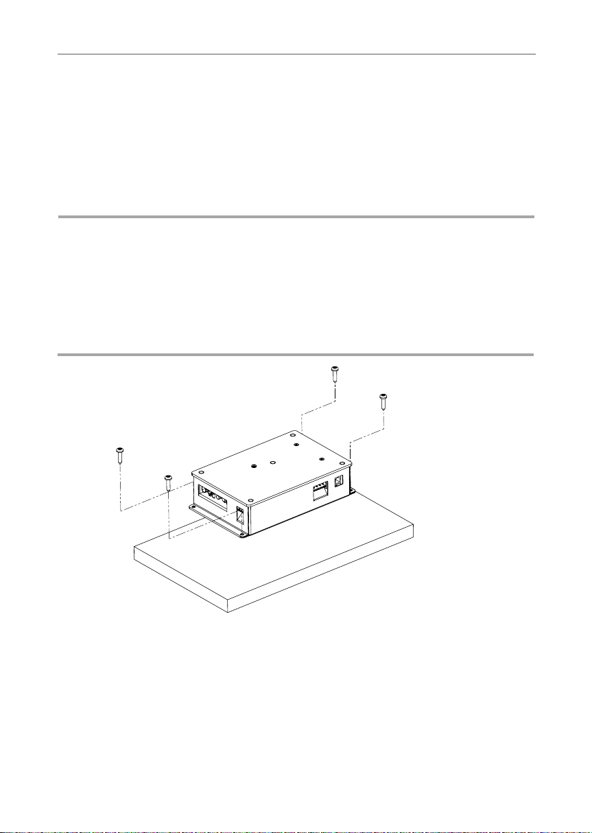
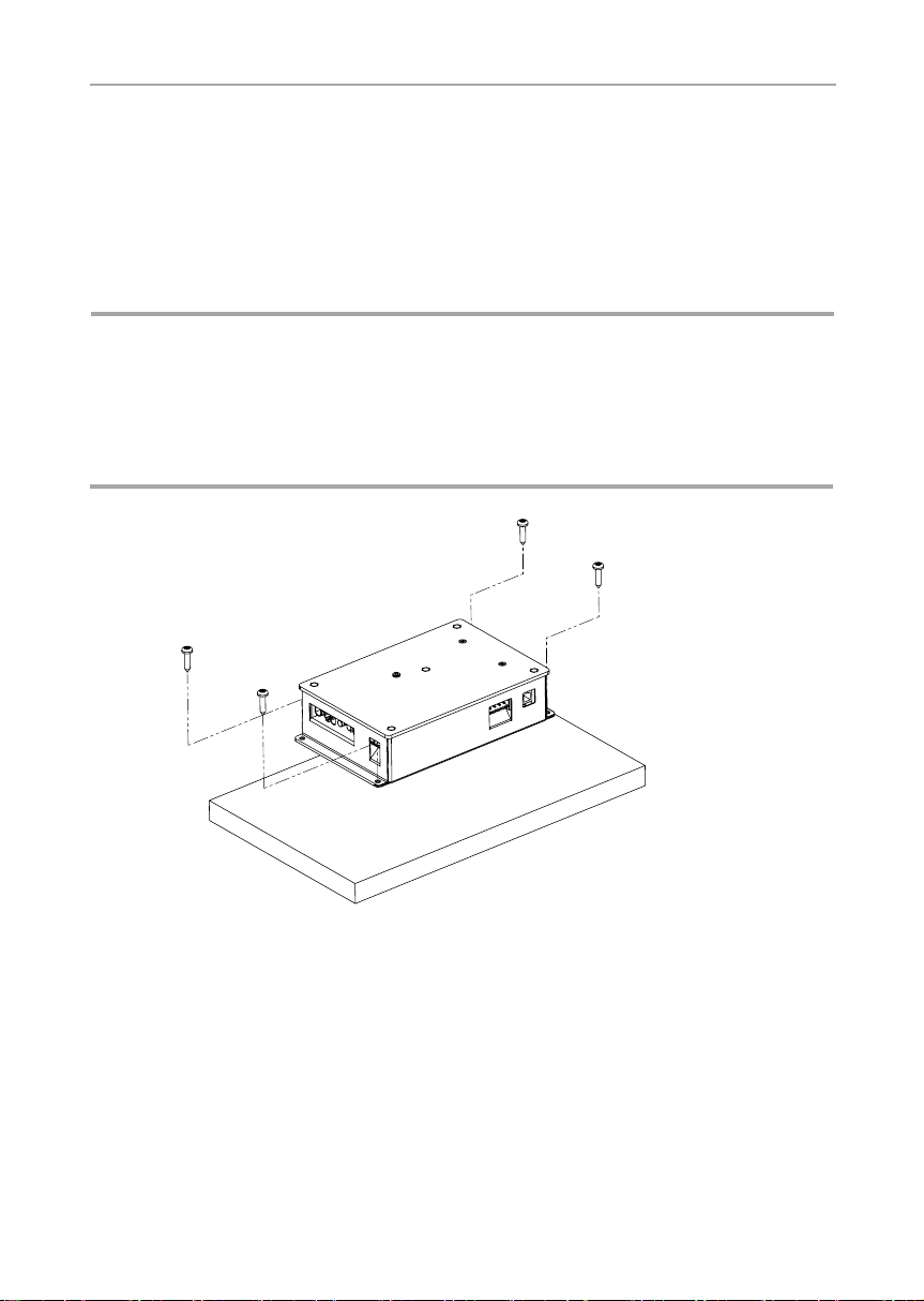
Das Leistungsteil wird auf der Kabinendecke (siehe Abb.1), an die Kabinenwand oder an einem anderen geeigneten Ort gemäß Umgebungsbedingungen
montiert. Die elektrische Versorgung erfolgt mit einer Netzanschlussleitung mit
Schutzkontaktstecker.
ACHTUNG!
Schäden am Gerät
● Montieren Sie das Leistungsteil an einem trockenen Ort. Eine maximale
Umgebungstemperatur von 40° C und eine maximale Luftfeuchte von 95 %
ist einzuhalten.
● Zur Kühlung des Leistungsteiles muss eine freie Luftzirkulation möglich sein.
Das Leistungsteil darf nicht durch Gegenstände oder Materialien abgedeckt
sein.
Abb.1 Montage Leistungsteil
1. Leistungsteil-Gehäuse Infrabox mit den vier beiliegenden Holzschrauben (16
mm Länge) an die Kabinendecke oder die Kabinenwand schrauben.
Montageanweisung – nur für Fachpersonal S. 11/32
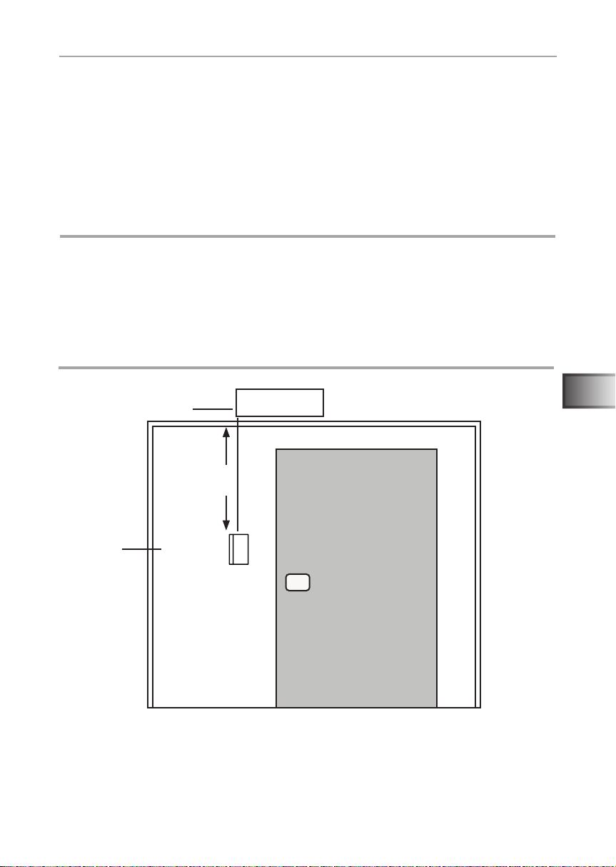
4.2. Montage Bedienteil
Das Bedienteil 2 der Infrarotsteuerung wird an der Kabinen-Außenwand im
maximalen Abstand von 10 Metern zum Leistungsteil 1 montiert (siehe Abb. 2).
Für die Montage wird beispielsweise eine handelsübliche Stichsäge benötigt um
die Ausnehmung für das Bedienteil zu schneiden. Das Bedienteil kann sowohl
in der Kabine als auch außerhalb der Kabine montiert werden.
*Bei Montage innerhalb einer Saunakabine ist ein Mindesabstand von 50 cm
zur Kabinendecke einzuhalten (siehe Abb.2 Position Bedienteil auf Seite 11).
ACHTUNG!
Schäden am Gerät
● Das Bedienteil 2 der Infrarotsteuerung ist spritzwassergeschützt (Schutz-
grad IP X4).
● Arbeiten am Bedienteil dürfen nur mit einem normalen Schraubendreher
durchgeführt werden. Bei Verwendung eines Akkuschraubers besteht die
Gefahr, dass das Gehäuse irreparabel beschädigt wird!
2
Leistungsteil
1
min. 50 cm *
Bedienteil
Abb.2 Position Bedienteil
Infrabox Basic
* bei Montage innerhalb der Kabine
Außenansicht
DE
WORLD OF WELLNESSWORLD OF WELLNESS
Montageanweisung – nur für Fachpersonal S. 12/32
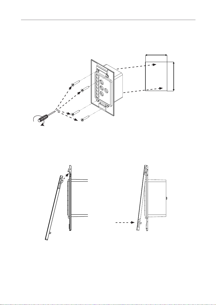
1. Mit beispielsweise einer Stichsäge die Ausnehmung 60 x 48 mm schneiden.
2. Leitungsführungen für die Verbindungsleitung vorsehen.
3. Gehäuse durch die Bohrung mit den 4 beiligenden Holzschrauben an die
Kabinenwand schrauben.
48 mm
60 mm
Abb.3 Montage Bedienteil
4. Die Frontplatte des Bedienteils wird mit leichtem Druck in das Gehäuse
eingesteckt. Achten Sie darauf, dass der untere Befestigungshaken spürbar
einrastet.
Abb.4 Montage Bedienteil
5. Verbinden Sie den 4-poligen Stecker mit der RJ11 Buchse des Bedienteils.
Montageanweisung – nur für Fachpersonal S. 13/32
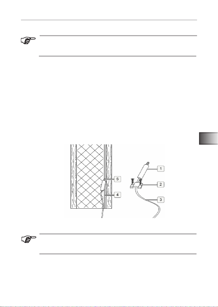
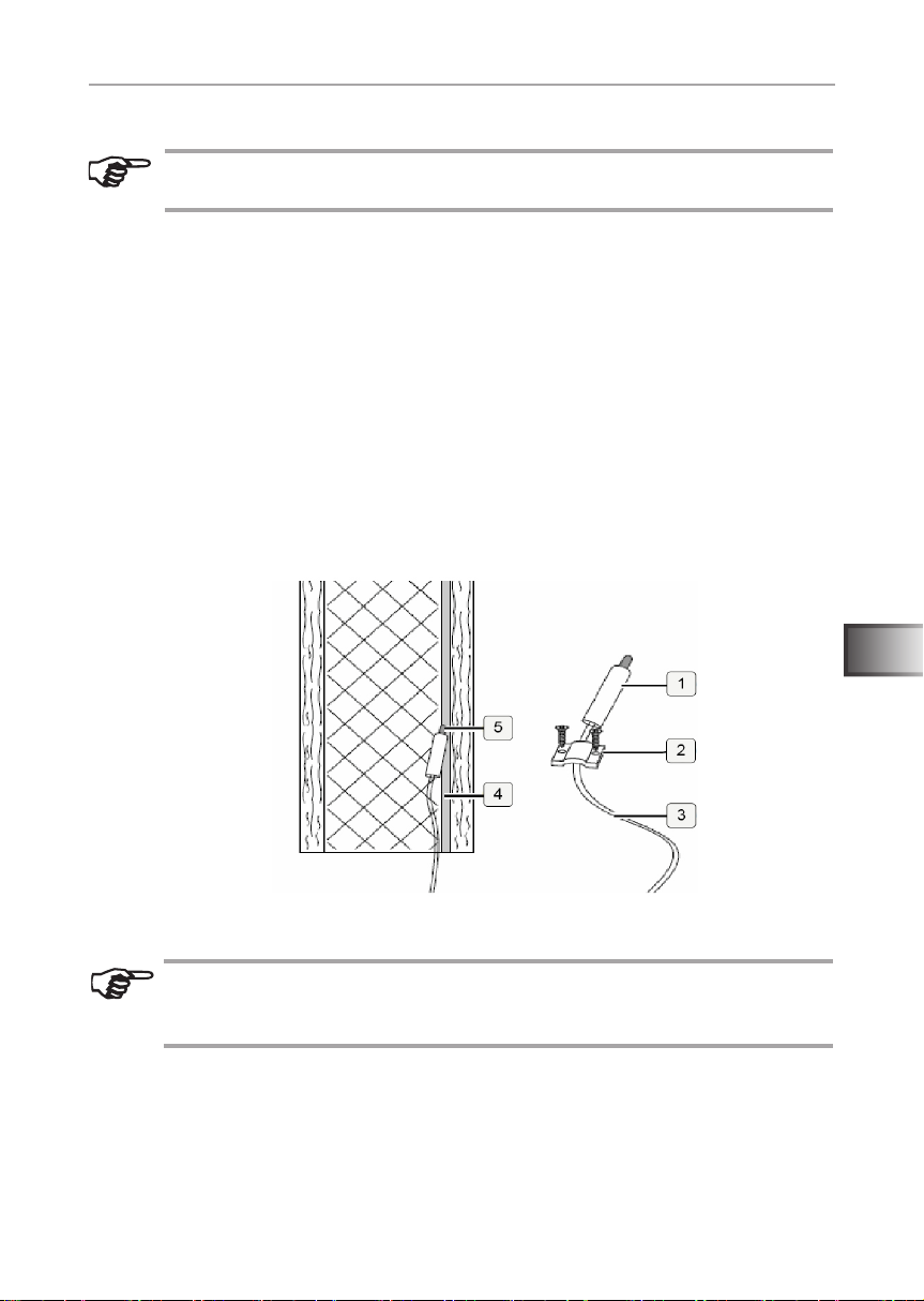
4.3. Montage Folientemperatur-Fühler
Der Folientemperatur-Fühler wird direkt an die Infrarot-Heizplatte montiert und
mit einer Zugsicherung xiert (siehe Abb. 5: Montage des Folientemperatur-
Fühlers auf Seite 13).
Den Fühlerkopf 1 des Folientemperatur-Fühlers direkt zwischen Dämmstoff
und Heizfolie 4 montieren.
Der Folientemperatur-Fühler wird nur bei Infrarotplatten-Heizsystemen
benötigt. Hier sind zusätzlich die Angaben des Platten-Heizsystemherstellers zu beachten.
1. Folientemperatur-Fühler mit der Zugentlastung 2 außerhalb des Foli-
enbereiches xieren.
2. 2-polige Leitung 3 in der Kabinenwand verlegen und mit Leitungsschel-
len xieren.
3. Die Verwendung eines Folientemperatur-Fühlers muss aktiviert werden
(6.4. Folienfühler auf Seite 21)
DE
Abb. 5: Montage des Folientemperatur-Fühlers
Wird der Folientemperatur-Fühler nicht direkt an die Infrarotplatte montiert, kommt es zu falschen Messwerten. Den Folientemperatur-Fühler
direkt an die Folie montieren.
WORLD OF WELLNESSWORLD OF WELLNESS

Montageanweisung – nur für Fachpersonal S. 14/32
5. Elektrischer Anschluss
Beachten Sie beim elektrischen Anschluss der Infrarotsteuerung folgende Punkte:
● Arbeiten an der Infrarotsteuerung dürfen nur im spannungsfreien Zustand
durchgeführt werden.
Das Anschließen aller Komponenten an dem Infrabox Basic Leistungsteil erfolgt
gemäß nachfolgender Abbildungen:
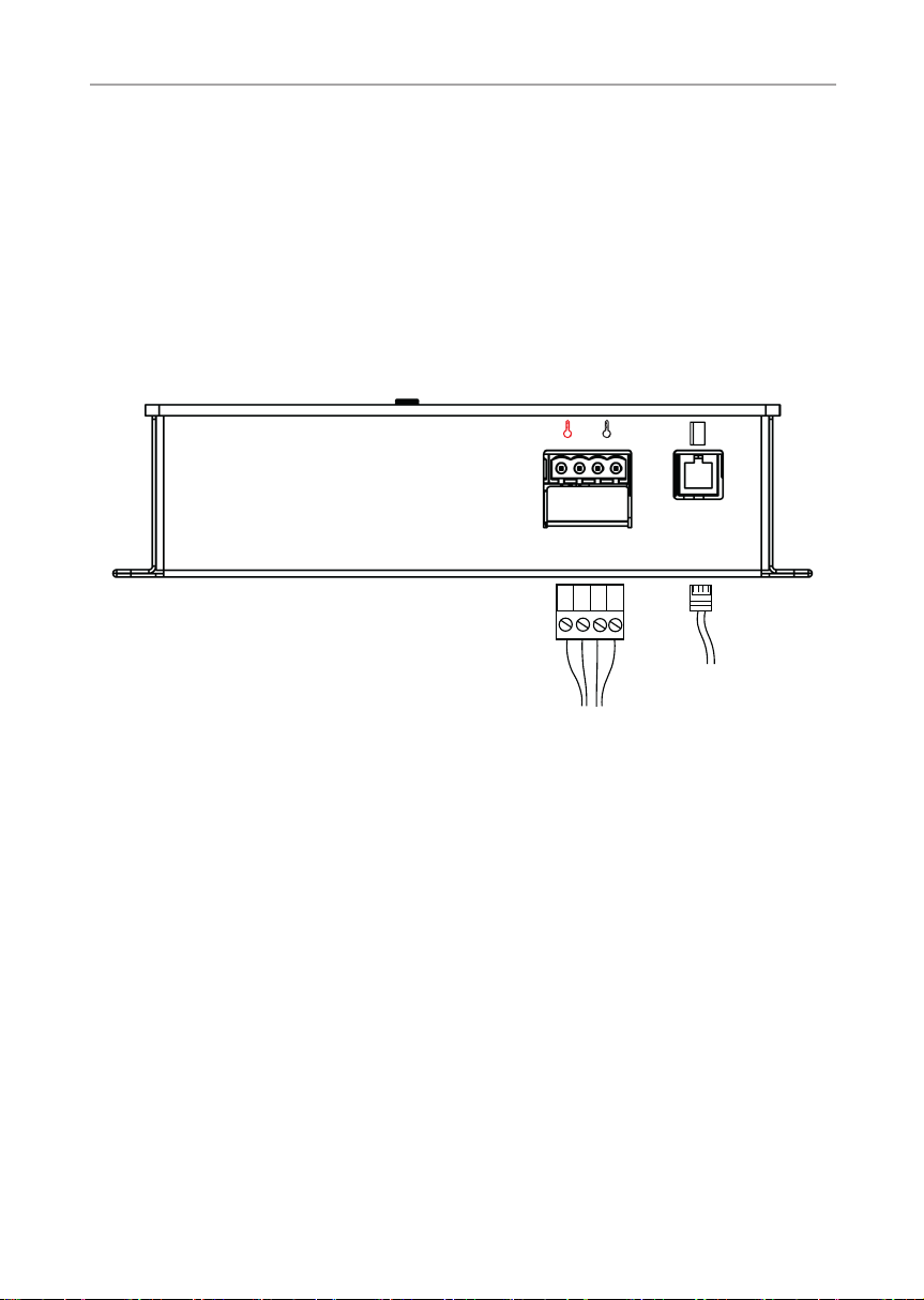
5.1. Anschlussbereich für Fühler/Bedienteil
STB FF
Abb. 6: Anschlussbereich Fühler/Bedienteil
1 Folientemperatur-Fühler (FF)
Sicherheitstemperaturbegrenzer (STB)
2 Infrabox-Bedienteil
1
2
Montageanweisung – nur für Fachpersonal S. 15/32
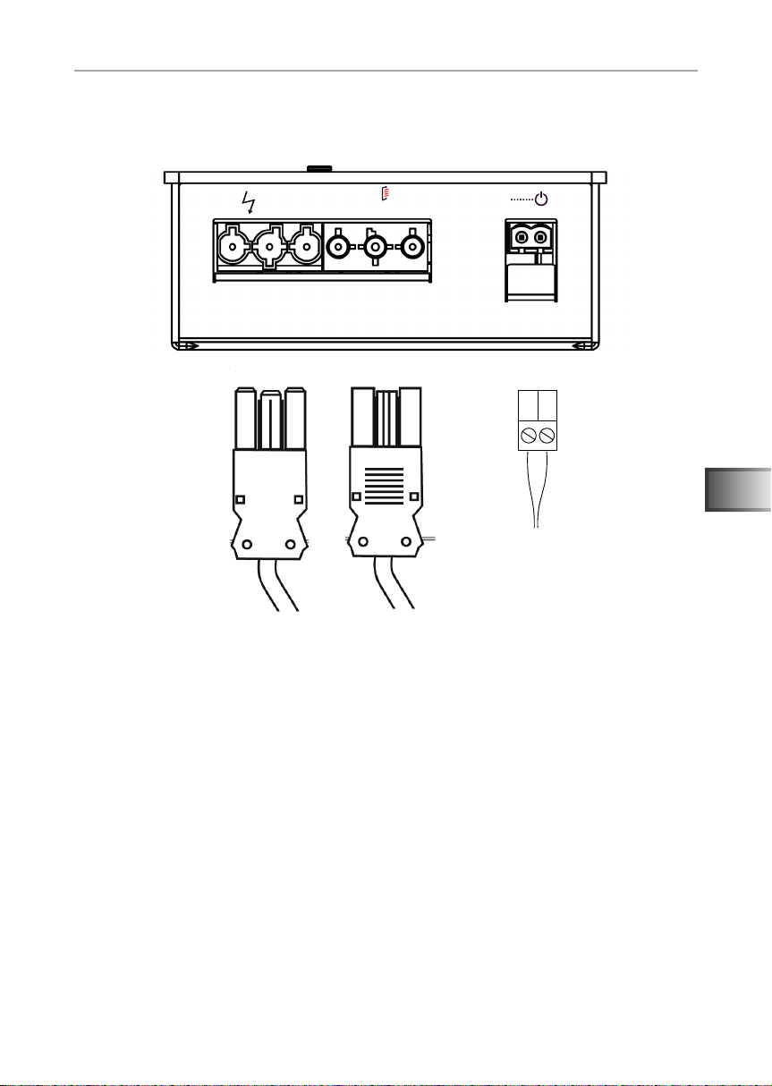
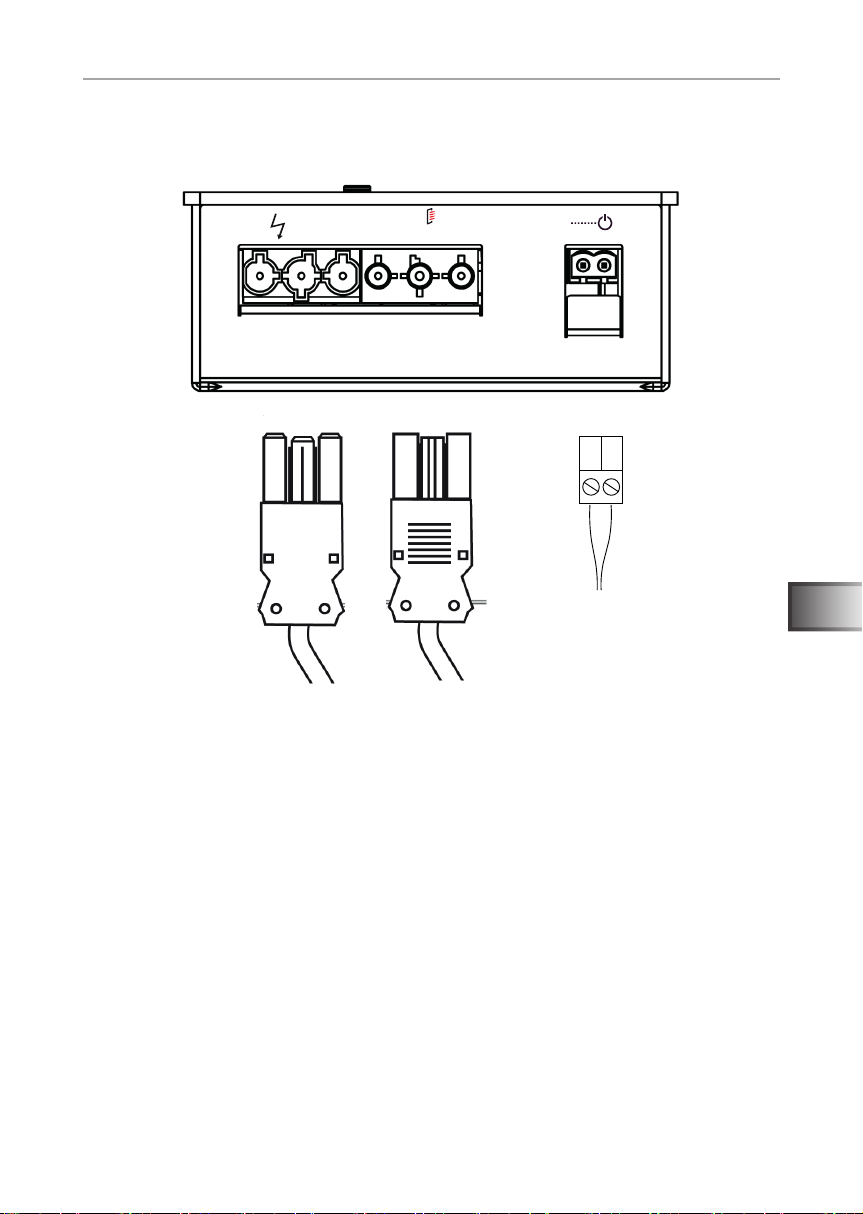
5.2. Anschlussbereich für 230 V
230V/50Hz
max.16A
3 4 5
230V/50Hz
max.3,5kW
230 VAC
DE
Abb. 7: Anschlussbereich für 230 V
3 Netzanschluss 230 V / 50 Hz max. 16 A
4 Infrarotstrahler max. 3,5 kW
5 Fernstart (230 V / 50 Hz)
WORLD OF WELLNESSWORLD OF WELLNESS
Montageanweisung – nur für Fachpersonal S. 16/32
WARNUNG!
Personenschaden
● Die Montage der Klemmverbindungen darf nur durch eine Elektrofach-
kraft oder eine vergleichsweise qualizierte Person ausgeführt werden.
5.3. Folienfühler (optional) anschließen
Folienfühlerleitung an den 2-polige Folienfühlerstecker gemäß Abb. 6:
Anschlussbereich Fühler/Bedienteil auf Seite 14 an FF anklemmen.
5.4. HV-Eingang (Freischalteingang) anschließen
Der Eingang wird durch Anlegen von Wechselspannung (230 V /
50 Hz) aktiv. Angeschlossen wird der Eingang mittels 2-poligen HVStecker gemäß Abb. 7: Anschlussbereich für 230 V auf Seite 15.
Die genaue Schrittfolge zur Aktivierung entnehmen Sie bitte dem
Kapitel 6.7. HV-Eingang (Freischalteingang) auf Seite 24.
5.5. Sicherheitstemperaturbegrenzer (STB) anschließen (optional)
Bei Verwendung von Infrarotstrahlern und Infrarotplatten ohne Eigensicherung ist der Anschluss eines Sicherheitstemperaturbegrenzer
(STB) notwendig!
Die STB Anschlussleitung erfolgt gemäß Abb. 6: Anschlussbereich
Fühler/Bedienteil auf Seite 14 an den STB Anschluss.
5.6. Infrarotstrahler / Infrarotplatte anschließen
Infrarotstrahler/Infrarotplatte an den vorgesehenen Anschluss gemäß
Abb. 7: Anschlussbereich für 230 V auf Seite 15 anschließen. Bitte
beachten Sie dazu auch die Anweisungen in der jeweiligen Bedienungsanleitung.
Montageanweisung – nur für Fachpersonal S. 17/32
ON
OFF
DIP-Bank 4 DIP-Bank 3 DIP-Bank 2 DIP-Bank 1
6. Inbetriebnahme
Standardmäßig sind alle Funktionswahlschalter auf OFF gestellt.
Abb. 8: Funktionswahlschalter - Standardeinstellung
Jede DIP-Bank hält Einstellungsoptionen für die Produktfunktionen der Infrabox
Basic bereit, welche nachfolgend angeführt und detailiert beschrieben sind.
In jeder Funktionseinstellung wird auf die DIP-Bank, sowie den Funktionswahlschalter hingewiesen in der die Einstellungen vorgenommen werden können.
Bitte beachten Sie, dass nach Einstellungsänderungen die Steuerung
für 10 Sek. vom Netz getrennt werden muss, um die Einstellungen zu
speichern.
Im standardmäßige Auslieferungszutand sind die Funktionen wie folgt:
Betriebsmodus: Normal
Betriebsart: Schalten
Laufzeit: 6h
Fohlienfühler: Aus
Phasen An- / Abschnitt: Nicht aktiviert
DE
WORLD OF WELLNESSWORLD OF WELLNESS
Montageanweisung – nur für Fachpersonal S. 18/32
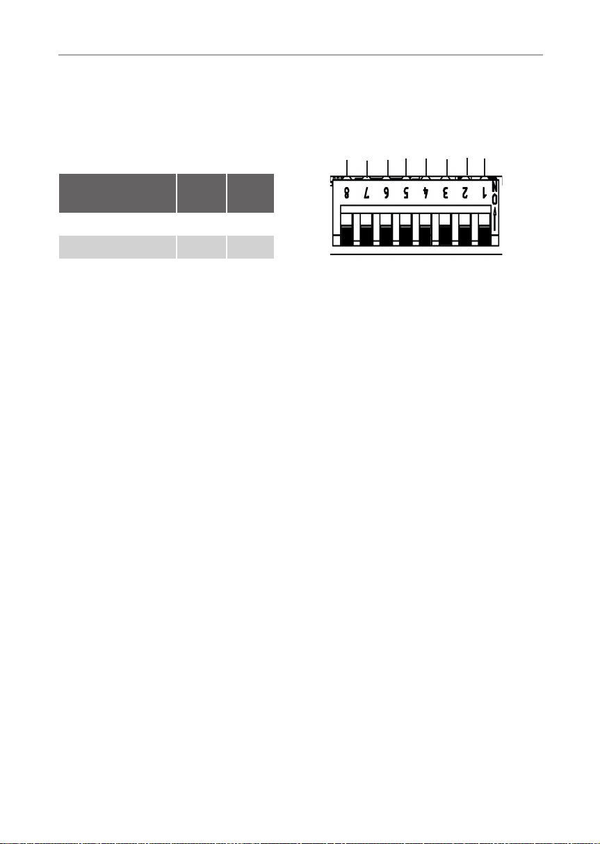
6.1. Betriebsmodus
DIP-Bank 1
Funktionswahlschalter 1 und 2
Im Betriebsmodus sind folgende Einstellungen möglich:
Laufzeit
Laufzeit
Laufzeit
Laufzeit
Infra
Betriebs-
Infra
Betriebs-
mode
mode
Funktionswahl-
schalter
Normal OFF OFF
1 2
ON
OFF
Timer I/0 ON OFF
Abb. 9: Betriebsmodus
Normal: Infrarotstrahler/Infrarotplatte schaltbar oder dimmbar.
Die Aktivierung der Dimmfunktion der Infrarotstrahler/Infrarotplatten erfolgt über
die Infra-Ansteuerung siehe 6.2. Betriebsart (Infrarotstrahler/Infrarotplatte) auf
Seite 19.
Timer I/0 (Ein/Aus): im Betriebsmodus Ein/Aus schaltet sich die Steuerung
nach Ablauf der eingestellten Ein-Zeit Zeit aus und wird nicht erneut aktiviert.
Infrarotstrahler/Infrarotplatte schaltbar.
Weitere Einstellungen siehe 6.5. Ein-Zeit (Timer I/0) auf Seite 22 sowie Abb.
15: Betriebsmodus Timer I/0 auf Seite 23.
Montageanweisung – nur für Fachpersonal S. 19/32
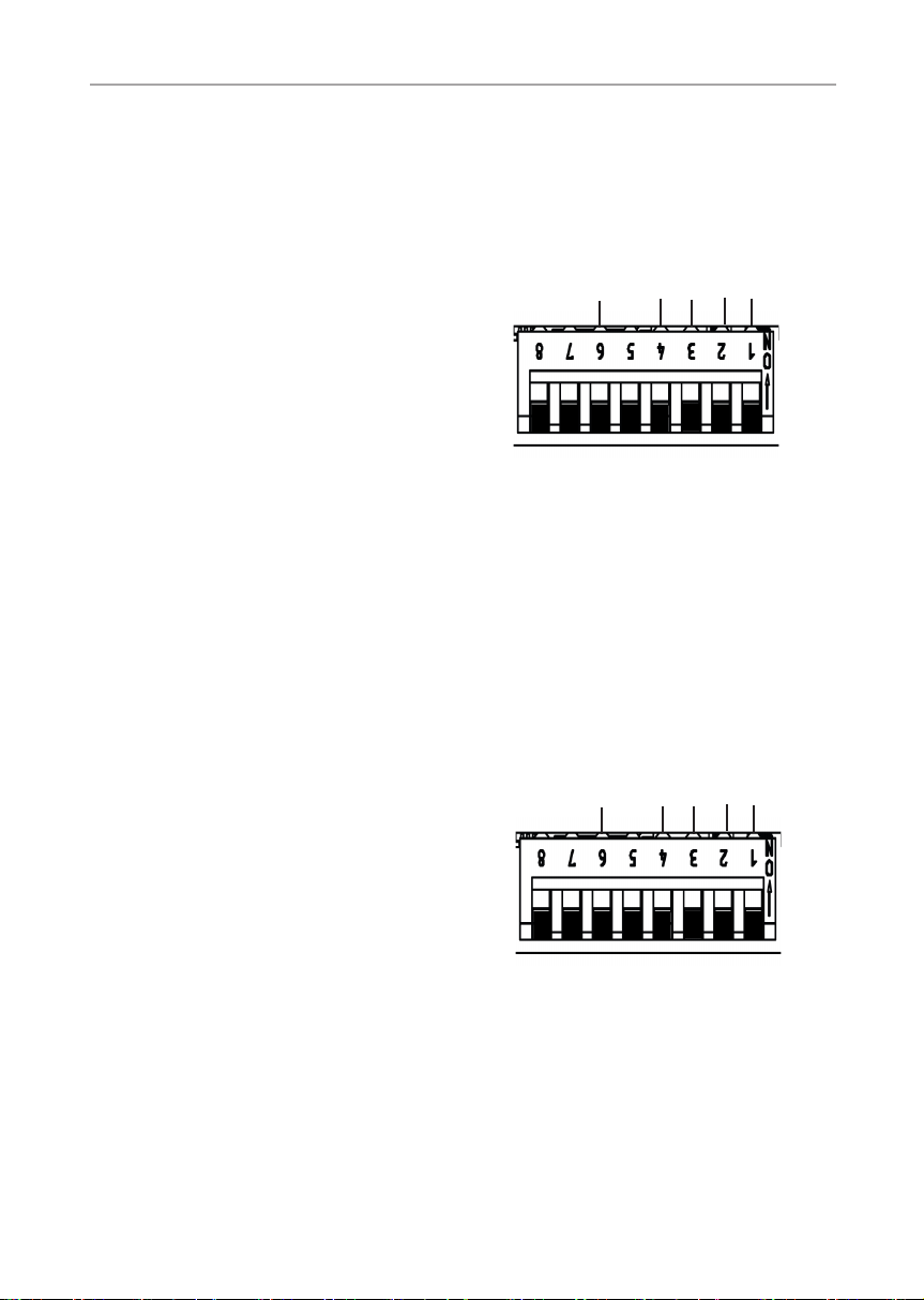
6.2. Betriebsart (Infrarotstrahler/
Infrarotplatte)
DIP-Bank 1
Funktionswahlschalter 3 und 4
Bei der Infra-Ansteuerung sind folgende Einstellungen möglich:
Funktionswahl-
schalter
Schalten OFF OFF
Phasenanschnitt ON OFF
Halbwellen-Steuerung OFF ON
ACHTUNG!
Die angegebenen Leistungsgrenzen dürfen nicht überschritten werden!
3 4
Laufzeit
Laufzeit
Abb. 10: Betriebsart Infra
Laufzeit
Laufzeit
Infra
Betriebs-
Infra
Betriebs-
mode
mode
ON
OFF
Um eine optimale Funktionalität zu gewährleisten, empfehlen wir die Funktion
Phasenanschnitt für Infrarotstrahler mit sichtbarem Licht. Die Funktion HalbwellenSteuerung ist für Infrarotplatten und Infrarotstrahler ohne sichtbarem Licht geeignet.
Schalten: Schalten der Infrarotstrahler oder Infrarotplatte mit einer Heizleistung
von max. 3,5 kW. Keine Dimmfunktion.
Phasenanschnitt: Steuern (dimmen) der Infrarotstrahler/Infrarotplatte in 5 Stufen
möglich bis 350 W.
Halbwellen-Steuerung: Steuern (dimmen) der Infrarotstrahler/Infrarotplatte in
5 Stufen möglich bis 1,3 kW.
DE
WORLD OF WELLNESSWORLD OF WELLNESS
Montageanweisung – nur für Fachpersonal S. 20/32
6.3. Laufzeit
DIP-Bank 1
Funktionswahlschalter 5 - 8
Die maximale Laufzeit ist standardmäßig
auf 6 h eingstellt. Die Infrarotsteuerung
schaltet sich nach Ablauf der maximalen
Laufzeit aus Sicherheitsgründen automatisch ab.
Über die Funktionswahlschalter im Anschlussbereich für Kleinspannung kann
die maximale Laufzeit angepasst werden.
Die dafür erforderliche Position der Funkti-
onswahlschalter nden Sie in der folgenden
Tabelle.
Die EN 60335-2-53 schreibt für private Saunen eine maximale Heizzeitbegrenzung von 6 h vor. Für Saunen in Hotels, Wohnblöcken und
ähnlichen Standorten ist eine Heizzeitbegrenzung von maximal 12 h
zulässig. Die Erweiterung der Heizzeitbegrenzung auf 18 h oder 24 h
!
ist nur in öffentlichen Saunen gestattet.
Laufzeit
Laufzeit
Laufzeit
Laufzeit
Abb. 11: Laufzeit
Infra
Betriebs-
Infra
Betriebs-
mode
mode
ON
OFF
Zeit
5 min ON ON ON ON
10 min OFF ON ON ON
15 min ON OFF ON ON
30 min ON ON OFF ON
45 min OFF ON OFF ON
60 min ON OFF OFF ON
Funktionswahlschalter
5 6 7 8
Montageanweisung – nur für Fachpersonal S. 21/32
Zeit
Funktionswahlschalter
5 6 7 8
2 h OFF OFF OFF ON
3 h ON ON ON OFF
4 h OFF ON ON OFF
5 h ON OFF ON OFF
6 h OFF OFF OFF OFF
12 h ON OFF OFF OFF
18 h OFF ON OFF OFF
24 h ON ON OFF OFF
6.4. Folienfühler
DIP-Bank 4
Funktionswahlschalter 3
Wenn an den Infrarotausgang Infrarotplatten angeschlossen werden, muss der
Folienfühler WC4-IRF-F verwendet werden.
Der Folienfühler muss laut nebenstehender
Abbildung durch die Stellung des Schalters
3 auf ON aktiviert werden.
Phasen
Fernstart-
aktivierung
Nicht belegt
Nicht belegt
Folien-Fühler
An-/Abschnitt
DE
ON
OFF
Abb. 12: Folienfühler
WORLD OF WELLNESSWORLD OF WELLNESS
Montageanweisung – nur für Fachpersonal S. 22/32
6.5. Ein-Zeit (Timer I/0)
DIP-Bank 2
Funktionswahlschalter 3 - 6
Hinweis: Zur Aktivierung der Ein-Zeit sind
weitere Einstellungen erforderlich siehe 6.1.
sec/min
x10
Ein-Zeit
Ein-Zeit
Ein-Zeit
Betriebsmodus auf Seite 18 sowie Abb.
15: Betriebsmodus Timer I/0 auf Seite 23.
Abb. 13: Ein-Zeit
Funktion der Ein-Zeit: der Ausgang beginnt nach Einschalten der Steuerung
gemäß den eingestellten Zeiten zu laufen bzw. zu takten.
Ein-Zeit: Einstellen der Zahl (Timerfunktion). Schalterposition des gewünschten
Wertes auf ON laut folgender Tabelle.
x10 - Multiplikator (7): Die über die Werte eingestellte Zahl wird mit 10 multipliziert.
OFF = deaktiviert, ON = aktiviert
sec/min - Einheit (8): Umschalten von Sekunden auf Minuten.
OFF = Sekunden, ON = Minuten
Sitzplatz-Zeit
Ein-Zeit
Sitzplatz-Zeit
ON
OFF
Beispiel: Einstellzeit 3 min
x10
Ein-Zeit
Ein-Zeit
sec/min
Sitzplatz-Zeit
Ein-Zeit
Ein-Zeit
Abb. 14: Beispiel Ein-Zeit
Sitzplatz-Zeit
ON
OFF

Montageanweisung – nur für Fachpersonal S. 23/32
Zeit
Funktionswahlschalter
6 5 4 3
1 OFF OFF OFF OFF
2 OFF OFF OFF ON
3 OFF OFF ON OFF
4 OFF OFF ON ON
5 OFF ON OFF OFF
6 OFF ON OFF ON
7 OFF ON ON OFF
8 OFF ON ON ON
9 ON OFF OFF OFF
10 ON OFF OFF ON
11 ON OFF ON OFF
12 ON OFF ON ON
13 ON ON OFF OFF
14 ON ON OFF ON
15 ON ON ON OFF
16 ON ON ON ON
DE
Betriebsmodus Timer I/0 (Ein/Aus): im Betriebsmodus Ein/Aus schaltet sich
die Steuerung nach Ablauf der eingestellten Ein-Zeit Zeit aus und wird nicht
erneut aktiviert.
Gesamtlaufzeit (siehe 6.3 Laufzeit)
EIN
Ein-Zeit
AUS
Abb. 15: Betriebsmodus Timer I/0
WORLD OF WELLNESSWORLD OF WELLNESS

Montageanweisung – nur für Fachpersonal S. 24/32
6.6. Phasen An-/Abschnitt
DIP-Bank 4
Funktionswahlschalter 4
Einstellmöglichkeiten:
Phasenanschnitt: OFF (Standard)
Fernstart-
An-/Abschnitt
aktivierung
Nicht belegt
Nicht belegt
Folien-Fühler
Phasen
Phasenabschnitt: ON
Zur Aktivierung des Phasen An-/Abschnitts
sind weitere Einstellungen erforderlich siehe
ON
6.1. Betriebsmodus auf Seite 18.
OFF
Funktion verfügbar im Modus Normal.
Abb. 16: Phase An-/Abschnitt
Wird die Betriebsart Phasenanschnitt (siehe 6.2. Betriebsart (Infrarotstrahler/
Infrarotplatte) auf Seite 19) gewählt, besteht die Möglichkeit zwischen Phasen
An-/Abschnitt zu wählen.
6.7. HV-Eingang (Freischalteingang)
DIP-Bank 4
Funktionswahlschalter 6
Freischalteingang (ON-Stellung)
Steuerung kann nur eingeschalten werden,
wenn am HV-Eingang 230 VAC anliegen.
Diese Funktion kann beispielsweise in Kombination mit einem Münzautomat genutzt
werden.
Siehe auch 5.4. HV-Eingang (Freischalteingang) anschließen auf Seite 16.
Phasen
HV-Eingang
An-/Abschnitt
Abb. 17: HV-Eingang
Nicht belegt
Nicht belegt
Folien-Fühler
ON
OFF

Montageanweisung – nur für Fachpersonal S. 25/32
7. Prüfungen durchführen
Die folgenden Prüfungen müssen von einem zugelassenen Elektroinstallateur
durchgeführt werden.
WARNUNG!
Die folgenden Prüfungen werden bei eingeschalteter Stromversorgung durchgeführt. Es besteht die Gefahr eines Stromschlages.
● Berühren Sie NIEMALS spannungsführende Teile.
1. Prüfen Sie den Kontakt der Erdungsleitungen an der Schutzleiterklemme.
2. Bei Verwendung eines Folienfühlers (siehe Abb. 6: Anschlussbereich Fühler/
Bedienteil auf Seite 14)
a. Stecken Sie den Fühler aus. Fehlercode 3 (siehe 11.1. Fehlermeldungen
auf Seite 30) wird angezeigt.
b. Wird der richtige Fehlercode angezeigt, stecken Sie den Fühler wieder an.
3. Bei Verwendung eines Sicherheitstemperaturbegrenzer (STB) (siehe Abb.
6: Anschlussbereich Fühler/Bedienteil auf Seite 14)
a. Stecken Sie den Sicherheitstemperaturbegrenzer (STB) aus. Fehler-
code 2 (siehe 11.1. Fehlermeldungen auf Seite 30) wird angezeigt.
b. Wird der richtige Fehlercode angezeigt, stecken Sie den STB wieder an.
4. Bei Verwendung von Infrarotplatte/Infrarotstrahler (siehe Abb. 7: Anschlussbereich für 230 V auf Seite 15)
a. Überprüfen Sie diese auf Funktionalität.
DE
WORLD OF WELLNESSWORLD OF WELLNESS

Gebrauchsanweisung für den Anwender S. 26/32
8. Sicherheitshinweise für den Anwender
● Die Infrarotsteuerung darf nicht von Kindern unter 8 Jahren
verwendet werden.
● Die Infrarotsteuerung darf von Kindern über 8 Jahren, von Per-
sonen mit verringerten psychischen, sensorischen oder mentalen
Fähigkeiten und von Personen mit Mangel an Erfahrung und
Wissen unter folgenden Bedingungen verwendet werden:
– wenn sie beaufsichtigt werden
– wenn ihnen die sichere Verwendung gezeigt wurde und sie
die Gefahren, die entstehen können, verstehen.
● Kinder dürfen nicht mit dem Gerät spielen.
● Kinder unter 14 Jahren dürfen das Gerät nur reinigen, wenn sie
beaufsichtigt werden.
● Wenn Sie unter dem Einuss von Alkohol, Medikamenten oder
Drogen stehen, verzichten Sie aus gesundheitlichen Gründen
auf die Benutzung der Infrarotkabine.
● Stellen Sie sicher, dass keine brennbaren Gegenstände über
dem Infrarotstrahler bzw. der Infrarotplatte hängen, bevor Sie
die Infrarotsteuerung einschalten.
● Bei Problemen, die in der Gebrauchsanweisung nicht ausführ-
lich genug behandelt werden, wenden Sie sich zu Ihrer eigenen
Sicherheit an Ihren Lieferanten.

Gebrauchsanweisung für den Anwender S. 27/32
9. Bedienung
9.1. Bezeichnung Bedienelemente
1
2
5
3
4
DE
1 Intensität erhöhen/
Betriebsmodus Normal: Ein
2 Intensität verringern/
Betriebsmodus Normal: Aus
3 EIN/AUS-Taster
WORLD OF WELLNESSWORLD OF WELLNESS
4 Betriebsanzeige
5 Intensitätsanzeige/
Ein/Aus Anzeige

Gebrauchsanweisung für den Anwender S. 28/32
WARNUNG!
Brandgefahr
● Stellen Sie sicher, dass keine brennbaren Gegenstände über dem
Infrarotstrahler bzw. der Infrarotplatte hängen, bevor Sie die Infrarotsteuerung einschalten.
9.2. Infrarotsteuerung einschalten
1. Drücken Sie den EIN/AUS-Taster 3, um die Infrarotsteuerung einzuschalten.
► Die Betriebsanzeige 4 leuchtet.
2. Wählen Sie mit dem Intensitäts-Wähler 1 und 2 die gewünschte Intensität
der Funktion.
► Der Infrarotstrahler/die Infrarotplatte beginnt zu heizen.
9.3. Dimmfunktion Infrarotstrahler / Infrarotplatte
Steuern (dimmen) der Infrarotstrahler/Infrarotplatte in 5 Stufen möglich. Beim
Wert 0 ist der Infrarotstrahler/die Infrarotplatte ausgeschalten, Wert 5 entspricht
der vollen Leistung.
Funktion nur möglich in Betriebsarten: Phasenanschnitt und Halbwellensteuerung
Zur Aktivierung der Funktion sind weitere Einstellungen erforderlich siehe Kapitel
6.2. Betriebsart (Infrarotstrahler/Infrarotplatte) auf Seite 19.
Funktion nur möglich in Betriebsmodus: Normal und Sitzplatz
Zur Aktivierung der Funktion sind weitere Einstellungen erforderlich siehe Kapitel
6.1. Betriebsmodus auf Seite 18.
1. Stellen Sie mit den Intensitäts-Wähler 1 und 2 die gewünschte Infrarot-
strahler-/Infrarotplatten-Intensität ein.
► Die Infrarotstrahler / Infrarotplatte wird eingeschalten.
► Die Intensitäts-Anzeige 5 leuchet.

Gebrauchsanweisung für den Anwender S. 29/32
10. Reinigung und Wartung
10.1. Reinigung
ACHTUNG!
Schäden am Gerät
Die Infrabox ist spritzwassergeschützt, trotzdem kann direkter Kontakt mit Wasser
das Gerät beschädigen.
● Tauchen Sie das Gerät NIEMALS in Wasser.
● Übergießen Sie das Gerät nicht mit Wasser.
● Reinigen Sie das Gerät nicht zu feucht.
1. Tränken Sie ein Reinigungstuch in milder Seifenlauge.
2. Drücken Sie das Reinigungstuch gut aus.
3. Wischen Sie das Gehäuse der Infrarotsteuerung vorsichtig ab.
10.2. Wartung
Die Infrarotsteuerung ist wartungsfrei.
DE
WORLD OF WELLNESSWORLD OF WELLNESS

Montageanweisung – nur für Fachpersonal S. 30/32
11. Problemlösung
11.1. Fehlermeldungen
Die Infrabox Basic ist mit einer Diagnosesoftware ausgestattet, die beim Einschalten und im Betrieb die Systemzustände überprüft. Sobald die Diagnosesoftware
einen Fehler erkennt, schaltet die Steuerung den Infrarotausgang aus.
Fehler werden durch Blinken der LEDs angezeigt.
Schalten Sie die Infrarotsteuerung mit dem EIN/AUS-Schalter 3 (siehe 9.1. Bezeichnung Bedienelemente auf Seite 27) aus, trennen Sie das Kabel vom Netz
und beheben Sie den Fehler bevor Sie die Infrarotsteuerung wieder einschalten.
Die folgende Tabelle beschreibt die möglichen Fehler und deren Ursache. Bei
Bedarf teilen Sie die Anzahl der leuchtenden LEDs Ihrem Kundendienst mit.
An-
zahl-
LED
1 Allgemein Bitte wenden Sie sich an den Kun-
2 Sicherheitstemperaturbegren-
zer (STB) Bruch
3 Folien-Temperaturfüler gebro-
chen oder Kurzschluss
Fehler Ursache / Behebung
densupport.
Sicherheitstemperaturbegrenzer
überprüfen oder Brücke in Klemme
STB setzen.
Defekter Temperaturfühler oder
schlechter Kontakt oder Kurzschluss
4 Folienfühler-Übertemperatur Die maximale Folientemperatur von
100° C wurde überschritten. Fühler
muss via DIP aktiviert werden.
5 Kommunikationsfehler zwi-
schen Bedienteil und Leistungsteil
Schlechter Kontakt oder defektes Verbindungskabel. Bitte wenden Sie sich
an den Kundensupport.
Gebrauchsanweisung für den Anwender S. 31/32
12. Entsorgung
● Entsorgen Sie die Verpackungsmaterialien nach den gültigen
Entsorgungsrichtlinien.
● Altgeräte enthalten wiederverwendbare Materialien, aber auch
schädliche Stoffe. Geben Sie Ihr Altgerät deshalb auf keinen Fall
in den Restmüll, sondern entsorgen Sie das Gerät nach den örtlich
geltenden Vorschriften.
DE
WORLD OF WELLNESSWORLD OF WELLNESS

Montage- und Gebrauchsanweisung S. 32/32
13. Technische Daten
Bedienteil
Anschluss: 4-polig mit Versorgungs- und Kommunikationsleitungen
Netzspannung: 5 VDC
Leistung: <0,5 W
Lagertemperatur: -25° C bis +70° C
Umgebungstemperatur: -10° C bis +110° C
Luftfeuchtigkeit: max. 99% r e l. Fe uchte ,
nicht kondensierend!
Abmessung: L x B x T 100,1 x 63,1x 36,6 mm
Leistungsteil
Nennspannung 230 VAC
Abmessung 195 x 119 x 48 mm
Anschlussleitung 3 x 1,5 mm² für Licht,
Elektronik und Heizelemente
Schaltleistung / Heizgerät
Phasenanschnitt 350 W
Halbwellensteuerung 1,3 kW
Schalten 3,5 kW
Umgebungsbedignungen 10° C bis +40° C
Licht-/Lüfterleistung 100 W
Thermische Sicherheit
Automatische Heizzeitbegrenzung einstellbar (6 h, 12 h, 18 h, 24 h)*
* Die EN 60335-2-53 schreibt für private Saunen eine Heizzeitbegrenzung von 6 h vor. Für Saunen
in Hotels, Wohnblöcken und ähnlichen Standorten ist eine Heizzeitbegrenzung von 12 h zulässig.
Die Erweiterung der Heizzeitbegrenzung auf 18 h oder 24 h ist nur in öffentlichen Saunen gestattet.
WORLD OF WELLNESS

Infrared controller
infrabox basic /
infrabox basic white
INSTRUCTIONS FOR INSTALLATION AND USE
English
EN
Version 06/16 ID no. 1-035-673

Table of Contents
1. About this instruction manual 4
2. Important information for your safety 5
2.1. Intended use 5
2.2. Safety information for the installer 7
3. Product description 8
3.1. Scope of delivery 8
3.2. Optional accessories 8
3.3. Product functions 8
4. Installation 10
4.1. Installing the power supply unit 10
4.2. Installing the control unit 11
4.3. Installing the foil temperature sensor 13
5. Electrical connection 14
5.1. Connection area for sensor/control unit 14
5.2. Connection diagram for 230 V 15
5.3. Connecting the foil sensor (optional) 16
5.4. Connecting the HV input (enable input) 16
5.5. Connecting the safety temperature limiter (optional) 16
5.6. Connecting the infrared heater / infrared plate 16
6. Starting up 17
6.1. Operating mode 18
6.2. Operating type (infrared heater/infrared plate) 19
6.3. Operating time 20
6.4. Foil sensor 21
6.5. On-time (I/0 timer) 22
6.6. Leading/trailing edge phase control 24
6.7. HV input (enable input) 24

7. Performing tests 25
8. Safety information for the user 26
9. Operation 27
9.1. Description of control elements 27
9.2. Switching the infrared controller 28
9.3. Dimming function for the infrared heater/infrared plate 28
10. Cleaning and maintenance 29
10.1. Cleaning 29
10.2. Maintenance 29
11. Troubleshooting 30
11.1. Error messages 30
12. Disposal 31
13. Technical data 32
WORLD OF WELLNESSWORLD OF WELLNESS
EN

Instructions for installation and use p. 4/32
1. About this instruction manual
Read these installation and operating instructions carefully and keep them within
reach when using the infrared controller. This ensures that you can refer to information about your safety and the operation at any time.
These installation and operating instructions can also be found in the
downloads section of our website: www.sentiotec.com/downloads.
Symbols used for warning notices
In these instructions for installation and use, a warning notice located next to
an activity indicates that this activity poses a risk. Always observe the warning
notices. This prevents damage to property and injuries, which in the worst case
may be fatal.
The warning notices contain keywords, which have the following meanings:
DANGER!
Serious or fatal injury will occur if this warning notice is not observed.
WARNING!
Serious or fatal injury can occur if this warning notice is not observed.
CAUTION!
Minor injuries can occur if this warning notice is not observed.
ATTENTION!
This keyword is a warning that damage to property can occur.
Other symbols
This symbol indicates tips and useful information.
Do not cover Read the operating instructions

Instructions for installation and use p. 5/32
2. Important information for your safety
The Infrabox Basic infrared controller has been produced in accordance with the safety regulations applicable for technical units.
However, hazards may occur during use. Therefore adhere to the
following safety information and the specic warning notices in
the individual chapters. Also observe the safety information for the
devices connected.
2.1. Intended use
The Infrabox Basic infra controller is used exclusively for controlling and operating the light/fan and infrared heater/infrared plate.
The Infrabox infrared controller is suitable for use with
intrinsically safe infrared heaters and infrared plates.
If no intrinsically safe products are being used, a safety
temperature limiter must be connected.
Observe the instructions for this in the operating instruction manual.
The Infrabox Basic infrared controller may only be used for controlling a maximum capacity of 3.5 kW.
Overview of the operating modes:
Switchable: up to 3.5 kW
Half-wave control (dimmable): up to 1.3 kW
Leading edge phase control (dimmable): up to 350 W
WORLD OF WELLNESSWORLD OF WELLNESS
EN

Instructions for installation and use p. 6/32
Suitable infrared heaters: DIR-350-R, WIR-350-R, DIR-500-R,
WIR-500-R, DIR-750-R, WIR-750-R, DIR-1300-R, WIR-1300-R,
ECO-350-R, ECO-350-G, ECO-500-R, ECO-500-G, ECO-750-R,
O-IRC-W
Suitable infrared plates: IR-WP-175, IR-WP-100, IR-WP-390, IRWP-510, IR-WPHL-510, IR-WPHL-100, IR-WPHL-390, IR-WPHL-175
ATTENTION!
Only use infrared plates in connection with the optional WC4-IRF-F
foil sensors.
● Before using the controller for the rst time, check that the cabin
is ready to operate.
● Only the mains connection cable provided or the optional one
for Switzerland (IR-CP-CH) may be used.
● The power supply unit may only be installed and operated
together with the control unit provided.
Any use exceeding this scope is considered improper use. Improper
use can result in damage to the product, in severe injuries or death.

Instructions for installation and use p. 7/32
2.2. Safety information for the installer
● The clamping connections may only be installed by a qualied
electrician or similarly qualied person.
● The plugs connectors may be installed by the user.
● Installation and connection of the infrared controller may only be
performed when the power supply is disconnected.
● Also comply with the regulations applicable at the installation
location.
● Before the infrared controller is switched on, make sure that no
ammable objects have been hung over the infrared heater or
on the infrared plate.
● For your own safety, consult your supplier in the event of prob-
lems that are not described in sufcient detail in the installation
and operating instructions.
EN
WORLD OF WELLNESSWORLD OF WELLNESS

Instructions for installation and use p. 8/32
3. Product description
3.1. Scope of delivery
● Infrabox basic control unit
● Infrabox basic power supply unit
● Power supply unit connection cable
● Installation material
● Installation instruction manual
● HV plug
3.2. Optional accessories
● Foil sensor (WC4-IRF-F) incl. 5 m connection cable
● Infrared heater plug (item no.: WC4-P-RA)
● Infrared mains connection cable 2.5 m (item no.: IR-CP-EH)
● Infrared mains connection cable 2.5 m, Switzerland (item no.: IR-CP-CH)
3.3. Product functions
The Infrabox infrared controller features the following functions:
● Switching the infrared heater or infrared plate with a heating capacity of
max. 3.5 kW
● Controlling (dim) the infrared controller in 5 levels with the half-wave control
unit (up to 1.3 kW)
● Controlling (dim) the infrared controller in 5 levels with the leading edge phase
control (up to 350 W)
● Timer function
● Remote start function

Instructions for installation and use p. 9/32
The Infrabox Basic infrared controller is suitable for use with intrinsically
safe infrared heaters and infrared plates. If no intrinsically safe products
are being used, a safety temperature limiter must be connected.
● If infrared heaters are connected, they must have a safety temperature limiter.
For suitable infrared heaters see 2.1. Intended use on page 5.
● If infrared plates are connected, the WC4-IRF-F foil sensors must be used
and activated (see 4.3. Installing the foil temperature sensor on page 13
and 5.3. Connecting the foil sensor (optional) on page 16). For suitable
infrared plates see 2.1. Intended use on page 5.
● Automatic heating period limiter
The infrared controller shuts down automatically after the maximum heating period for safety reasons (see also 6.3. Operating time on page 20).
The EN 60335-2-53 species a maximum heating period limit of 6 hours
for private infrared cabins. For infrared cabins in hotels, apartment blocks
and similar locations, a maximum heating period limit of 12 hours is
permissible. Extending the heating period limit to 18 hours or 24 hours
!
is only permitted in public infrared cabins.
EN
WORLD OF WELLNESSWORLD OF WELLNESS
Installation instructions, for professionals only p. 10/32
4. Installation
4.1. Installing the power supply unit
The power supply unit is installed on the cabin roof (Fig.1), on the cabin wall or in
another suitable location in accordance with the ambient conditions. The power
is supplied with a mains connection cable and safety plug.
ATTENTION!
Damage to the unit
● Install the power supply unit in a dry place. Maintain a maximum ambient
temperature of 40 °C and a maximum humidity of 95%.
● A free circulation of air must be ensured to cool the power supply unit. The pow-
er supply unit must not be covered by any objects or materials.
Fig. 1 Installing the power supply unit
1. Screw the Infrabox power supply unit housing to the cabin ceiling or the cabin
wall with the four wooden screws provided (16 mm long).

Installation instructions, for professionals only p. 11/32
4.2. Installing the control unit
The control unit 2 of the infrared controller is installed on the outside wall of the
cabin with a maximum clearance of 10 metres from the power supply unit 1 (see
Fig. 2). For the installation, a standard jigsaw is required to cut out the recess for
the control unit. The control unit can be installed both inside and outside the cabin.
* For installing inside a sauna cabin, a minimum clearance of 50 cm
must be maintained (see Fig. 2 Control unit position on page 11).
ATTENTION!
Damage to the unit
● The control unit 2 of the infrared controller is splashproof (protection
class IP X4).
● Work on the control unit must only be carried out using a standard screwdriver.
Using a cordless screwdriver may cause irreparable damage to the housing.
2
1
min. 50 cm *
Control
unit
Fig. 2 Control unit position
* for assembly inside the cabin
Power supply unit
Infrabox Basic
External view
EN
WORLD OF WELLNESSWORLD OF WELLNESS

Installation instructions, for professionals only p. 12/32
1. Cut out the 60 x 48 mm recess using a jigsaw, for example.
2. Provide cable guides for the connecting cable.
3. Screw the housing to the cabin wall through the hole with the 4 wood screws
enclosed.
48 mm
60 mm
Fig. 3 Installing the control unit
4. The front panel of the control unit is inserted with slight pressure into the
housing. Ensure that the lower catch engage noticeably.
Fig. 4 Installing the control unit
5. Connect the 4-pin connector with the RJ11 socket on the control unit.
Installation instructions, for professionals only p. 13/32
4.3. Installing the foil temperature sensor
The foil temperature sensor is installed directly on the infrared heating plate and
xed with a cable strain relief (seeFig. 5: Installing the foil temperature sensor
on page 13)
Install the sensor head 1 of the foil temperature sensor directly between the
insulation and heating foil 4.
The foil temperature sensor is only required for infrared plate heating systems. Observe the details of the plate heating system manufacturer here.
1. Secure the foil temperature sensor with the strain relief 2 outside the
foil area.
2. Lay the 2-pin cable 3 in the cabin wall and secure with cable ties.
3. A foil temperature sensor must be activated to use it (6.4. Foil sensor on
page 21).
EN
Fig. 5: Installing the foil temperature sensor
If the foil temperature sensor is not tted directly on the infrared plate,
it will produce incorrect measured values. Install the foil temperature
sensor directly on the foil.
WORLD OF WELLNESSWORLD OF WELLNESS
Installation instructions, for professionals only p. 14/32
5. Electrical connection
Observe the following points when connecting the power to the infrared controller:
● Work on the infrared controller may only be performed when the power has
been disconnected.
All components on the Infrabox Basic power supply unit are connected as shown
in the gures below:
5.1. Connection area for sensor/control unit
STB FF
Fig. 6: Connection area for sensor/control unit
1 Foiltemperature sensor (FF)
Safety temperature limiter (STB)
2 Infraboxcontrol unit
1
2
Installation instructions, for professionals only p. 15/32
5.2. Connection diagram for 230 V
230V/50Hz
max.16A
3 4 5
230V/50Hz
max.3,5kW
230 VAC
EN
Fig. 7: Connection area for 230 V
3 Mains connection cable 230 V / 50 Hz max. 16 A
4 Infrared heater max. 3.5 kW
5 Remote start (230 V / 50 Hz)
WORLD OF WELLNESSWORLD OF WELLNESS

Installation instructions, for professionals only p. 16/32
WARNING!
Personal injury
● The clamping connections may only be installed by a qualied electri-
cian or similarly qualied person.
5.3. Connecting the foil sensor (optional)
Clamp the foil sensor line on the 2-pin foil sensor plug to FF according to Fig. 6: Connection area for sensor/control unit on page 14.
5.4. Connecting the HV input (enable input)
The input becomes active by applying alternating current
(230 V / 50 Hz). The input is connected using 2-pole HV plug according
to Fig. 7: Connection area for 230 V on page 15.
Refer to chapter 6.7. HV input (enable input) on page 24to follow
the exact step-by-step procedure.
5.5. Connecting the safety temperature limiter
(optional)
When using infrared heaters and infrared plates without intrinsic
safety, a safety temperature limiter is required and must be connected!
The STB line is connected as shown in Fig. 6: Connection area for
sensor/control unit on page 14 to the STB connection.
5.6. Connecting the infrared heater / infrared plate
Connect the infrared heater/infrared plate to the connection provided
according to Fig. 7: Connection area for 230 V on page 15. Observe
the instructions for this in the operating instruction manual.

Installation instructions, for professionals only p. 17/32
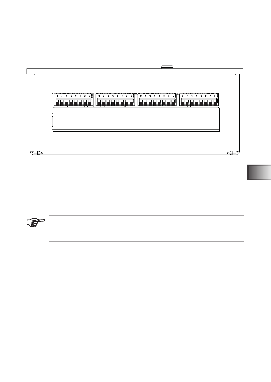
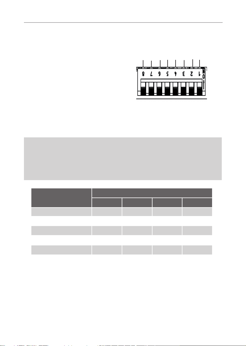
ON
OFF
DIP-Bank 4 DIP-Bank 3 DIP-Bank 2 DIP-Bank 1
6. Starting up
By default, all function selection switches are set to OFF.
Fig. 8: Function selection switch – Standard setting
Each DIP-Bank provides setting options for the product features of Infrabox
Basic, which are listed below and described in detail.
The settings made in each function setting are shown in the DIP-Bank as well
as the function selection switch.
EN
Note that the controller needs to be disconnected from the mains
for 10 seconds after making changes so that the settings are saved.
For standard deliveries, the features are as follows:
Operating mode: Normal
Operating type: Switch
Operating time: 6 hours
Foil sensor: Off
Leading/trailing edge phase control: Not activated
WORLD OF WELLNESSWORLD OF WELLNESS
Installation instructions, for professionals only p. 18/32
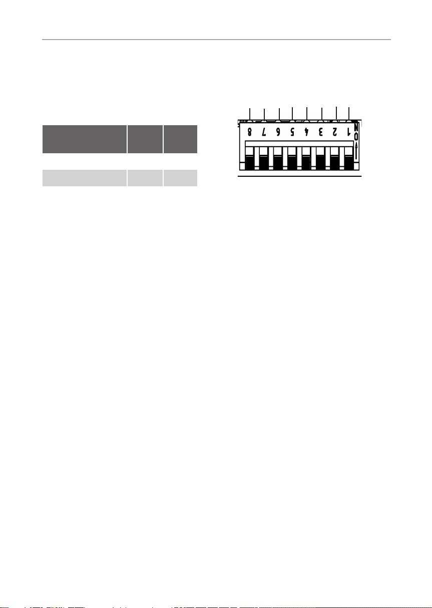
6.1. Operating mode
DIP-Bank 1
Function selection switch 1 and 2
In the operating mode the following
settings are possible:
Operating time
Operating time
Operating time
Operating time
Infra
Operating mode
Operating mode
Infra
Function selec-
tion switch
Normal OFF OFF
Timer I/0 ON OFF
1 2
ON
OFF
Fig. 9: Operating mode
Normal: Switchable or dimmable infrared heater/infrared plate.
The dimming function of the infrared heater/infrared plate is activated via the infracontroller, see 6.2. Operating type (infrared heater/infrared plate) on page 19.
Timer I/0 (On/Off): In the operating mode, On/Off switches the controls off after
the set On-time has elapsed and is not activated again.
Switchable infrared heater / infrared plate.
For additional settings, see 6.5. On-time (I/0 timer) on page 22 and Fig. 15:
Timer I/0 operating mode on page 23.

Installation instructions, for professionals only p. 19/32
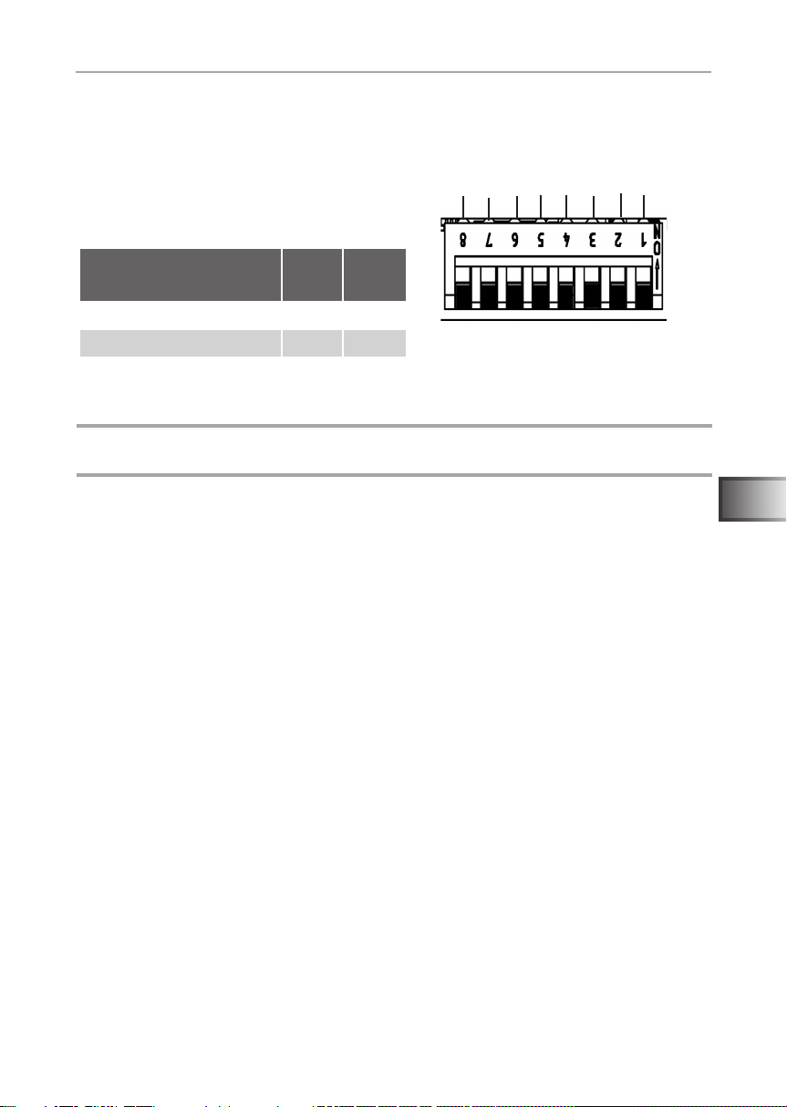
6.2. Operating type (infrared heater/
infrared plate)
DIP-Bank 1
Function selection switch 3 and 4
Operating mode
Infra
The following settings are possible
for the infra-controller:
Function selection
switch
Switch OFF OFF
Leading edge phase
control
Half-wave control OFF ON
ATTENTION!
The specied output limits may not be exceeded!
To enable optimum functionality, we recommend the leading edge phase control
function for infrared heaters with visible light. The half-wave control function is
suitable for infrared plates and infrared heaters without visible light.
3 4
ON OFF
Operating time
Fig. 10: Infrared operating type
Operating time
Operating time
Operating time
Operating mode
Infra
ON
OFF
EN
Switching: Switching the infrared heater or infrared plate with a heating capacity
of max. 3.5 kW. No dimming function.
Leading edge phase control: Controlling (dimming) the infrared heater/infrared
plate is possible in 5 levels up to 350 W.
Half-wave control: Controlling (dimming) the infrared heater/infrared plate is
possible in 5 levels up to 1.3 kW.
WORLD OF WELLNESSWORLD OF WELLNESS

Installation instructions, for professionals only p. 20/32
6.3. Operating time
DIP-Bank 1
Function selection switch 5 – 8
The maximum operating time is set to
6 hours as standard. The infrared controller shuts down automatically after the
maximum heating period for safety reasons.
The function selection switch in the lowvoltage connection area can be adjusted to
the maximum operating time. The required
positions of the function selection switch
can be found in the following table.
The EN 60335-2-53 species a maximum heating period limit of 6 hours
for private saunas. For saunas in hotels, apartment blocks and similar
locations, a maximum heating period limit of 12 hours is permissible.
Extending the heating period limit to 18 hours or 24 hours is only per-
!
mitted in public saunas.
Infra
Operating time
Fig. 11: Operating time
Operating time
Operating time
Operating time
Operating mode
Operating mode
Infra
ON
OFF
Time
5 min ON ON ON ON
10 min OFF ON ON ON
15 min ON OFF ON ON
30 min ON ON OFF ON
45 min OFF ON OFF ON
60 min ON OFF OFF ON
Function selection switch
5 6 7 8

Installation instructions, for professionals only p. 21/32
Time
Function selection switch
5 6 7 8
2 hours OFF OFF OFF ON
3 hours ON ON ON OFF
4 hours OFF ON ON OFF
5 hours ON OFF ON OFF
6 hours OFF OFF OFF OFF
12 hours ON OFF OFF OFF
18 hours OFF ON OFF OFF
24 hours ON ON OFF OFF
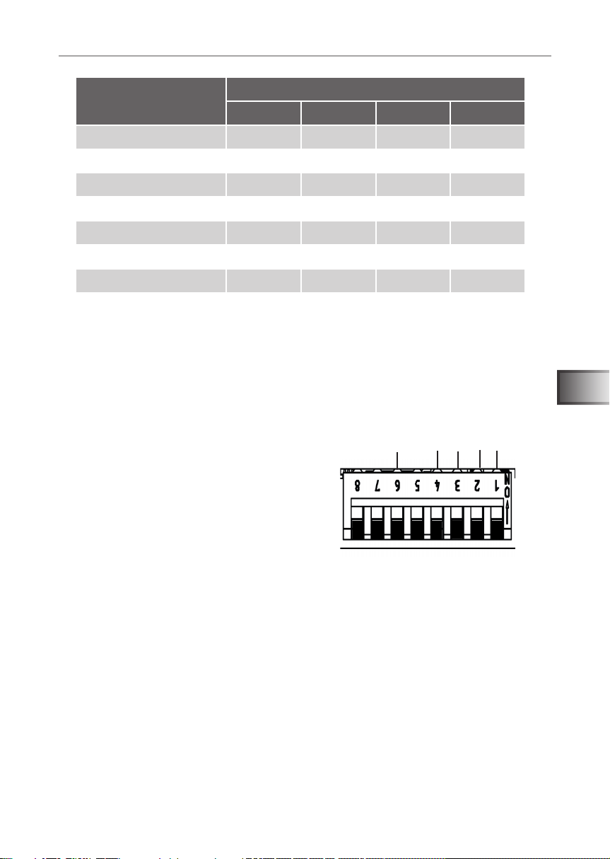
6.4. Foil sensor
DIP-Bank 4
Function selection switch 3
If an infrared plate is connected to the infrared output, the WC4-IRF-F foil sensor must
be used. The foil sensor must be activated
according to the adjacent gure by putting
switch 3 to ON.
Phase control
Remote start
leading/training edge
activation
Not assigned
Not assigned
Foil sensor
EN
ON
OFF
Fig. 12: Foil sensor
WORLD OF WELLNESSWORLD OF WELLNESS

Installation instructions, for professionals only p. 22/32
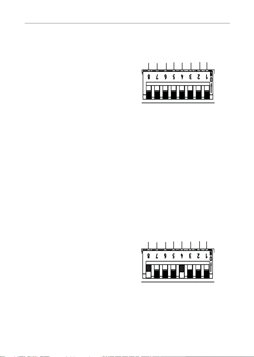
6.5. On-time (I/0 timer)
DIP-Bank 2
Function selection switch 3 – 6
Note: To activate the On-time, additional
settings are required, see 6.1. Operating
sec/min
x10
On-time
On-time
On-time
mode on page 18 and Fig. 15: Timer I/0
operating mode on page 23
Fig. 13:On-time
Function of the On-time: output begins to run or to clock after switching on the
controller according to the set times.
On-time: Setting the timer (timer function). Switching position of the required
value to ON according to the following table.
x10 – multiplicator (7): The timer set above the value is multiplied by 10.
OFF = deactivated, ON = activated
sec/min – unit (8): Switching from seconds to minutes.
OFF = seconds, ON = minutes
Seat-time
On-time
Seat-time
ON
OFF
Example: setting time 3 mins
x10
On-time
On-time
sec/min
Seat-time
On-time
On-time
Fig. 14: Example On-time
Seat-time
ON
OFF

Installation instructions, for professionals only p. 23/32
Time
Function selection switch
6 5 4 3
1 OFF OFF OFF OFF
2 OFF OFF OFF ON
3 OFF OFF ON OFF
4 OFF OFF ON ON
5 OFF ON OFF OFF
6 OFF ON OFF ON
7 OFF ON ON OFF
8 OFF ON ON ON
9 ON OFF OFF OFF
10 ON OFF OFF ON
11 ON OFF ON OFF
12 ON OFF ON ON
13 ON ON OFF OFF
14 ON ON OFF ON
15 ON ON ON OFF
16 ON ON ON ON
EN
Timer operating mode I/0 (On/Off): in the On/Off operating mode, the controller
switches off after the set On-time has elapsed and is not activated again.
Gesamtlaufzeit (siehe 6.3 Laufzeit)
EIN
Ein-Zeit
AUS
Fig. 15: Timer I/0 operating mode
WORLD OF WELLNESSWORLD OF WELLNESS
Installation instructions, for professionals only p. 24/32
6.6. Leading/trailing edge phase control
DIP-Bank 4
Function selection switch 4
Setting options:
Leading edge phase control: OFF (standard)
Trailing edge phase control: ON
For activating the leading/trailing edge
Remote start
leading/training edge
activation
Not assigned
Not assigned
Foil sensor
Phase control
phase control, additional settings are
required, see 6.1. Operating mode on page
18.
Function is available in Normal mode.
ON
OFF
Fig. 16: Leading/trailing edge
phase control
When the leading edge phase control mode is (see 6.2. Operating type (infrared
heater/infrared plate) on page 19) selected, there is the option of selecting
between leading/trailing edge phase control.
6.7. HV input (enable input)
DIP-Bank 4
Function selection switch 6
Enable input (ON position)
The controller can only be switched on if
230 VAC is applied at the HV input. This
function can be used with a vending machine for example.
See also 5.4. Connecting the HV input (enable input) on page 16.
Phase control
HV input
Fig. 17:HV input
Not assigned
Not assigned
Foil sensor
leading/training edge
ON
OFF

Installation instructions, for professionals only p. 25/32
7. Performing tests
The following tests must be performed by a certied electrical tter.
WARNING!
The following tests must be performed with the power supply
switched on. There is a danger of electric shock.
● NEVER touch live parts.
1. Check the contact of the earth conductors on the earth conductor terminal.
2. When using a foil sensor (see Fig. 6: Connection area for sensor/control
unit on page 14)
a. Unplug the sensor. Error code 3 (see 11.1. Error messages on page
30) is displayed.
b. When the correct code is displayed, plug the sensor in again.
3. When using a safety temperature limiter (seeFig. 6: Connection area for
sensor/control unit on page 14)
a. Unplug the safety temperature limiter. Error code 2 (see 11.1. Error
messages on page 30) is displayed.
b. When the correct code is displayed, plug the limiter in again.
4. When using infrared plates/infrared heaters (see Fig. 7: Connection area
for 230 V on page 15)
a. Check for functionality.
EN
WORLD OF WELLNESSWORLD OF WELLNESS

Instructions for use for the user p. 26/32
8. Safety information for the user
● The infrared controller must not be used by children under
8 years old.
● The infrared controller may be used by children age 8 years or
older, by persons with limited psychological, sensory or mental
capabilities or by persons with lack of experience/knowledge
only when:
– They are supervised.
– They have been shown how to use the device safely and
are aware of the hazards that could occur.
● Children must not play with the device.
● Children under 14 years old may only clean the device if they
are supervised.
● For health reasons, do not use the infrared cabin if you are under
the inuence of alcohol, medication or drugs.
● Before the infrared controller is switched on, make sure that no
ammable objects have been hung over the infrared heater or
on the infrared plate.
● For your own safety, consult your supplier in the event of prob-
lems that are not described in sufcient detail in the operating
instructions.

Instructions for use for the user p. 27/32
9. Operation
9.1. Description of control elements
1
2
5
3
4
1 Increase intensity/
Normal operating mode: On
2 Decrease intensity/
Normal operating mode: Off
3 ON/OFF button
WORLD OF WELLNESSWORLD OF WELLNESS
EN
4 Operating displays
5 Intensity displays/
On/Off display

Instructions for use for the user p. 28/32
WARNING!
Risk of re
● Before the infrared controller is switched on, make sure that no am-
mable objects have been hung over the infrared heater or on the
infrared plate.
9.2. Switching the infrared controller
1. Press the ON/OFF switch 3, to switch on the infrared controller.
► The operating display 4 goes on.
2. Select the intensity of the function with the intensity selector 1 and 2.
► The infrared heater/the infrared plate begins to heat up.
9.3. Dimming function for the infrared heater/infrared plate
Controlling (dimming) the infrared heater/infrared plate is possible in 5 levels.
At 0 the infrared heater/infrared plate is switched off, at 5 it is a full capacity.
Function only possible in operating modes: leading edge phase control and
half-wave control
To activate the function, additional settings are required, see chapter 6.2. Operating type (infrared heater/infrared plate) on page 19
Function only possible in operating mode: normal and seat
To activate the function, additional settings are required, see chapter 6.1. Operating mode on page 18
1. Use the intensity selector 1 and 2 to set the preferred infrared heater/
infrared plate intensity.
► The infrared heater/infrared plate is switched on.
► The intensity display 5 lights up.

Instructions for use for the user p. 29/32
10. Cleaning and maintenance
10.1. Cleaning
ATTENTION!
Damage to the unit
The Infrabox is protected against jets of water, however direct contact with water
could still damage the unit.
● Never immerse the device in water.
● Never pour water over the device.
● Never clean the device with a cloth which is too wet.
1. Immerse a cleaning cloth in a mild, soapy solution.
2. Wring the cleaning cloth out well.
3. Wipe the housing of the infrared controller carefully.
10.2. Maintenance
The infrared controller is maintenance-free.
EN
WORLD OF WELLNESSWORLD OF WELLNESS

Installation instructions, for professionals only p. 30/32
11. Troubleshooting
11.1. Error messages
The Infrabox Basic is equipped with diagnostic software which monitors system
statuses when it switches on and during operation. As soon as the diagnostic
software identies an error, the controller switches the infrared output off.
Errors are indicated by the LEDs ashing.
Switch the infrared controller off using the ON/OFF switch 3 (see 9.1. Description of control elements on page 27), unplug the cable from the mains and
rectify the error before switching the infrared controller on again.
The following table describes the possible errors and their causes. If necessary,
tell the number of the ashing LEDs to your customer service specialist.
Number
of LED
1 General information Please contact customer support.
2 Safety temperature limiter
breakage
3 Foil temperature sensor
is broken or short
circuited
4 Foil sensor
excess temperature
5 Communication error
between control unit
and power supply unit
Error Cause / rectication
Check the safety temperature
limiter or put a bridge in safety
temperature limiter terminal.
Defective temperature sensor
or poor contact or short circuit.
The maximum foil temperature
of 100 °C was exceeded. Sensor
must be activated via DIP.
Poor contact or defect connection
cable. Please contact customer
support.

Instructions for use for the user p. 31/32
12. Disposal
● Please dispose of packaging materials in accordance with the
applicable disposal regulations.
● Used devices contain reusable materials and hazardous substances.
Therefore, do not dispose of your used device with household waste,
but do so in accordance with the locally applicable regulations.
EN
WORLD OF WELLNESSWORLD OF WELLNESS

Instructions for installation and use p. 32/32
13. Technical data
Operating unit
Connection: 4-pin with power supply and communication lines
Mains voltage: 5 VDC
Output: <0.5 W
Storage temperature: -25 °C to 70 °C
Ambient temperature: -10 °C to +110 °C
Relative humidity: max. 99% rel. humidity,
non-condensing!
Dimensions: L x W x D 100.1 x 63.1 x 36.6 mm
Power supply unit
Nominal voltage 230 VAC
Dimensions 195 x 119 x 48 mm
Connection cable 3 x 1.5 mm² for light,
Contact rating / heater
Leading edge phase control 350 W
Half-wave control 1.3 kW
Switching 3.5 kW
Ambient conditions 10 °C to +40 °C
Electronics and heating elements
Light/fan power 100 W
Thermal safety
Adjustable automatic heating period (6 h, 12 h, 18 h, 24 h)*
* EN 60335-2-53 species a heating time limitation of 6 h for private saunas. For saunas in hotels,
apartment blocks and similar locations, a maximum heating period limit of 12 hours is permissible.
Extending the heating period limit to 18 hours or 24 hours is only permitted in public saunas.
WORLD OF WELLNESS

NOTIZEN / APPUNTI / NOTES / NOTE / NOTITIES
………………………………………………….............………………………………………………………………...
…………………………………………………………….......……………………………………………………………...
…………………………………………………………….............………………………………………………………...
…………………………………………………….............………………………………………………………………...
……………………………………………………………......……………………………………………………………...
……………………………………………………………......……………………………………………………………...
……………………………………………………………..........…………………………………………………………...
…………………………………………………………….............………………………………………………………...
…………………………………………………………….............………………………………………………………...
…………………………………………………………….............………………………………………………………...
…………………………………………………………….............………………………………………………………...
…………………………………………………………….............………………………………………………………...
.…………………………………………………………….............………………………………………………………...
…………………………………………………………….............………………………………………………………...
…………………………………………………………….............………………………………………………………...
…………………………………………………………….............………………………………………………………...
…………………………………………………………….............………………………………………………………...
…………………………………………………………….............………………………………………………………...
…………………………………………………………….............………………………………………………………...
WORLD OF WELLNESSWORLD OF WELLNESS

sentiotec GmbH world of wellness Oberregauer Straße 48 4844 Regau, Austria
T +43 (0) 7672/277 20-567 F +43 (0) 7672/277 20-801
E info@sentiotec.com www.sentiotec.com
 Loading...