

Sentiotec wave.com4 touch II, WC4-B-TC2, WC4-B-L+, WC4-H-PCB+, WC4-H-F2 Instructions For Installation And Use Manual
...
wave.com4 touch II
ALL-IN-ONE BEDIENTEIL
WC4-B-TC2
MONTAGE- UND GEBRAUCHSANWEISUNG
Deutsch
All-in-One Bedienteil, das mit selbstbewusstem Design punktet.
Version 11/13 Ident-Nr. 1-026-981
DE
EN
FR
IT
NL
SV
CS
FI

Inhaltsverzeichnis
1 Allgemeine Sicherheitshinweisel 3
2 Bestimmungsgemäßer Gebrauch 4
3 Allgemeine Funktionsbeschreibung 4
3.1 Tabelle verfügbare Funktionen 4
4 Reinigung des Bedienteils 5
5 Montage des Bedienteils 6
6 Elektrischer Anschluss nur für Fachpersonal 7
6.1 Rückansicht wave.com4 touch 7
6.2 Anschluss Lautsprecher und Klemmenbelegung 7
6.3 Blockschaltbilder 8
7 KongurationderLeistungsteilefürdenAnschlussandiewave.com4 touch 9
7.1 Wave.com4 Sauna Basismodul WC4-B-L 9
7.2 Sound & Light WC4-SL-L 9
7.3 wave.com4 Infra WC4-IRX-P 9
7.3 Einbindung herkömmlicher Bedienteile 10
8 Inbetriebnahme – nur für Fachpersonal 11
9 Technikereinstellungen – nur für Fachpersonal 11
9.1 Einstellungen im Technikermenü vornehmen 11
10 Beschreibung der Optionen im Technikermenü 12
10.1 Option wave.com4 Saunasteuerung 12
10.2 Option wave.com4 Saunasteuerung- Fernkontakt 12
10.3 Option Infrarot 12
10.4 Option wave.com4 Infra- Fernstart 12
10.5 Option Kabinenlicht 13
10.6 Option Max. Laufzeit: 13
10.7 Werkeinstellungen: 13
10.8 Option Audio Quelle 13
10.9 Option Audio Shufe 13
11 Softwareupdate – nur für Fachpersonal 14
12 Bedien- und Anzeigeelemente 15
12.1 Menü 16
13 Einschalten 16
14 Allgemeine Benutzerführung 17
14.1 Saunatemperatur einstellen 17
14.2 Feuchte einstellen 17
14.3 Infraroteinstellungen 17
14.4 Tageslicht einstellen (Kabinenlicht) 18
14.5 Farblicht einstellen 18
14.6 Lüfter 18
14.7 Musik 18
15 Musik Shortkeys 18
16 Programme einstellen 19
16.1 Infrarot: 19
16.2 Farblicht: 19
17 AllgemeineEinstellungen/Kongurationen 19
17.1 Allgemein 19
17.2 Techniker 19
17.3 Datum/Uhr einstellen
17.4 Displayhelligkeit einstellen 20
17.5 Menü Sprache 20
17.6 Feedback 20
17.7 Auto-Hauptfenster-Zeit 20
18 Vorwahlzeit einstellen 20
19 Technische Daten 21
20 Garantiebestimmungen 22
21 Entsorgung 22
22 Lieferumfang 22
Montage- und Gebrauchsanweisung S. 2/22

1 Allgemeine Sicherheitshinweise
Bedeutung der in der Bedienungs- und Montageanweisung verwendeten Symbole:
WARNUNG:
Bei Nichtbeachtung besteht die Möglichkeit einer schweren oder sogar tödlichen Verletzung.
VORSICHT:
Bei Nichtbeachtung besteht die Möglichkeit von mittleren bis leichten Verletzungen oder Sachschäden.
HINWEIS:
Gibt Anwendungstipps und nützliche Informationen.
Bewahren Sie diese Montage- und Gebrauchsanweisung sorgfältig in der Nähe des Bedienteils auf, um
jederzeit Sicherheitshinweise und Informationen zur Bedienung nachschlagen zu können.
• Unsachgemäße Montage kann zu Brandgefahr führen!
• Der elektrische Anschluss darf ausschließlich von qualiziertem Fachpersonal durchgeführt werden.
• Der Anschluss muss nach Anschlussschema erfolgen.
• Bevor das Bedienteil in Betrieb genommen wird, muss überprüft werden, ob alle Verbindungen lösungssi-
cher verbunden sind.
• Dieses Gerät ist nicht dafür bestimmt, durch Personen (einschließlich Kinder) mit eingeschränkten physischen, sensorischen oder geistigen Fähigkeiten oder mangels Erfahrung und/oder mangels Wissen benutzt
zu werden, es sei denn, sie werden durch eine für ihre Sicherheit zuständige Person beaufsichtigt.
• Kinder sollten beaufsichtigt werden, um sicherzustellen, dass sie nicht mit dem Gerät spielen.
• Das Gerät ist nicht geeignet Saunaheizgeräte direkt zu steuern! Brandgefahr!
• Bewahren Sie diese Montage- und Gebrauchsanweisung sorgfältig in der Nähe der Steuerung auf, um je-
derzeit Sicherheitshinweise und wichtige Informationen zur Bedienung nachschlagen zu können.
• Beachten Sie auch die speziellen Sicherheitshinweise der einzelnen Kapitel.
• Beim Auftreten besonderer Probleme, die in dieser Gebrauchsanweisung nicht ausführlich genug behandelt
werden, wenden Sie sich zu Ihrer eigenen Sicherheit an Ihren Lieferanten.
• Eigenmächtige Änderungen oder Umbauten an der Saunasteuerung sind aus Sicherheitsgründen nicht gestattet.
• Lesen Sie diese Montage- und Gebrauchsanleitung sorgfältig vor der Montage des Geräts durch. Dadurch
nutzen Sie alle Vorteile, die das Gerät bietet und beugen Schäden vor.
• Auf Grund der hohen Temperaturen und Kondenswasser in der Saunakabine ist das wave.com4 touch Bedienteil nicht für den Einbau in der Saunakabine geeignet.
• Es sind die Bedienungsanleitungen der kombinierbaren Geräte der wave.com4 Serie zu befolgen und sind
Teil dieser Gebrauchsanweisung.
• Das wave.com4 touch Bedienteil darf nur unter genauer Einhaltung dieser Anleitung angeschlossen werden! Verwenden Sie ausnahmslos die mitgelieferten Originalkabel und Originalteile. Nur bei Verwendung
dieser Kabel sind die Normen (Leitungsquerschnitt, Isolierung, Temperaturklasse, usw.) sicher eingehalten.
• Technische Änderungen vorbehalten.
Montage- und Gebrauchsanweisung S. 3/22
WORLD OF WELLNESSWORLD OF WELLNESS
DE

2 Bestimmungsgemäßer Gebrauch
Das wave.com4 touch Bedienteil dient ausschließlich dem Bedienen von Geräten der wave.com4 Serie. Gemäß dieser Bestimmung kann das wave.com4 touch Bedienteil in seiner vollen Funktion genutzt werden.
Weiters gelten die Sicherheits- und Gebrauchshinweise der jeweilig angeschlossenen Geräte.
3 Allgemeine Funktionsbeschreibung
Das wave.com4 touch Bedienteil verfügt über eine automatische Erkennung der angeschlossenen Geräte.Je nach erkannten Geräten erscheinen die jeweiligen Menüpunkte.
An- und Abstecken von Geräten nur im spannungsfreien Zustand durchführen.
Je nach angeschlossenen Geräten stehen folgende Betriebsarten und Funktionen zur Verfügung. Siehe auch
Tabelle der verfügbaren Funktionen:
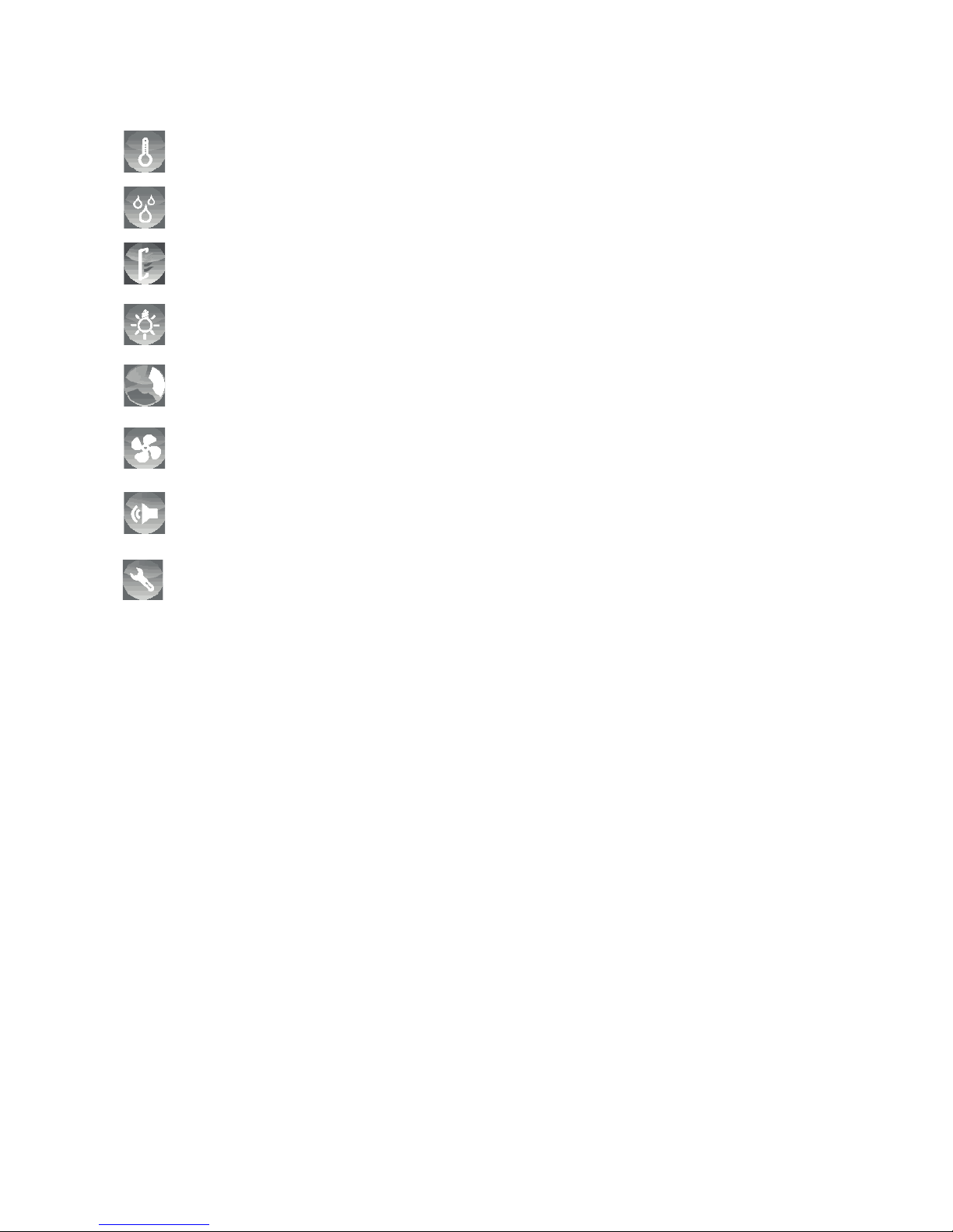
• Finnischer Betrieb
• Klimabetrieb
• Infrarotbetrieb
• Sound- und Lichteffekte
• Lüfter
• Kabinenlicht
• Programme
Die Versorgung kann über eines oder mehrere unten genannter Geräte erfolgen:
• wave.com4 Basismodul (Finnische Sauna)
• wave.com4 Basismodul mit Erweiterungsmodul (Kombi Sauna)
• wave.com4 Infra
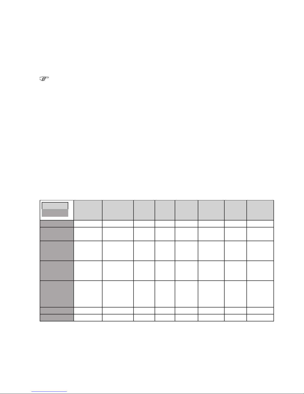
3.1 Tabelle verfügbare Funktionen:
Funktion
Gerät
Finnischer
Betrieb
Klima/Combibetrieb
Farblicht Sound Kabinen-
licht
3
Infrarotbetrieb
Lüfter 42-Fühler
Regelung
WC4-B-L JA JA
1
JA
WC4-B-L +
WC4-H-PCB + JA JA
1
JA JA
WC4-B-L +
WC4-H-PCB +
WC4-H-F2
JA JA
1
JA JA JA
5
WC4-B-L +
WC4-H-PCB +
WC4-H-H
JA JA JA
1
JA JA
WC4-B-L +
WC4-H-PCB +
WC4-H-F2 +
WC4-H-H
JA JA JA
1
JA JA JA
5
WC4-IRX-P JA
1
JA JA JA
WC4-SL-L JA JA
2
1
Externe Lautsprecher 8Ohm notwendig – nicht im Lieferumfang enthalten
2
Die Farblampe wird als Lautsprecher verwendet. Siehe auch Anschluss sound&light - nur für Fachpersonal.
3
Bei Kombination von WC4-IRX-P und WC4-B-L kann in den Systemparametern ausgewählt werden welches
Gerät das Kabinenlicht steuert.
4
Bei Kombination von WC4-IRX-P und WC4-B-L kann in den Systemparametern ausgewählt werden welches
Gerät den Lüfter steuert.
5
Der Bankfühler muss in den Systemparametern aktiviert werden.
Montage- und Gebrauchsanweisung S. 4/22
WC4-B-L: wave.com4 Basismodul Leistungsmodul
WC4-H-PCB: wave.com4 Erweiterungsplatine
WC4-H-H: wave.com4 Feuchtefühler
WC4-H-F2: wave.com4 Bankfühler
WC4-IRX-P: wave.com4 Infra Leistungsteil
WC4-SL-L: wave.com4 sound&light Farblampe
Wird WC4-B-L mit WC4-SL-L kombiniert wird zusätzlich das Kabelset WC4-SL-EXT benötigt. Siehe auch
„Elektrischer Anschluss - nur für Fachpersonal“.
wave.com4 Sauna Basismodule (WC4-B-L) vor Produktionsdatum 12/2011 sind nicht mit dem wave.com
touch Bedienteil kompatibel. Das notwendige Software Update kann nur im Werk durchgeführt werden.
4 Reinigung des Bedienteils
Reinigen Sie das Bedienteil je nach Verschmutzung.
Trennen Sie die komplette Steuerung vom Netz.
Mit einem mit neutralem Seifenwasser leicht angefeuchteten weichen Tuch (z. B. Mikrofasertuch) die Front des
Bedienteils sanft abwischen.
Die Rückseite und die dahinterliegende Platine keinesfalls selbst reinigen, das Gerät kann dabei Schaden
nehmen! Gegebenfalls Servicepersonal anfordern.
Auf Grund der hohen Temperaturen und Kondenswasser in der Saunakabine ist das wave.com4 touch Be-
dienteil nicht für den Einbau in der Saunakabine geeignet.
Montage- und Gebrauchsanweisung S. 5/22
WORLD OF WELLNESSWORLD OF WELLNESS
DE

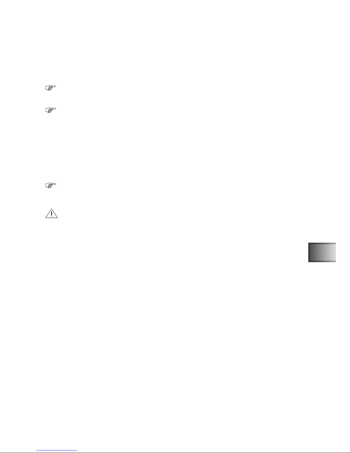
5 Montage des Bedienteils
Für die Montage des wave.com4 touch Bedienteils ist ein Ausschnitt von 213 mm x 82 mm vorzusehen, in die
der Montagerahmen B eingesetzt wird. Zum Fixieren des Rahmens die Laschen C wie in der Abbildung mit einem Schraubendreher biegen. Die Einbautiefe des wave.com4 touch Bedienteils beträgt 36 mm.
Nach der Verkabelung (siehe Abschnitt Verkabelung) das Bedienteil A wie in der Abbildung in den Rahmen B einsetzen
Montage Einbaurahmen
Einsetzen des Bedienteils in den Montagerahmen
Abmessungen
Montageanweisung nur für Fachpersonal S. 6/22

6 Elektrischer Anschluss nur für Fachpersonal
Beachten Sie auch die Anweisungen in den Bedienungs- und Montageanleitungen der verwendeten Leistungsteile.
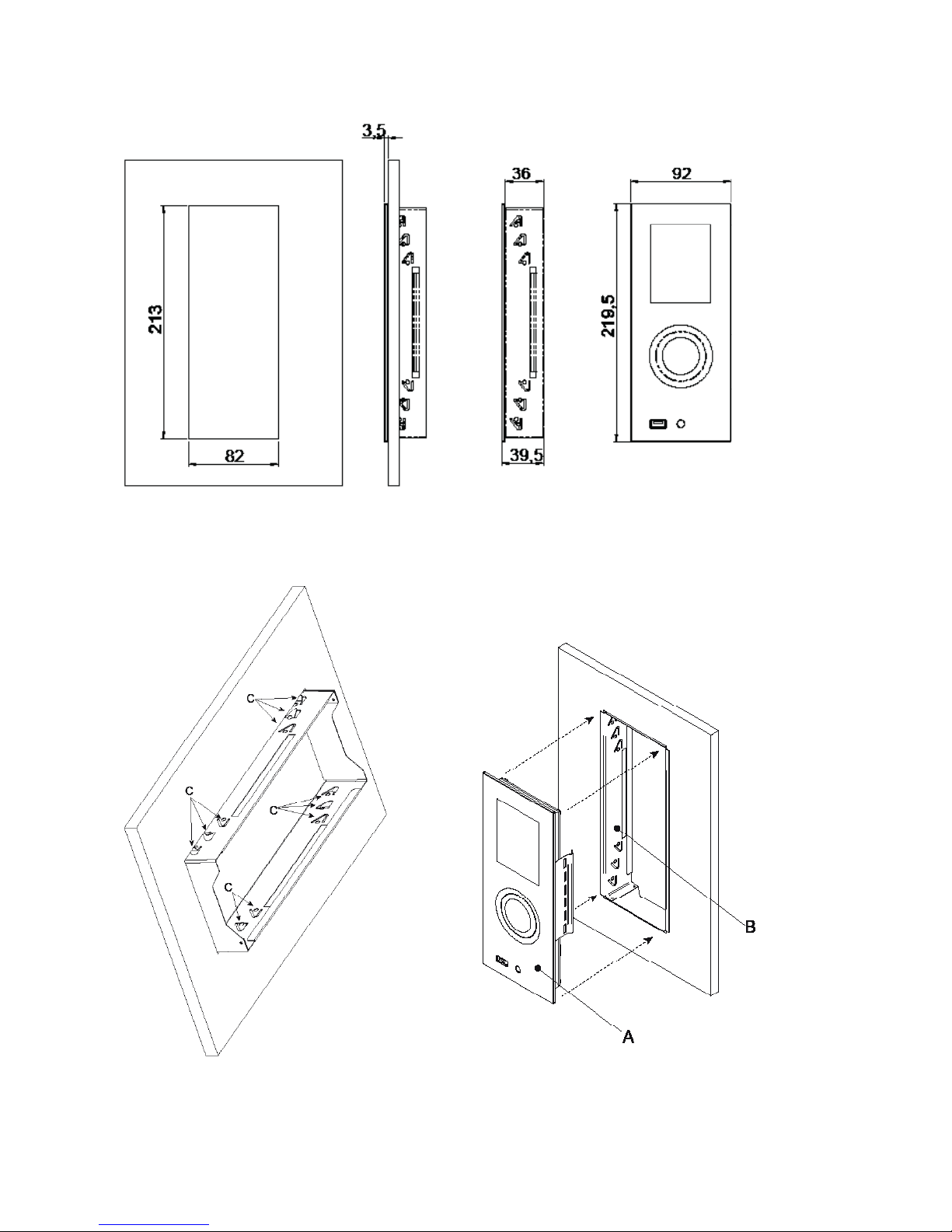
6.1 Rückansicht wave.com4 touch
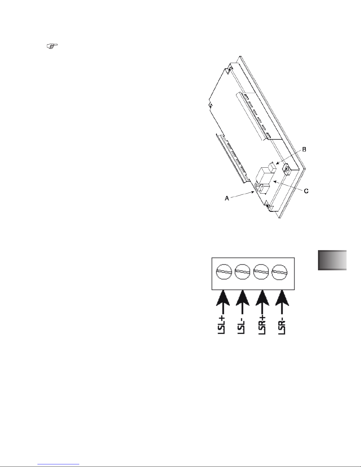
6.2 Anschluss Lautsprecher und Klemmenbelegung
LSL+ Lautsprecher links +
LSL- Lautsprecher links –
LSR+ Lautsprecher rechts +
LSR- Lautsprecher rechts –
Bei Verwendung der sound & light mit dem wave.com4 touch
können die Lautsprecher an das wave.com4 touch (Klemmblock C) angeschlossen werden.
Eine Nutzung des in der sound & light integrierten MP3 Players (Anschluss der Lautsprecher der Farblampe am
Leistungsteil der S&L gemäß der Bedienungsanleitung S&L) und des Verstärkers ist möglich (auswählbar im
Systemmenü).
LSL+ Lautsprecher links + Braun
LSL- Lautsprecher links – Blau
LSR+ Lautsprecher rechts + Grau
LSR- Lautsprecher rechts – Schwarz
Der Schalter B ist derzeit nicht in Verwendung und für spätere Anwendungen reserviert.
Ansicht hinten
Klemmblock C
Die einzelnen Module werden über 6-polige RJ12 Kabel miteinander verbunden.
Beim Bedienteil wird das Buskabel in die Buchse A gesteckt.
Siehe auch Blockschaltbilder.
Die Lautsprecher werden über den Klemmenblock C angeschlossen.
Montageanweisung nur für Fachpersonal S. 7/22
DE
WORLD OF WELLNESSWORLD OF WELLNESS
6.3 Blockschaltbilder
wave.com4 Sauna Basismodule (WC4-B-L) vor Produktionsdatum 12/2011 sind nicht mit dem wave.com4
touch Bedienteil kompatibel. Das notwendige Software Update kann nur im Werk durchgeführt werden.
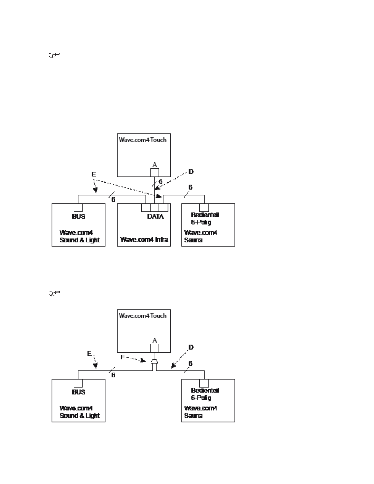
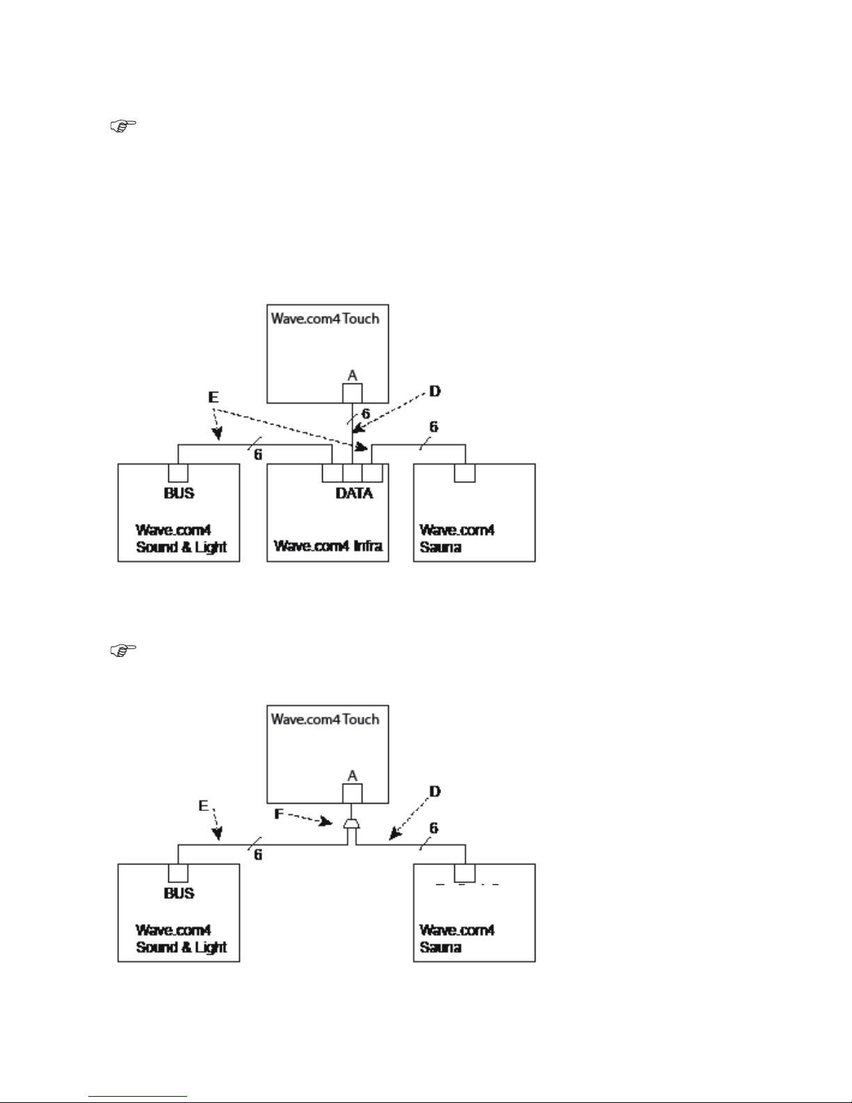
Die Verbindung der einzelnen Geräte erfolgt über 6-polige RJ12 Kabel (D und E). Ein Verbindungskabel D ist
im Lieferumfang des wave.com4 touch Bedienteils enthalten. Für den Anschluss von mehreren Leistungsteilen
muss für jedes Leistungsteil ein Verbindungskabel O-CX-C10 (E) bestellt werden.
Wenn nur die wave.com4 sound & light und das wave.com4 Sauna Basismodul verwendet werden, wird zusätzlich ein Y-Verbinder F benötigt. Dieser ist im WC4-SL-EXT enthalten.
Im Set WC4-SL-EXT ist auch das Datenkabel E enthalten
Blockschaltbild Vollausbau
Blockschaltbild sound & light mit wave.com4 Sauna
Montageanweisung nur für Fachpersonal S. 8/22
7 KongurationderLeistungsteilefürdenAnschlussandiewave.
com4 touch
7.1 wave.com4 Sauna Basismodul WC4-B-L
wave.com4 Sauna Basismodule (WC4-B-L) vor Produktionsdatum 12/2011 sind nicht mit dem wave.com4
touch Bedienteil kompatibel. Das notwendige Software Update kann nur im Werk druchgeführt werden.
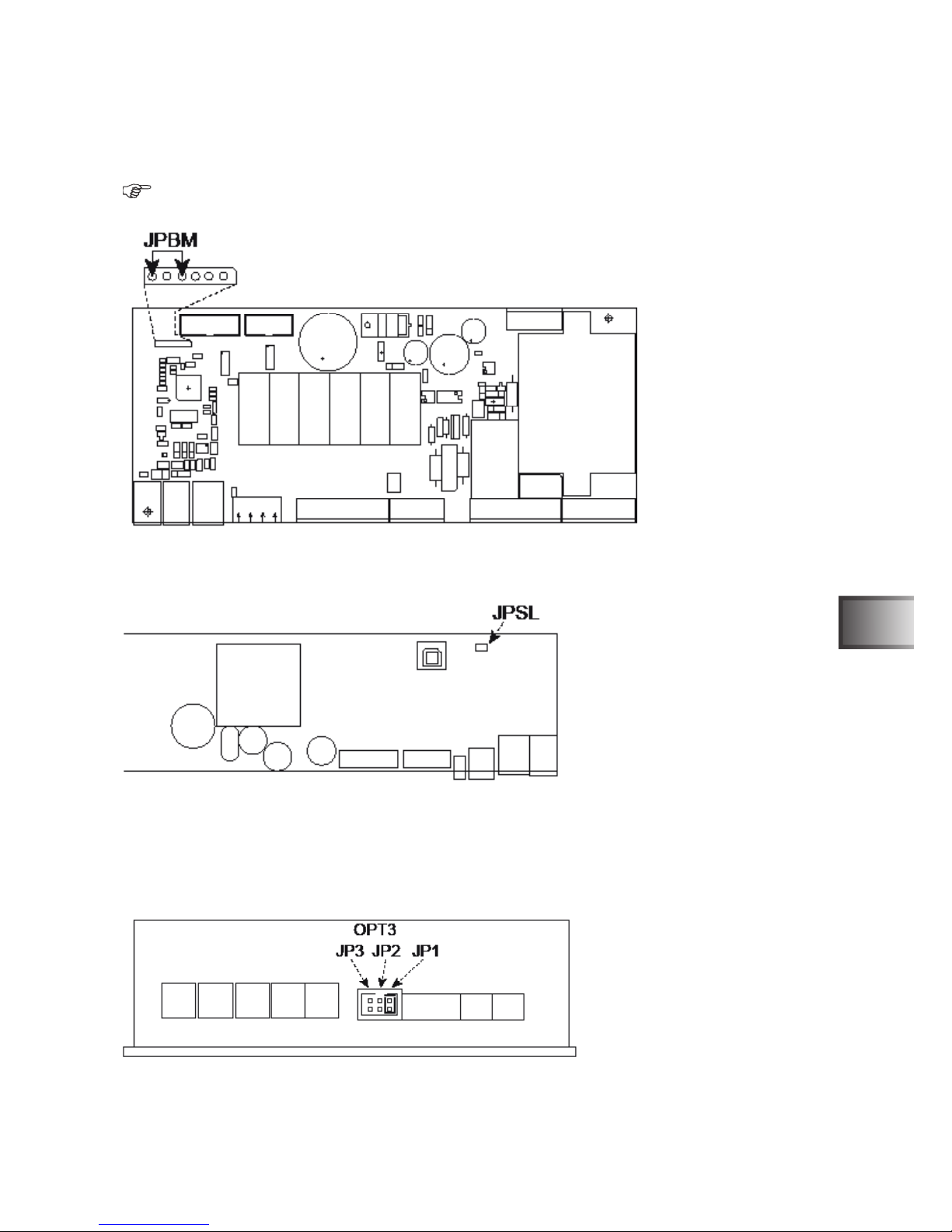
Der Jumper JPBM ist im Lieferumfang der wave.com4 touch enthalten. Diesen - wie in der Abbildung gezeigt in die 6-polige Buchsenleiste einsetzen.
7.2 Sound & Light WC4-SL-L
Der werksseitig gesetzte Jumper JPSL muss in seiner Position verbleiben.
Wenn mehrere sound & light (bis zu vier Geräte möglich) verwendet werden, muss abweichend zu den Anweisungen in der Bedienungs- und Montageanleitung, der Jumper JPSL bei allen am Bus angeschlossenen Geräten in seiner Position verbleiben.
7.3 wave.com4 Infra WC4-IRX-P
Den der wave.com4 touch beiliegenden Jumper bei Stiftwanne OPT3 auf JP1 setzen. Bei Verwendung von
mehreren (bis zu vier Geräte möglich) wave.com4 Infra Leistungsteilen, entnehmen Sie die Konguration der
Bedienungs- und Montageanleitung der wave.com4 Infra.
Jumper Basismodul
Jumper SL
Jumper Infra
Montageanweisung nur für Fachpersonal S. 9/22
DE
WORLD OF WELLNESSWORLD OF WELLNESS

7.3 Einbindung herkömmlicher Bedienteile
Mit V.1.04 ist es möglich, die herkömmlichen Bedienteile in Ihr Saunasystem zu integrieren. Diese zeigen dann
die von Ihnen gewählte Betriebsart an. Sie können am Bedienteil Einstellungen vornehmen bzw. ändern- die
Bedienteile kommunizieren mit Ihrem wave.com4 touch Bedienteil.
Verwendbare Bedienteile:
WC4-B-S/W/D/H WC4-IRX-S/W/D/H WC4-SL-S/W/H/D
Zur Verwendung dieser Funktion mit dem Bedienteil WC4-SL-S/W/H/D, vor Produktionsdatum 11/2012 be-
darf es möglicherweise eines Softwareupdates Ihres Bedienteils! Hierfür ist eine Einsendung des Bedien-
teils WC4-SL-S/W/H/D erforderlich!
Vor Anbindung des Bedienteils WC4-SL-S/W/D/H muss das Bedienteil zuvor auf BUS-Konguration kon-
guriert werden. Gehen Sie hier folgendermaßen vor:
* Bedienteil vom Leistungsteil abstecken (RJ10 4/4).
* +/- Tasten gleichzeitig gedrückt halten und RJ10 4/4 Datenleitung wieder anstecken.
* mit den +/- Tasten „TC4“ auswählen.
* Die Auswahl mit der Mode-Taste bestätigen.
* mit den +/- Tasten „Po0“ auswählen.
* Die Auswahl mit der Mode-Taste bestätigen.
Die herkömmlichen Bedienteile WC4-B-S/W/D/H, WC4-IRX-S/W/D/H, WC4-SL-S/W/H/D können innerhalb
Ihrer Saunakabine montiert werden! Beachten Sie hierfür die Anmerkungen in der jeweiligen Bedienungs-
anleitung. Die Umgebungsparameter (siehe Technische Daten der jeweiligen Bedienungsanleitung) müs-
sen unbedingt eingehalten werden!
Bei Verwendung von 2 Bedienteilen am Bus (möglich bei Wave.com4 und Wave.com4 Infra- RJ10 4/4 An-
schluss und auch S&L) ist zu beachten, dass jedem einzelnen Bedienteil eine jeweils andere Busadresse
zugewiesen wird- Beachten Sie hierfür weiterführende Bemerkungen in den jeweiligen Bedienungsanleitun-
gen (Wave.com4 und Wave.com4 Infra)
Montageanweisung nur für Fachpersonal S. 10/22
8 Inbetriebnahme – nur für Fachpersonal
Überprüfen Sie den korrekten Anschluss aller verwendeten Module.
Überprüfen Sie, ob alle Jumper auf den einzelnen Geräten korrekt gesetzt sind. Änderungen der Jumper
bei angelegter Netzspannung werden nicht erkannt.
Nach Anlegen der Netzspannung werden die einzelnen Module vom wave.com4 touch Bedienteil automatisch
erkannt.
Die erkannten Module werden im Display durch ihre jeweiligen Menüpunkte angezeigt. Siehe Technikereinstellungen und Bedienungsanleitung für den Benutzer
9 Technikereinstellungen – nur für Fachpersonal
In den Technikereinstellungen wird die abschließende Konguration des Gesamtsystems vorgenommen.
Die verfügbaren Optionen werden durch die angeschlossenen Module vorgegeben.
Beachten Sie den Abschnitt Bedienungsanleitung für Benutzer (Anzeige- und Bedienelemente)
9.1 Einstellungen im Technikermenü vornehmen
1
2
3
4
5
67
8
9
10
11
Frontglas Bedien und Anzeigeelemente
Durch Longpress auf OK 1 wird die Steuerung
aktiviert und der Homescreen mit den verfügbaren
Einstellmöglichkeiten wird angezeigt.
Das Technikermenü wird durch Longpress auf die
C-Taste 2 aktiviert. Navigieren Sie mit dem Touch
Wheel 4 auf den Menüpunkt „Techniker“.
Bestätigen Sie mit der OK-Taste 3.
Hier können nun die Einstellungen der Module vorgenommen werden.
Zum Auswählen eines Menüpunktes navigieren Sie
mit dem Touch Wheel 4 auf die zu ändernde Option und wählen Sie diese mit OK 3 aus.
Um eine Ebene zurückzuspringen drücken Sie C 2.
Montageanweisung nur für Fachpersonal S. 11/22
DE
WORLD OF WELLNESSWORLD OF WELLNESS

10 Beschreibung der Optionen im Technikermenü
Je nachdem welche Module bzw. Leistungsteile angeschlossen sind werden die jeweiligen Menüpunkte
ein- oder ausgeblendet.
Je nachdem welche Einstellungen im Technikermenü vorgenommen werden, werden einzelne Menüpunkte ein- oder ausgeblendet.
Werkseinstellungen sind fett geschrieben
10.1 Option wave.com4 Saunasteuerung
• Verdampfer Aus/Ein Deaktiviert bei angeschlossener Erweiterungsplatine (WC4-H-PCB)
den Verdampferausgang und blendet den Menüpunkt „Feuchte“ im
Homescreen aus.
• Lüfter Aus/Ein Aktiviert den Lüfterausgang am wave.com4 Saunasteuerung Basis-
modul. Der Lüfterausgang der wave.com4 Infra wird dann automatisch
deaktiviert
• Bankfühler Aus/Ein
• Funktion Res5 Wm (Wassermangelfunktion Verdampfer)/Fs (Fernstart). Aktiviert den
Fernstart am wave.com4 Saunasteuerung Basismodul. Die Wasser mangelerkennung ist danach nicht mehr verfügbar. Der Fernstartein-
gang der wave.com4 Infra wird dann automatisch deaktiviert
Beachten Sie auch die Hinweise in der Bedienungs- und Montageanleitung der wave.com4 Saunasteuerung
10.2 Option wave.com4 Saunasteuerung- Fernkontakt
Hier können Sie der Steuerung vorgeben, ob die Wave.com4 Saunasteuerung nach Wegfall der Fernkontaktspannung eingeschalten bleiben soll:
Einschalten (Auswahl = „Ein“)
Ausschalten (Auswahl “Aus“)
10.3 Option Infrarot
Lüfter Aus/Ein Aktiviert den Lüfterausgang am wave.com4 Infra. Der Lüfterausgang
der wave.com4 Saunasteuerung Basismodul wird dann automatisch
deaktiviert.
Schaltausgang 1 Aus/Ein Aktiviert den Potentialfreien OPT1 Ausgang. Dieser schaltet sich beim
Wechseln in den Standbymodus automatisch ab.
Schaltausgang 2 Aus/Ein Aktiviert den Potentialfreien OPT2 Ausgang. Dieser schaltet sich beim
Wechseln in den Standbymodus automatisch ab.
Fernstart Aus/Ein; Aktiviert den Fernstarteingang an der wave.com4 Infra. Der Fernstart-
eingang der wave.com4 Saunasteuerung Basismodul wird dann auto-
matisch deaktiviert. Beachten Sie die Anweisung in der Bedienungs-
und Montageanleitung der wave.com4 Infra.
10.4 Option wave.com4 Infra- Fernstart
Hier können Sie der Steuerung vorgeben, ob die Wave.com4 Infra (Infrarotsteuerung) auf Fernstart reagieren
soll oder nicht. Der Fernstart bei der Wave.com4 Infra Infrarotsteuerung erfolgt mittels Schalter.
Entnehmen Sie weitere Informationen, den Fernstart Wave.com4 Infra betreffend, der Bedienungsanlei-
tung der Wave.com4 Infra.
Montageanweisung nur für Fachpersonal S. 12/22

Diese Funktion kann nur durch ein Update des Leistungsteils WC4-IRX-P genutzt werden! Hierfür ist eine
Einsendung des Leistungsteils WC4-IRX-P erforderlich!
10.5 Option Kabinenlicht
Hier können Sie wählen, über welches Modul (wave.com4 Basis mit/ohne Feuchtemodul oder wave.com4 Infra)
Sie das Kabinenlicht beziehen.
o SAN (wave.com4 Basis (oder Basis mit Feuchteerweiterung))
o INF (wave.com4 Infra)
10.6 Option Max. Laufzeit:
Hier können Sie die maximale Laufzeit ändern.
o 6h (lt. Norm EN 60335-2-53 und EN 60335-1 maximale Betriebsdauer im privaten Bereich)
o 12h (lt. Norm EN 60335-2-53 und EN 60335-1 maximale Betriebsdauer im gewerblichen Bereich)
10.7 Werkeinstellungen:
Longpress auf OK 3
Hier können Sie das wave.com4 touch Bedienteil auf seinen softwaretechnischen Auslieferungsstand zurückführen. Schalten Sie nach Bestätigen dieser Option das Gerät aus und dann wieder ein.
10.8 Option Audio Quelle
Hier können Sie wählen, welche USB- Audioquelle Sie verwenden möchten:
Sound&Light (optionales WC4-SL-L erforderlich) als Audio-Quelle wählen
wave.com4 touch Bedienteilteil als Audio-Quelle wählen
Eine Mehrfachselektion ist nicht möglich! Das Anwählen einer Audioquelle deaktiviert jeweils die andere
Audio-Quelle.
10.9OptionAudioShufe
Bei Wählen dieser Option wird die Zufallswiedergabe (Audio) aktiviert. Es werden somit alle MP3-Files, die sich
auf Ihrem USB-Stick benden, zufällig wiedergegeben.
Hier wird eine Ordnerstruktur, die auf Ihrem USB-Stick möglicherweise besteht, nicht berücksichtigt, d. h.
es wird nicht zufällig ein kompletter Ordner abgespielt.
Montageanweisung nur für Fachpersonal S. 13/22
DE
WORLD OF WELLNESSWORLD OF WELLNESS

11 Softwareupdate – nur für Fachpersonal
Notieren Sie sich die Konguration. Durch das Softwareupdate werden die Einstellungen zurückgesetzt
Die notwendigen Daten und Programmdateien werden auf Anforderung zur Verfügung gestellt.
Um das Update durchzuführen gehen Sie wie folgt vor:
-> Schalten Sie das Gerät ein.
-> Stecken Sie den USB-Stick mit den Update Daten in den USB-Port der wave.com4 touch
EsdürfensichaußerdemUpdatekeineweiterenDatenaufdemUSB-Stickbenden
-> Navigieren Sie im Technikermenü auf den Menüpunkt Werkseinstellungen.
-> Durch Longpress auf C 2 starten Sie das Softwareupdate
-> Warten Sie bis das Update abgeschlossen ist. Trennen Sie das Gerät während des Softwareupdates keinesfalls vom Netz.
-> Nach dem Update geht das wave.com4 touch in den Standby-Zustand.
Die Aktualisierung der Software kann durch Ihren Saunahändler via USB-Port des Touch durchgeführt
werden. Bitte informieren Sie sich über erhältliche Softwareupdates.
Ein geeigneter USB-Stick für das wave.com4 touch Bedienteil ist optional erhältlich (WC4-USB-M):
Montageanweisung nur für Fachpersonal S. 14/22
WORLD OF WELLNESS
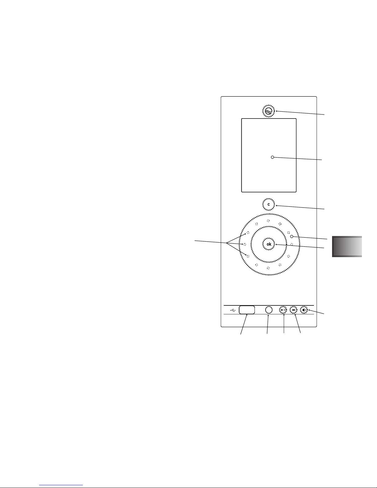
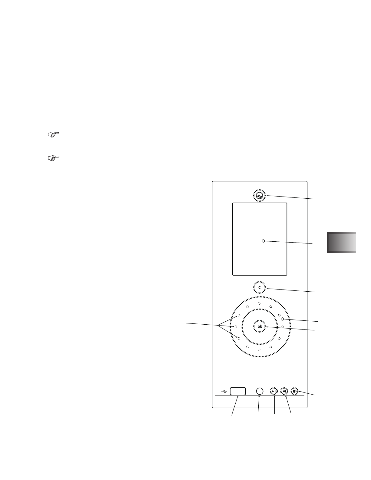
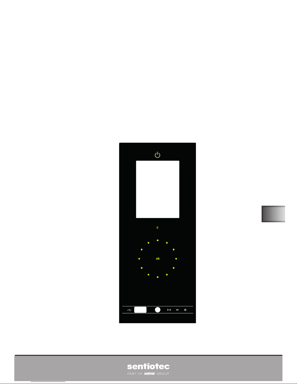
12 Bedien- und Anzeigeelemente
1 Taste Ein/Aus
Wenn die Taste weiß leuchtet, bendet sich
das System im Standby-Modus.
2 Taste c
3 Taste OK
4 Touch-Wheel Rad (Navigationsrad)
5 Shortkey MP3-Player Lautstärke
6 Shortkey MP3-Player Track vorwärts
7 Shortkey MP3-Player Play/Pause
8 Line-In 3,5 mm Klinke Stereo
9 USB-Anschluss
a Display
b LED-Wheel Beleuchtung (bei fortschreitender
Finger-Drehbewegung erleuchten Punkte
im LED Kreis)
1
2
3
4
5
67
8
9
10
11
Frontglas Bedien und Anzeigeelemente
Gebrauchsanweisung für den Anwender S. 15/22
DE
WORLD OF WELLNESSWORLD OF WELLNESS
12.1 Menü
Sauna Temp 30°C bis 110°C
Feuchte 0% bis 100%
Infrarotstatus Programmnummer, Temperatur bzw Intensitätsstufe
Tageslicht 0% bis 100%
Farblichtstatus automatischer Modus bzw. Farbnummer
Musik Pause, Play und Stop
Programm
13 Einschalten
Durch Longpress auf die Taste EIN/AUS 1 schalten Sie das System ein und aus.
Lüfter ein/aus bzw. regelbar (nur bei wave.com4 Infra)
Gebrauchsanweisung für den Anwender S. 16/22
14 Allgemeine Benutzerführung
Im Homescreen werden die aktuellen Werte der Kabine angezeigt.
Durch Drücken der C-Taste 2 gelangen Sie immer eine Menüebene zurück.
Mit der C-Taste 2 können im Homescreen die Funktionen direkt aktiviert oder deaktiviert werden.
14.1 Saunatemperatur einstellen
Navigieren Sie im Homescreen zum Menüpunkt Sauna Temp. Durch Bestätigen mit der OK-Taste 3 gelangen
Sie in das Untermenü, in dem Sie mit dem Touch-Wheel 4 Ihren Wunsch-Temperaturwert einstellen können. Bestätigen Sie Ihren Wunsch-Temperaturwert mit der OK-Taste 3.
14.2 Feuchte einstellen
Navigieren Sie im Homescreen zum Menüpunkt Feuchte. Durch Bestätigen mit der OK-Taste 3 gelangen Sie in
das Untermenü, in dem Sie mit dem Touch-Wheel 4 Ihren Wunsch-Feuchtewert einstellen können. Bestätigen
Sie Ihren Wunsch-Feuchtewert mit der OK-Taste 3.
14.3 Infraroteinstellungen
Durch Anwählen des Menüpunktes Infrarot und bestätigen durch die OK-Taste 3, gelangen Sie in das Untermenü.
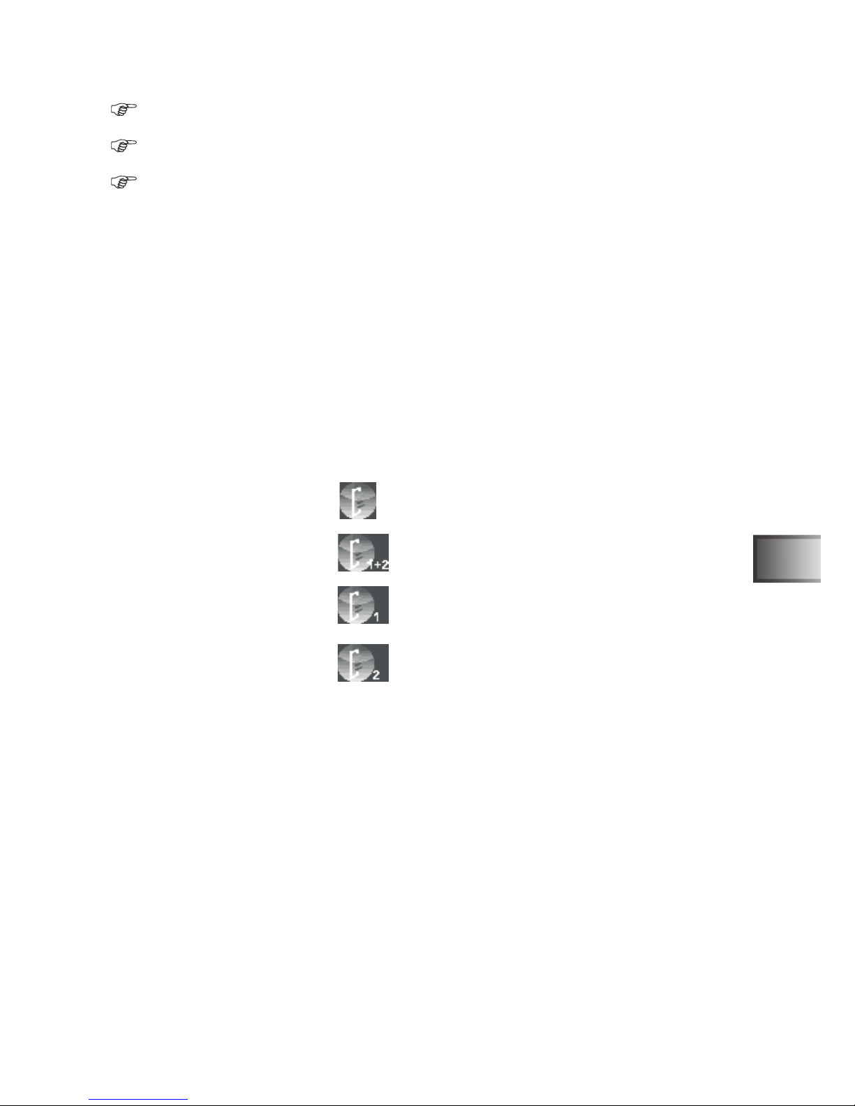
• Temperatur
• Intensität für beide Sitzplätze
• Intensität Platz 1
• Intensität Platz 2
Temperatur einstellen
(30 bis 70°C für Strahlerbetrieb - 30 bis 50°C für Folienbetrieb)
Navigieren Sie zum Menüpunkt Temperatur. Durch Bestätigen mit der OK-Taste 3 gelangen Sie in das Untermenü, in dem Sie mit dem Touch-Wheel 4 Ihren Wunsch-Temperaturwert einstellen können. Bestätigen Sie Ihren
Wunsch-Temperaturwert mit der OK-Taste 3.
Intensität (für beide Sitzplätze) einstellen (Stufe 0 bis 8)
Bestätigen Sie den Menüpunkt mit der OK-Taste 3. Dadurch gelangen Sie in das Untermenü, in dem Sie mit
dem Touch-Wheel 4 Ihre Einstellung vornehmen können. Bestätigen Sie Ihre Auswahl mit der OK-Taste 3.
Intensität (für einzelne Sitzplätze) einstellen (Stufe 0 bis 8)
Bestätigen Sie den Menüpunkt mit der OK-Taste 3. Dadurch gelangen Sie in das Untermenü, in dem Sie mit
dem Touch-Wheel 4 Ihre Einstellung vornehmen können. Bestätigen Sie Ihre Auswahl mit der OK-Taste 3.
Gebrauchsanweisung für den Anwender S. 17/22
DE
WORLD OF WELLNESSWORLD OF WELLNESS

14.4 Tageslicht einstellen (Kabinenlicht)
Navigieren Sie im Homescreen zum Menüpunkt Tageslicht. Durch Bestätigen mit der OK-Taste 3 gelangen
Sie in das Untermenü, in dem Sie Ihre Einstellung vornehmen können.
Sie können das Kabinenlicht mit dem wave.com4 touch Bedienteil dimmen, in dem Sie mit dem Touch-Wheel
4 Ihren Wunsch-Prozentwert einstellen. Bestätigen Sie Ihren Wunsch-Prozentwert mit der OK-Taste 3.
14.5 Farblicht einstellen
Farbe auswählen
Navigieren Sie zum Menüpunkt Farblicht. Durch Bestätigen mit der OK-Taste 3 gelangen Sie in das Untermenü, in dem Sie mit dem Touch-Wheel 4 auswählen können, welche Farbe gezeigt werden soll.
Die eingestellte Farbe wird im Homescreen angezeigt.
Helligkeit einstellen
Zusätzlich kann man über den Menüpunkt Farblicht die Helligkeit einstellen. Durch Longpress auf die Taste OK
3 im Farbwahlmenü gelangen Sie in die Helligkeitseinstellung. Führen Sie hier Ihre Einstellung durch. Bestätigen Sie mit der OK-Taste 3 Ihre Wahl.
14.6 Lüfter
Navigieren Sie zum Menüpunkt Lüfter.
• Lüfter an wave.com4 Sauna: mit der OK-Taste 3 kann der Lüfter ein und ausgeschalten werden.
• Lüfter an wave.com4 Infra: mit der OK-Taste 3 gelangen Sie in die Einstellung der Lüfter Intensität
14.7 Musik
Navigieren Sie zum Menüpunkt Musik. Durch Bestätigen mit der OK-Taste 3 gelangen Sie in das Untermenü,
in dem Sie mit dem Touch-Wheel 4 Ihre Wunsch-Lautstärke einstellen können. Bestätigen Sie Ihre WunschLautstärke mit der OK-Taste 3.
15 Musik Shortkeys
Mit den Shortkeys: Play/Pause 7, nächster Titel 6 und Lautstärke 5 kann der MP3-Player direkt gesteuert
werden.
Gebrauchsanweisung für den Anwender S. 18/22

16 Programme einstellen
Navigieren Sie im Homescreen zum Menüpunkt Programme. Durch Druck auf die OK-Taste gelangen Sie in das
Untermenü.
16.1 Infrarot:
Hier können Sie aus einem der folgenden Infrarotprogramme wählen:
o Aus
o Entspannung
o Aufwärmen
o Ausdauer kurz
o Ausdauer lang
16.2 Farblicht:
Hier können Sie folgende Einstellungen vornehmen:
o Modus (manuell/automatisch):
• Manuell:
Die Einstellungen, die im Menü Farblicht (Farbe) eingestellt wurden, werden übernommen und vom S&L System
ausgeführt.
• Automatisch:
Der Farbwechsel erfolgt automatisch nach den eingestellten Zeiten.
o Farbdauer (Minuten, einstellbar von 1 bis 20)
o Überblendzeit der Farben (Sekunden, einstellbar von 1 bis 20)
17 AllgemeineEinstellungen/Kongurationen
Durch Longpress der C-Taste 2 gelangen Sie in das Kongurationsmenü des wave.com4 touch Bedienteils.
17.1 Allgemein
o Datum/Uhr
o Displayhelligkeit Werkseinstellung 10
o Menü Sprache Werkseinstellung deutsch
o Feedback Werkseinstellung ein
o Auto Hauptfenster Zeit Werkseinstellung 10
17.2 Techniker
nur für Fachpersonal zur Installation des Gesamtsystems
17.3 Datum/Uhr einstellen
Der Navigationsbalken springt nach Drücken der OK-Taste 3 automatisch in die nächste Zeile.
Navigieren Sie zum Menüpunkt Datum/Uhr. Durch Drücken der OK Taste 3 gelangen Sie in die Einstellungen.
Die blau hinterlegte Zeile ist einstellbar. Mit dem Touch-Wheel 4 können Sie die Stunden-, Minuten- und Sekunden bzw. das Datum einstellen. Bestätigen Sie Ihre Wahl mit der OK-Taste 3.
Gebrauchsanweisung für den Anwender S. 19/22
DE
WORLD OF WELLNESSWORLD OF WELLNESS

17.4 Displayhelligkeit einstellen
Navigieren Sie zum Menüpunkt Displayhelligkeit. Durch Drücken der OK Taste 3 gelangen Sie in die Einstellungen. Mit dem Touch-Wheel 4 können Sie die Displayhelligkeit in Stufen (1-10) einstellen. Bestätigen Sie Ihre
Wahl mit der OK-Taste 3.
17.5 Menü Sprache
Navigieren Sie zum Menüpunkt Menüsprache. Durch Drücken der OK Taste 3 gelangen Sie in die Einstellungen.
Mit dem Touch-Wheel 4 können Sie Ihre Sprache auswählen. Bestätigen Sie Ihre Wahl mit der OK-Taste 3.
17.6 Feedback
Navigieren Sie zum Menüpunkt Feedback. Durch Drücken der OK Taste 3 aktivieren/deaktivieren Sie das Feedback.
17.7 Auto-Hauptfenster-Zeit
Navigieren Sie zum Menüpunkt Auto Hauptf.. Durch Drücken der OK Taste gelangen Sie in die Einstellungen.
Mit dem Touch-Wheel 4 können Sie die Zeit in Sekunden (8-15) einstellen. Bestätigen Sie Ihre Wahl mit der OK-
Taste.
18 Vorwahlzeit einstellen
Sie können die Vorwahlzeit in 15-Minuten-Schritten einstellen. Die minimale Vorwahlzeit beträgt eine Stunde, die
maximale Vorwahlzeit 24 Stunden.
Starten Sie zuvor die Funktionen, die nach Ablauf der eingestellten Vorwahlzeit eingeschalten werden sollen.
• Aktivieren Sie beispielsweise den Saunabetrieb (Temperatur wird angezeigt, der Saunaofen heizt)
• Navigieren Sie zum Menüpunkt Programme und danach auf Vorwahlzeit.
• Durch Bestätigen mit der OK-Taste 3 gelangen Sie in das Untermenü, in dem Sie mit dem Touch-Wheel 4
Ihren Wunschwert einstellen können.
• Bestätigen Sie Ihre gewünschte Vorwahlzeit mit der OK-Taste 3.
• Aktivieren Sie nun die Vorschaltzeit durch Longpress der Taste 1 .
• Das wave.com4 touch Bedienteil wechselt jetzt in einen Standby-Modus.
• Es erscheint die Anzeige „Einschalten in...“ und der Timer läuft.
Nach Ablauf der ersichtlichen Zeit wird der Saunaofen (Temperaturwert wird aus zuletzt ausgeführter Kongurati-
on übernommen.) gestartet.
Sie können diesen Modus jederzeit unterbrechen, indem Sie die Taste 1 drücken (Longpress).
Die Vorwahlzeit muss vor jeder Nutzung erneut eingestellt werden - die Einstellung bleiben nicht bestehen!
Bei Einschalten via Vorwahlzeit werden folgende Komponenten nicht eingeschaltet:
* Kabinenlicht
* Farblicht
* Lüfter
Gebrauchsanweisung für den Anwender S. 20/22
WORLD OF WELLNESS

19 Technische Daten
Stromversorgung wird über das Leistungsteil eines o. a. Gerätes bezogen ausgenommen
Sound & Light
Betriebsspannung 12-24Vdc
Leistung max. 5,6W
Standby-Aufnahme max. 1 W
Maße Display: 3,5“
Lautsprecher 2x5W 8Ohm
Umgebungsbedingungen 0°C – 55°C, maximal 99% relative Luftfeuchte, nicht kondensierend
Einbaumaße Ausschnitt 213 mm x 82 mm x 36 mm,
Frontglas Maße: B x H x T 219,50 mm x 92 mm x 3,50 mm
Gewicht ca 400g ohne Anschlussleitungen und Zubehör
Montage- und Gebrauchsanweisung S. 21/22
WORLD OF WELLNESS
DE

20 Garantiebestimmungen
sentiotec GmbH ist von der Qualität ihrer Produkte überzeugt und davon wollen wir Sie in Zukunft protieren lassen! Wir leisten daher 5 Jahre Garantie im privaten Bereich und 2 Jahre bei gewerblicher Nutzung.
Voraussetzung für diese Garantieleistung:
• Die Steuergeräte wurden von einem autorisierten Fachbetrieb installiert;
• Die Geräte werden gemäß der sentiotec-Bedienungsanleitungen bedient;
• Der Garantieanspruch geht innerhalb der Garantiezeit bei sentiotec ein.
Von der Garantie ausgenommen sind:
Mängel oder Schäden, die durch einen nicht bestimmungsgemäßen Gebrauch entstanden sind.
Die Garantiezeit beginnt ab der Rechnungserstellung des Kabinenherstellers.
Vorraussetzung hierfür ist die Vorlage der Originalrechnung.
Die Garantiefrist wird durch Garantieleistungen weder verlängert noch erneuert.
Sollte Ihr Gerät einen Defekt aufweisen, dann retournieren Sie es an Ihren Saunahändler.
Änderungen, welche ohne die ausdrückliche Zustimmung des Herstellers durchgeführt werden, führen zu Garantieverlust!
Die Garantiefrist wird durch Garantieleistungen weder verlängert noch erneuert. Sollte Ihr Gerät einen Defekt aufweisen, dann retournieren Sie es an Ihren Saunahändler.
Diese Garantie umfasst die Vergütung von defekten Geräteteilen mit Ausnahme normaler Verschleißerscheinungen.
Bei Beanstandungen ist das Gerät in Originalverpackung oder einer entsprechend geeigneten Verpackung unsere
Service-Abteilung einzuschicken.
21 Entsorgung
Bitte entsorgen Sie Verpackungsmaterialien nach den gültigen Entsorgungsrichtlinien.
Altgeräte enthalten wieder verwendbare Materialien. Geben Sie deshalb Altgeräte nicht einfach auf die nächste
Mülldeponie, sondern erkundigen Sie sich bei Ihrer Stadt- oder Gemeindeverwaltung nach der Möglichkeit der
Wiederverwertung.
22 Lieferumfang
• wave.com4 touch Bedienteil (inkl. integriertem MP3-Player, exkl. USB-Stick)
• RJ12 modulares Flachbandkabel 6pol., 3m
• Montagematerial
• Jumpersatz zur Konguration der Leistungsteile
Montage- und Gebrauchsanweisung S. 22/22
WORLD OF WELLNESS
wave.com4 touch II
ALL-IN-ONE OPERATING ELEMENT
WC4-B-TC2
Instructions for installation and use
English
All-in-One operating element which scores with its self-assured
design.
Version 11/13 Ident-Nr. 1-026-981
EN

Table of contents
1 General safety information 3
2 Use as intended 4
3 General description of function 4
3.1 Table of available functions 4
4 Cleaning of the operating element 5
5 Installation of the operating element 6
6 Electrical connection – only for experts 7
6.1 Rear view - wave.com4 touch 7
6.2 Connection of loudspeaker and terminal assignment 7
6.3 Block wiring diagrams 8
7 Congurationofthepowerelementsforconnectiontothewave.com4touch 9
7.1 Wave.com4 sauna basic module WC4-B-L 9
7.2 Sound & Light WC4-SL-L 9
7.3 wave.com4 Infra WC4-IRX-P 9
7.3 Integration of conventional operating elements 10
8 Commissioning – only for experts 11
9 Engineer’s settings – only for experts 11
9.1 Carrying out settings in the engineer’s menu 11
10 Description of the options in the engineer’s menu 12
10.1 wave.com4 sauna control option 12
10.2 wave.com4 sauna control- remote contact option 12
10.3 Infrared option 12
10.4 wave.com4 Infra remote start option 12
10.5 Cabin light option 13
10.6 Max. run time option 13
10.7 Factory settings 13
10.8 Audio source option 13
10.9 Audio shufe option 13
11 Software update – only for experts 14
12 Operating and display elements 15
12.1 Menu 16
13 Switching on 16
14 General user guidance 17
14.1 Setting the sauna temperature 17
14.2 Setting humidity 17
14.3 Infrared settings 17
14.4 Setting daylight (cabin light) 18
14.5 Setting the colour light 18
14.6 Ventilator 18
14.7 Music 18
15 Music Short keys 18
16 Setting programs 19
16.1 Infrared 19
16.2 Colour light 19
17 Generalsettings/congurations 19
17.1 General 19
17.2 Engineers 19
17.3 Setting date/time 20
17.4 Setting display brightness 20
17.5 Menu language 20
17.6 Feedback 20
17.7 Auto main window time 20
18 Setting pre-set time 20
19 Technical data 21
20 Warranty clauses 22
21 Disposal 22
22 Scope of supply 22
Instructions for installation and use P. 2/22

1 General safety information
Meaning of symbols used in the instructions for installation and use:
WARNING:
The possibility of serious or even fatal injury exists in the event of disregarding.
CAUTION:
The possibility of slight to moderate injury or material damage exists in the event of disregarding.
TIP:
Gives tips for use and useful information.
Store these instructions for installation and use carefully near to the operating unit in order to be able to
refer to safety tips and operating information at any time.
• Improper assembly can constitute a re risk.
• Electrical connection may only be executed by qualied experts.
• The wiring diagram must be complied with during connection.
• Before the operating element is commissioned, it must be veried that all connections are rmly connected.
• This device is not intended for use by persons (including children) with limited psychological, sensory or
mental capacities or a lack of experience and/or knowledge, unless they are supervised by a person
responsible for their safety.
• Children should be supervised to ensure that they do not play with the device.
• The device is not appropriate for the direct control of sauna heating devices! Fire hazard!
• Keep these instructions for assembly and use carefully in proximity to the control unit in order to be able to
refer to safety tips and important information at any time.
• Also heed the special safety instructions in the individual chapters.
• If specic problems occur which are not sufciently dealt with in these instructions for use, please contact
your supplier for the sake of your own safety.
• Unauthorised modications or alterations to this sauna control unit are not permitted for safety reasons.
• Read the installation instructions carefully before assembling the device. This will enable you to make use of
all benets which the device has to offer and prevent damage.
• Due to the high temperatures and condensate in the sauna cabin, the wave.com4 touch operating unit is not
suitable for installation in the sauna cabin.
• The operating instructions for the combinable devices of the wave.com4 series must be heeded and
constitute part of these instructions for use.
• The wave.com4 sauna control unit may only be connected under strict compliance with these instructions.
You must use the original cable supplied and original components. The standards (wire cross-section,
insulation, temperature class, etc.) are only safely complied with when these cables are used.
• Subject to technical changes.
Instructions for installation and use P. 3/22
EN
WORLD OF WELLNESSWORLD OF WELLNESS
2 Use as intended
The sole purpose of the wave.com4 touch operating element is to operate devices in the wave.com4 series.
In accordance with this provision, the wave.com4 touch operating element can be used in its full functionality.
The safety and usage information of the respectively connected devices also applies.
3 General description of function
The wave.com4 touch operating element automatically recognises connected devices. The respective
menu points appear according to the devices recognised.
Only connect and disconnect devices when the power is off.
The following operating modes and functions are available, dependent on the devices connected. See also
the table of available functions:
• Finnish operation
• Climate operation
• Infrared operation
• Sound and light effects
• Ventilator
• Cabin light
• Programmes
One or more of the devices stated below may be used for power supply:
• wave.com4 basic module (Finnish sauna)
• wave.com4 basic module with extension module (combi sauna)
• wave.com4 Infra
3.1 Table of available functions:
Function
Device
Finnish
operation
Climate/
combioperation
Colour
light
Sound Cabin
light
3
Infrared
operation
Ventilator
4
2-sensor
regulation
WC4-B-L YES YES
1
YES
WC4-B-L +
WC4-H-PCB + YES YES
1
YES YES
WC4-B-L +
WC4-H-PCB +
WC4-H-F2
YES YES
1
YES YES YES
5
WC4-B-L +
WC4-H-PCB +
WC4-H-H
YES YES YES
1
YES YES
WC4-B-L +
WC4-H-PCB +
WC4-H-F2 +
WC4-H-H
YES YES YES
1
YES YES YES
5
WC4-IRX-P YES
1
YES YES YES
WC4-SL-L YES YES
2
1
External 8 Ohm loudspeaker necessary – not contained in scope of supply
2
The colour lamp is used as a loudspeaker. See also sound&light connection – only for experts.
3
When WC4-IRX-P and WC4-B-L are combined, a selection can be made in the system parameters with
regard to which device controls the cabin light.
4
When WC4-IRX-P and WC4-B-L are combined, a selection can be made in the system parameters with
regard to which device controls the ventilator.
5
The bench sensor must be activated in the system parameters.
Instructions for installation and use P. 4/22
WC4-B-L: wave.com4 basic module power module
WC4-H-PCB: wave.com4 extension circuit board
WC4-H-H: wave.com4 humidity sensor
WC4-H-F2: wave.com4 bench sensor
WC4-IRX-P: wave.com4 Infra power element
WC4-SL-L: wave.com4 sound&light colour light
If WC4-B-L is combined with WC4-SL-L, the WC4-SL-EXT cable set is also required. See also
‘Electrical connection – only for experts’.
wave.com4 sauna basic modules (WC4-B-L) with a production date prior to 12/2011 are not compatible
with the wave.com touch. The necessary software update can only be executed at the factory.
4 Cleaning of the operating element
Clean the operating element according to the degree of soiling.
Disconnect the entire control from the network.
Gently wipe the front of the operating element with a soft cloth (e.g. microbre cloth) slightly wetted with neutral
soapy water.
Do not clean the reverse and the circuit board behind it yourself under any circumstances. This may
damage the device. Ask service personnel if necessary.
Due to the high temperature and the condensate in the sauna cabin, the wave.com4 touch operating
element is not suitable for installation in the sauna cabin.
Instructions for installation and use P. 5/22
EN
WORLD OF WELLNESSWORLD OF WELLNESS
5 Installation of the operating element
A cut-out of 213 mm x 82 mm must be provided for the installation of the wave.com4 touch operating element,
into which the installation frame B is installed. In order to afx the frame, bend the brackets ’C’ with a
screwdriver as illustrated in the Figure. The installation depth of the wave.com4 touch operating element is 36
mm.
After wiring, (see wiring section) install the operating element A into frame B as in the Figure.
Assembly of installation frame
Installation of the operating element into the installation frame
Dimensions
Instructions for installation and use – only for experts P. 6/22
6 Electrical connection – only for experts
Also heed the instructions in the operating and installation instructions of the power elements used.
6.1 Rear view wave.com4 touch
6.2 Connection of loudspeaker and terminal assignments
LSL+ Loudspeaker left +
LSL- Loudspeaker left –
LSR+ Loudspeaker right +
LSR- Loudspeaker right –
When the sound & light is used with the wave.com4 touch,
the loudspeakers can be connected to the wave.com4 touch
(terminal block C).
Use of the MP3 player integrated into the sound & light (connection of the loudspeaker of the colour lamp to the
power element of the S&L in accordance with the S&L operating instructions) and the amplier is possible
(can be selected in the system menu).
LSL+ Loudspeaker left + brown
LSL- Loudspeaker left – blue
LSR+ Loudspeaker right + grey
LSR- Loudspeaker right – black
Switch B is currently not in use and reserved for subsequent applications.
rear view
terminal block C
The individual modules are connected to one another via the
6-pin RJ12 cable.
The bus cable is inserted into jack A at the operating element.
See also block wiring diagrams.
The loudspeakers are connected via terminal block C.
Instructions for installation and use – only for experts P. 7/22
EN
WORLD OF WELLNESSWORLD OF WELLNESS
6.3 Block wiring diagrams
wave.com4 sauna basic modules (WC4-B-L) with a production date prior to 12/2011 are not compatible
with the wave.com4 touch. The necessary software update can only be executed at the factory.
The individual devices are connected via 6-pin RJ12 cables (D and E). A connection cable D is contained in the
scope of supply of the wave.com4 touch operating element. An O-CX-C10 (E) connection cable must be
ordered for each power element for the connection of several power elements.
If only the wave.com4 sound & light and the wave.com4 sauna basic module are used, a Y-connector F is also
required. This is contained in the WC4-SL-EXT set.
The data cable E is also contained in the WC4-SL-EXT set
Block wiring diagram, fully extended
sound & light block wiring diagram with wave.com4 Sauna
6-pin operating
element
6-pin operating
element
Instructions for installation and use – only for experts P. 8/22

7 Congurationofthepowerelementsforconnectiontothe
wave.com4 touch
7.1 wave.com4 sauna basic module WC4-B-L
wave.com4 sauna basic modules (WC4-B-L) with a production date prior to 12/2011 are not compatible
with the wave.com4 touch. The necessary software update can only be executed at the factory.
The JPBM jumper is contained in the scope of supply of the wave.com4 touch. Install these into the 6-pin socket
connector as shown in the gure.
7.2 Sound & Light WC4-SL-L
The JPSL jumper set at the factory must remain in its position.
If several sound & lights (up to four devices are possible) are used, the JPSL jumper must remain in position for
all devices connected to the bus, contrary to the instructions in the operating and installation instructions.
7.3 wave.com4 Infra WC4-IRX-P
Install the jumpers enclosed with the wave.com4 touch at pin connector socket OPT3 on JP1. Where several
wave.com4 Infra power elements are used (up to four devices are possible) the conguration can be found in
the operating and installation instructions of the wave.com4 Infra.
Jumper basic module
Jumper SL
Jumper Infra
Instructions for installation and use – only for experts P. 9/22
EN
WORLD OF WELLNESSWORLD OF WELLNESS

7.3 Integration of conventional operating elements
With V.1.04 it is possible to integrate conventional operating elements into your sauna system. These then display the operating mode selected by you. You can make or change settings on the operating element - the operating elements communicate with your wave.com4 touch operating elements.
Operating elements which can be used:
WC4-B-S/W/D/H WC4-IRX-S/W/D/H WC4-SL-S/W/H/D
In order to use this function with the WC4-SL-S/W/H/D operating element, if produced prior to 11/2012
your operating element may require a software update. It is necessary to send in the WC4-SL-S/W/H/D
operating element for this purpose.
Before connecting the WC4-SL-S/W/D/H operating element, the operating element must have been
previously congured to BUS conguration. Proceed as follows here:
* Unplug operating element from power element (RJ10 4/4).
* Keep +/- buttons depressed simultaneously and plug the RJ10 4/4 data cable in again.
* Select ‘TC4‘ with the +/- buttons.
* Conrm the selection with the Mode button.
* Select ‘Po0‘ with the +/- buttons.
* Conrm the selection with the Mode button.
The conventional operating elements WC4-B-S/W/D/H, WC4-IRX-S/W/D/H, WC4-SL-S/W/H/D can be
installed within your sauna cabin. Please observe the comments in the respective operating instructions to
this end. The environmental parameters (see Technical Data of the respective operating instructions) must
be complied with under all circumstances.
When 2 operating elements are used on the bus (possible for Wave.com4 and Wave.com4 Infra- RJ10 4/4
connection and also S&L) it must be considered that each individual operating element is assigned to a different
bus address in each instance. To this end, observe further comments in the respective operating instructions
(Wave.com4 and Wave.com4 Infra)
Instructions for installation and use – only for experts P. 10/22

8 Commissioning – only for experts
Check that all modules used are correctly connected.
Check whether all jumpers are correctly set on the individual devices. Changes to jumpers are not
recognised when the network voltage is applied.
The individual modules of the wave.com4 touch operating element are recognised automatically after
application of network voltage.
The modules recognised are displayed in the display by their respective menu points. See engineer’s settings
and operating instructions for the user.
9 Engineer’s settings – only for experts
The nal conguration of the overall system is undertaken in the engineer’s settings. The available
options are specied by the connected modules.
Please observe the operating instructions for users section (display and operating elements)
9.1 Carrying out settings in the engineer’s menu
1
2
3
4
5
67
8
9
10
11
Front glass operating & display elements
The control is activated by a long press on OK 1
and the home screen with the available settings
options is displayed. The engineer’s menu is
activated by a long press on the C button 2.
Navigate to the ‘Engineers‘ menu point with the
touch wheel 4. Conrm with the OK button 3.
Module settings can now be made here.
To select a menu point, navigate to the option to
be changed with the touch wheel 4 and select
this with OK 3. Press C 2 to go back a level.
Instructions for installation and use – only for experts P. 11/22
EN
WORLD OF WELLNESSWORLD OF WELLNESS

10 Description of the options in the engineer’s menu
Depending on which modules or power elements are connected, the respective menu points are displayed
or hidden.
Depending on which settings are undertaken in the engineer’s menu, individual menu points are
displayed or hidden.
Factory settings are written in bold
10.1 wave.com4 sauna control option
• Evaporator Off/on When the extension circuit board is connected (WC4-H-PCB)
deactivates the evaporator output and hides the ‘Humidity‘ menu point
in the home screen.
• Ventilator On/off Activates the ventilator output on the wave.com4 sauna control basic
module. The ventilator output of the wave.com4 Infra is then automatically
deactivated.
• Bench sensor Off/on
• Res5 function Nw (Evaporator water-failure function)/Rs (remote start). Activates the
remote start on the wave.com4 sauna control basic module. The water failure detection is then no longer available. The remote start input of
the wave.com4 Infra is then automatically deactivated.
Also observe the information in the operating and installation instructions of the wave.com4 sauna
control
10.2 wave.com4 option – sauna control- remote contact
Here you can specify whether the Wave.com4 sauna control should remain switched on after
termination of the remote contact voltage:
Switch on (select = ‘On‘)
Switch off (select ‘Off‘)
10.3 Infrared option
Ventilator Off/on Activates the ventilator output on the wave.com4 Infra. The ventilator
output of the wave.com4 sauna control basic module is then
automatically deactivated.
Switching output 1 Off/on Activates the potential -free OPT1 output. This switches off
automatically upon changeover into stand-by mode.
Switching output 2 Off/on Activates the potential-free OPT2 output. This switches off
automatically upon changeover into stand-by mode.
Remote start Off/on; Activates the remote start input on the wave.com4 Infra. The remote
start input of the wave.com4 sauna control basic module is then
automatically deactivated. Please observe the instructions in the
operating and installation instructions of the wave.com4 Infra.
10.4 wave.com4 Infra remote start option
Here you can preset the control whether the Wave.com4 Infra (infrared control) should react to
remote start or not. The Wave.com4 Infra infrared control is started remotely by means of a switch.
Further information relating to the Wave.com4 Infra remote start can be found in the operating instructions
of the Wave.com4 Infra.
Instructions for installation and use – only for experts P. 12/22

This function can only be used with an update of the WC4-IRX-P power element. It is necessary to send in
the WC4-IRX-P power element for this purpose.
10.5 Cabin light option
This allows you to select via which module (wave.com4 basic with/without humidity module or wave.com4 Infra)
you obtain the cabin light.
o SAN (wave.com4 basic (or basic with humidity extension))
o INF (wave.com4 Infra)
10.6 Max. run time option:
You can change the max. run time here.
o 6h (in acc. with standard EN 60335-2-53 and EN 60335-1 maximum operating period in the
domestic sector)
o 12h (in acc. with standard EN 60335-2-53 and EN 60335-1 maximum operating period in the
commercial sector)
10.7 Factory settings:
Long press on OK 3
You can reset the wave.com4 touch operating element to its software delivery state here. After conrming this
option, switch the device off and then on again.
10.8 Audio source option
Here you can select which USB audio source you wish to use:
Select Sound&Light (optional WC4-SL-L necessary) as an audio source
Select wave.com4 touch operating element as an audio source
Multiple selection is not possible. The selection of an audio source respectively deactivates the other
audio source.
10.9AudioShufeoption
The shufe playback (audio) mode is activated when this option is selected. Thus, all MP3 les on your USB
stick are played backed at random.
Any folder structure which may exist on your USB stick is disregarded here, i.e. a complete folder cannot
be played back in shufe mode.
Instructions for installation and use – only for experts P. 13/22
EN
WORLD OF WELLNESSWORLD OF WELLNESS

11 Software update – only for experts
Note the conguration. The settings are reset by the software update
The necessary data and program les are provided on request.
Proceed as follows to perform the update:
-> Switch the device on.
-> Place the USB stick with the update data into the USB port of the wave.com4 touch
The USB stick must contain no other data except for the update
-> In the engineer’s menu navigate to the factory settings menu point.
-> Start the software update by a long press on C 2
-> Wait until the update is complete. Do not disconnect the device from the mains under any circumstances
during the software update.
-> After the update the wave.com4 touch goes into standby mode.
The software can be updated by your sauna dealer via the USB port of the Touch. Please nd out about
software updates available.
A suitable USB stick for the wave.com4 touch operating element is optionally available (WC4-USB-M):
Instructions for installation and use – only for experts P. 14/22
WORLD OF WELLNESS

12 Operating and display elements
1 On/off button.
When the button is illuminated in white, the system is in standby mode.
2 C button
3 OK button
4 Touch wheel (navigation wheel)
5 Shortkey MP3 player volume
6 Shortkey MP3 player track forward
7 Shortkey MP3 player play/pause
8 Line-In 3.5 mm stereo handle
9 USB connection
a Display
b LED wheel illumination (with advancing
nger rotation dots are illuminated in
the LED circle)
1
2
3
4
5
67
8
9
10
11
Front glass operating and display elements
Instructions for use for the user P. 15/22
EN
WORLD OF WELLNESSWORLD OF WELLNESS

12.1 Menu
Sauna Temp 30°C to 110°C
Humidity 0% to 100%
Infrared status Program number, temperature or intensity level
Daylight 0% to 100%
Colour light status automatic mode or colour number
Music Pause, play and stop
Program
13 Switching on
You can switch the system on and off by a long press on the ON/OFF button 1.
Ventilator on/off or adjustable (only for wave.com4 Infra)
Instructions for use for the user P. 16/22

14 General user guidance
The current cabin values are displayed on the home screen.
You always get back to one menu level by pressing the C button 2.
The functions can be directly activated or deactivated in the home screen with the C button 2.
14.1 Setting the sauna temperature
Navigate to the ‘Sauna temp.‘ menu point in the home screen. Conrming with the OK button 3 takes you to the
submenu where you can set your desired temperature value with the touch wheel 4. Conrm your desired temperature with the OK button 3
14.2 Setting humidity
Navigate to the humidity menu point in the home screen. Conrming with the OK button 3 takes you to the sub-
menu where you can set your desired humidity value with the touch wheel 4. Conrm your desired humidity value with the OK button 3.
14.3 Infrared settings
Selecting the ‘Infrared‘ menu point and conrming with the OK button (3) takes you to the submenu.
• Temperature
• Intensity for both seats
• Intensity seat 1
• Intensity seat 2
Setting the temperature
(30 to 70°C for radiator operation - 30 to 50°C for foil operation)
Navigate to the ‘Temperature‘ menu point. Conrming with the OK button 3 takes you to the submenu where you
can set your desired temperature value with the touch wheel 4. Conrm your desired temperature value with the
OK button 3.
Setting intensity (for both seats) (level 0 to 8)
Conrm the menu point with the OK button 3. This takes you to the submenu where you can make your settings
using the touch wheel 4. Conrm you selection with the OK button 3.
Setting intensity (for individual seats) (level 0 to 8)
Conrm the menu point with the OK button 3. This takes you to the submenu where you can make your setting
with the touch wheel 4. Conrm your selection with the OK button 3.
Instructions for use for the user P. 17/22
EN
WORLD OF WELLNESSWORLD OF WELLNESS

14.4 Setting daylight (cabin light)
In the home screen, navigate to the ‘Daylight‘ menu point. Conrming with the OK button 3 takes you to the
submenu where you can make your setting.
You can dim the cabin light with the wave.com4 touch operating element by setting your desired percentage
value with the touch wheel 4. Conrm your desired percentage value with the OK button 3.
14.5 Setting the colour light
Selecting colour
Navigate to the colour light menu point. Conrming with the OK button 3 takes you to the submenu where
you can select with the touch wheel 4 which colour should be shown. The set colour is displayed in the home
screen.
Setting brightness
You can also set the brightness via the colour light menu point. A long press on the OK button 3 in the colour
selection menu takes you to the brightness setting. Make your setting here. Conrm your selection with the OK
button 3.
14.6 Ventilator
Navigate to the fan menu point.
• Ventilator on wave.com4 Sauna: the ventilator can be switched on and off with the OK button 3.
• Ventilator on wave.com4 Infra: the OK button 3 takes you to the ventilator intensity setting
14.7 Music
Navigate to the music menu point. Conrming with the OK button 3 takes you to the submenu where you can
set your desired volume with the touch wheel 4. Conrm your desired volume with the OK button 3.
15 Music short keys
The MP3 player can be controlled directly with the short keys: play/pause 7, next title 6 and volume 5.
Instructions for use for the user P. 18/22

16 Setting programs
Navigate to the ‘Programs‘ menu point in the home screen. Pressing the OK button takes you to the submenu.
16.1 Infrared:
You can select from one of the following infrared programs here:
o Off
o Relaxation
o Warm up
o Endurance short
o Endurance long
16.2 Colour light:
The following settings can be made here:
o mode (manual/automatic):
• Manual:
The settings made in the colour light (colour) menu are adopted and executed by the S&L system.
• Automatic:
The colour changes automatically according to the set times.
o Colour duration (minutes, can be set from 1 to 20)
o Colour fading time (seconds, can be set from 1 to 20)
17 Generalsettings/congurations
A long press on the C button 2 takes you to the conguration menu of the wave.com4 touch operating element.
17.1 General
o Date/time
o Display brightness factory setting 10
o Menu language factory setting German
o Feedback factory setting on
o Auto main window time factory setting 10
17.2 Engineer
Only for experts for the installation of the entire system
17.3 Setting date/time
The navigation bar automatically jumps to the next line after pressing the OK button 3.
Navigate to the ‘Date/time‘ menu point. Pressing the OK button 3 will take you to the settings. The line with a
blue background can be set. You can set hours, minutes and seconds or the date with the touch wheel 4. Conrm your selection with the OK button 3.
Instructions for use for the user P. 19/22
EN
WORLD OF WELLNESSWORLD OF WELLNESS

17.4 Setting display brightness
Navigate to the display brightness menu point. Pressing the OK button 3 will take you to the settings. You can
set the display brightness in levels (1-10) with the touch wheel 4. Conrm your selection with the OK button 3.
17.5 Menu language
Navigate to the ‘Menu language‘ menu point. Pressing the OK button 3 will take you to the settings. You can select your language with the touch wheel 4. Conrm your selection with the OK button 3.
17.6 Feedback
Navigate to the Feedback menu point. Pressing the OK button 3 will activate/deactivate the feedback.
17.7 Auto main window time
Navigate to the ‘Auto main window‘ menu point. Pressing the OK button will take you to the settings. You can set
the time in seconds (8-15) with the touch wheel 4. Conrm your selection with the OK button.
18 Setting pre-set time
The pre-set time can be set in 15-minute steps. The minimum pre-set time is one hour, the maximum pre-set time
24 hours.
Start the functions which should be switched on when the set pre-set time has elapsed in advance.
* For example, activate sauna operation (the temperature is displayed, the sauna heater heats up)
* Navigate to the ‘Programmes‘ menu point and then to pre-set time.
* Conrming with the OK button 3 takes you to the sub-menu which allows you to set your desired value
with the touch wheel 4.
* Conrm your desired pre-set time with the OK button 3.
* Now activate the pre-switching time with a long press on button 1 .
* The wave.com4 touch operating element now goes into stand-by mode.
* The ‘switch on in...’ display appears and the timer operates.
The sauna heater (temperature value is taken from last executed conguration) starts after elapsing of the
visible time.
You can cancel this mode at any time by pressing button 1 (long press).
The pre-set time must be reset before every use- the settings are not stored.
The following components are not switched on when switch-on occurs via a pre-set time:
* Cabin light
* Colour light
* Ventilator
Instructions for use for the user P. 20/22
WORLD OF WELLNESS

19 Technical information
Power supply is obtained from the power element of one of the aforementioned
devices, except for Sound & Light
Operating voltage 12-24Vdc
Power rating max. 5,6W
Standby input max. 1 W
Display dimensions: 3,5“
Loudspeaker 2x5W 8Ohm
Ambient conditions 0°C – 55°C, maximum 99% relative air humidity, not condensing
Installation dimensions cut-out 213 mm x 82 mm x 36 mm,
Front glass dimensions: B x H x T 219,50 mm x 92 mm x 3,50 mm
Weight approx 400 g without connection cables and accessories
Instructions for installation and use P. 21/22
EN
WORLD OF WELLNESSWORLD OF WELLNESS
EN

20 Warranty clauses
sentiotec GmbH is convinced of the quality of its products and we want you to benet from this in future. We
therefore offer a 5-year warranty on products for domestic use and a 2-year warranty on products for industrial
use.
The prerequisites for this warranty are that:
• the control devices have been installed by an authorised specialist company;
• the devices are operated in accordance with the sentiotec operating instructions;
• the warranty claim is received by sentiotec within the warranty period.
The following are excluded from the warranty:
Defects or damage which have occurred due to use otherwise than as intended.
The warranty period begins when the product is invoiced by the cabin manufacturer.
Presentation of the original invoice is a prerequisite for this.
The warranty period is neither extended nor renewed by work done under warranty.
If your device is defective, return it to your sauna retailer.
Modications undertaken without the explicit consent of the manufacturer will invalidate the warranty.
This guarantee includes the replacement of defective device components, with the exception of normal wear
and tear.
In the case of complaints, the device must be sent to our service department in its original packaging or
appropriate packaging.
21 Disposal
Please dispose of packaging materials in accordance with the applicable disposal regulations.
Used devices contain reusable materials. Therefore please do not simply take used devices to the nearest waste
disposal site, instead ask your local council about recycling facilities.
22 Scope of supply
• wave.com4 touch operating element (incl. integrated MP3 player, excl. USB stick)
• RJ12 modular at ribbon cable 6 pin, 3m
• Installation material
• Jumper set for the conguration of the power elements
Instructions for installation and use P. 22/22
WORLD OF WELLNESS

wave.com4 touch II
SYSTÈME DE COMMANDE TOUT-EN-UN
WC4-B-TC2
INSTRUCTIONS DE MONTAGE ET D’UTILISATION
Français
Système de commande tout-en-un au design élégant
Version 11/13 Ident-Nr. 1-026-981
FR

Table des matières
1 Consignes générales de sécurité 3
2 Utilisation réglementaire 4
3 Description générale du fonctionnement 4
3.1 Tableau des fonctions disponibles 4
4 Nettoyage du système de commande 5
5 Montage du système de commande 6
6 Raccordement électrique – uniquement pour le personnel spécialisé 7
6.1 Vue arrière du système wave.com4 touch 7
6.2 Raccordement haut-parleurs et répartition des bornes 7
6.3 Schémas de bloc 8
7 CongurationdesunitésdepuissancepourleraccordementausystèmeWave.com4Touch 9
7.1 Module de base Wave.com4 Sauna WC4-B-L 9
7.2 Sound & Light WC4-SL-L 9
7.3 wave.com4 Infra WC4-IRX-P 9
7.4 Intégration de systèmes de commande traditionnels 10
8 Mise en service – uniquement pour le personnel spécialisé 11
9 Réglages techniques – uniquement pour le personnel spécialisé 11
9.1 Réglages des paramètres dans le menu technicien 11
10 Description des options disponibles dans le menu technicien 12
10.1 Option Système de commande de sauna wave.com4 12
10.2 Option contact à distance sur le système de commande de sauna wave.com4 12
10.3 Option infrarouge 12
10.4 Option démarrage à distance de l’unité wave.com4 Infra 12
10.5 Option éclairage de la cabine 13
10.6 Option durée max. 13
10.7 Réglages usine 13
10.8 Option source audio 13
10.9 Option Audio aléatoire 13
11 Mise à jour du logiciel – uniquement pour le personnel spécialisé 14
12 Élémentsdecommandeetd’afchage 15
12.1 Menu 16
13 Mise en marche du système de commande 16
14 Interface utilisateur générale 17
14.1 Réglage de la température du sauna 17
14.2 Réglage de l’humidité 17
14.3 Réglages infrarouge 17
14.4 Réglage de l’éclairage de jour (éclairage de la cabine) 18
14.5 Réglage de l’éclairage de couleur 18
14.6 Ventilateur 18
14.7 Musique 18
15 Touches de raccourci musique 18
16 Réglage des programmes 19
16.1 Infrarouge 19
16.2 Éclairage de couleur 19
17 Réglagesgénéraux/congurationsgénérales 19
17.1 Généralités 19
17.2 Menu technicien 19
17.3 Réglage de la date et de l’heure
17.4 Réglage de la luminosité de l’écran 20
17.5 Langue du menu 20
17.6 Feedback 20
17.7 Durée d’afchage automatique de la fenêtre principale 20
18 Réglage de la durée de temporisation 20
19 Caractéristiques techniques 21
20 Dispositions de garantie 22
21 Élimination 22
22 Contenu de la livraison 22
Instructions de montage et mode d‘emploi p. 2/22

1 Consignes générales de sécurité
Signicationdessymbolesutilisésdanslesinstructionsdemontageetd’utilisation:
ATTENTION :
en cas de non-respect, risque de blessure grave, voire mortelle.
PRUDENCE :
en cas de non-respect, risque de blessures moyennes ou légères et de dégâts matériels.
REMARQUE : donne des conseils d‘utilisation et des informations utiles.
Conservez soigneusement les présentes instructions de montage et d‘utilisation à proximité du
systèmedecommande,andepouvoirconsulteràtoutmomentlesconsignesdesécuritéetles
informations importantes concernant la manipulation.
• Un montage non réglementaire peut engendrer un risque d‘incendie !
• Le raccordement électrique peut être effectué uniquement par le personnel qualié.
• Le raccordement doit être effectué conformément au schéma de connexion.
• Avant de mettre le système de commande en service, vériez si toutes les ches de raccordement sont
correctement branchées.
• Cet appareil ne doit pas être utilisé par des personnes avec des capacités physiques, sensorielles et
mentales limitées ou présentant une expérience et/ou un savoir insufsant (y compris les enfants), sauf si
ces mêmes personnes se trouvent sous la surveillance d‘un tiers responsable de leur sécurité.
• Les enfants doivent être surveillés an de garantir que l’appareil n’est pas utilisé comme un jouet.
• L’appareil ne peut servir pour commander directement les appareils de chauffage de sauna ! Risque
d’incendie !
• Conservez soigneusement les présentes instructions de montage et d‘utilisation à proximité du système de
commande an de pouvoir consulter à tout moment les consignes de sécurité et les informations
importantes concernant la manipulation.
• Conformez-vous également aux consignes de sécurité spéciques gurant aux différents chapitres.
• En cas de problèmes particuliers non traités sufsamment en détail dans le présent manuel, veuillez vous
adresser à votre fournisseur pour votre propre sécurité.
• Pour des raisons de sécurité, aucune modication ou transformation délibérée du système de commande
de sauna ne peut être effectuée.
• Lisez attentivement les présentes instructions avant de procéder au montage du système de commande.
De cette façon, vous pourrez bénécier de tous les avantages offerts par l’appareil et éviter tout dommage.
• En raison des températures élevées et de l’eau de condensation présentes dans la cabine de sauna, le
système de commande wave.com4 touch ne peut être monté à l’intérieur de la cabine.
• Veuillez respecter les instructions d’utilisation des différents appareils combinables de la série wave.com4.
Ces instructions font partie intégrante du présent manuel.
• Le système de commande wave.com4 touch ne peut être raccordé que si ces instructions sont scrupuleu-
sement respectées ! Utilisez uniquement les câbles et pièces d’origine fournis. Seuls ces câbles sont
parfaitement conformes aux normes (section, isolation, catégorie de température, etc.).
• Sous réserve de modications techniques.
Instructions de montage et mode d‘emploi p. 3/22
FR
WORLD OF WELLNESSWORLD OF WELLNESS

2 Utilisation réglementaire
Le système de commande wave.com4 touch sert exclusivement à commander les appareils de la série
wave.com4. Il est donc impératif d’en tenir compte pour pouvoir proter pleinement de toutes les
fonctionnalités de ce système.
En outre, les consignes de sécurité et d’utilisation des différents appareils connectés restent valables.
3 Description générale du fonctionnement
Le système de commande wave.com4 touch reconnaît automatiquement les appareils connectés. Le
menu proposé varie donc en fonction de ces derniers. Veuillez brancher et débrancher les appareils
uniquement lorsque ceux-ci sont hors tension.
Selon les appareils connectés, les modes de fonctionnement et fonctions suivants sont accessibles. Voir
également le tableau des fonctions disponibles :
• Mode nlandais
• Mode climatisation
• Mode infrarouge
• Effets sons et lumières
• Ventilateur
• Éclairage de la cabine
• Programmes
L’alimentation peut être assurée via un ou plusieurs des appareils mentionnés ci-dessous:
• module de base wave.com4 (sauna nlandais) ;
• module de base wave.com4 avec extension (sauna combiné);
• wave.com4 Infra
3.1 Tableau des fonctions disponibles:
Appareil
Mode
nlandais
Mode climatisation/mode
combiné
Éclairage de
couleur
Sons Éclairage
de la
cabine
3
Mode
infrarouge
Ventilateur
4
Réglage 2
ventilateurs
WC4-B-L OUI OUI
1
OUI
WC4-B-L +
WC4-H-PCB + OUI OUI
1
OUI OUI
WC4-B-L +
WC4-H-PCB +
WC4-H-F2
OUI OUI
1
JA OUI OUI
5
WC4-B-L +
WC4-H-PCB +
WC4-H-H
OUI OUI OUI
1
OUI OUI
WC4-B-L +
WC4-H-PCB +
WC4-H-F2 +
WC4-H-H
OUI OUI OUI
1
OUI OUI OUI
5
WC4-IRX-P OUI
1
OUI OUI OUI
WC4-SL-L OUI OUI
2
1
Haut-parleurs externes de 8 ohms nécessaires – non fournis.
2
La lampe de couleur est utilisée comme haut-parleur. Voir raccordement système sound&light – uniquement pour le
personnel spécialisé.
3
Lorsque les appareils WC4-IRX-P et WC4-B-L sont utilisés conjointement, il est possible de déterminer dans les
paramètres système quel est l’appareil qui doit commander l’éclairage de la cabine.
4
Lorsque les appareils WC4-IRX-P et WC4-B-L sont utilisés conjointement, il est possible de déterminer dans les
paramètres système quel est l’appareil qui doit commander le ventilateur.
5
Le détecteur de banc doit être activé dans les paramètres système.
Instructions de montage et mode d‘emploi p. 4/22

WC4-B-L: module de base wave.com4 – module de puissance
WC4-H-PCB: module d’extension wave.com4
WC4-H-H: capteur d’humidité wave.com4
WC4-H-F2: détecteur de banc wave.com4
WC4-IRX-P: unité de puissance wave.com4 Infra
WC4-SL-L: lampe de couleur sound&light wave.com4
Si le système WC4-B-L est combiné à WC4-SL-L, le kit de câbles WC4-SL-EXT sera impérativement
nécessaire. Voir à ce sujet « Raccordement électrique – uniquement pour le personnel spécialisé »
Les modules de base wave.com4 Sauna (WC4-B-L) ayant été fabriqués avant décembre 2011 ne sont
pas compatibles avec le système wave.com touch. Le logiciel doit pour ce faire être mis à jour, une modication
qui ne peut être effectuée qu’en usine.
4 Nettoyage du système de commande
Nettoyez le système de commande lorsque celui-ci est souillé.
Débranchez l’ensemble du système de commande.
Nettoyez ensuite soigneusement la partie avant du système de commande à l’aide d’un chiffon doux légèrement
humidié (en microbres, par exemple) et de l’eau savonneuse.
Ne nettoyez jamais vous-même ni la partie arrière, ni la platine située à l’arrière. Cela pourrait entraîner
des dommages à l’appareil ! Si un tel nettoyage est nécessaire, faites appel à du personnel qualié.
En raison des températures élevées et de l’eau de condensation présentes dans la cabine de sauna, le
système de commande wave.com4 touch ne peut être monté à l’intérieur de la cabine.
Instructions de montage et mode d‘emploi p. 5/22
FR
WORLD OF WELLNESSWORLD OF WELLNESS

5 Montage du système de commande
Lors du montage du système de commande wave.com4 touch, prévoyez une ouverture de 213 mm x 82 mm
an de pouvoir venir y placer le cadre de montage B. Pour xer le cadre, pliez les pattes C à l’aide d’un
tournevis, comme indiqué sur l’illustration. La profondeur d’encastrement du système wave.com4 touch est de
36 mm.
Une fois le câblage effectué (voir paragraphe « Câblage »), insérez le système de commande A dans le
cadre B comme indiqué sur l’illustration.
Montage du cadre
Encastrement de l’élément de commande dans le cadre de montage
Dimensions
Instructions de montage uniquement pour le personnel spécialisé P. 6/22

6 Raccordement électrique – uniquement pour le personnel spécialisé
Veuillez également respecter les instructions de montage et d’utilisation des unités de puissance
utilisées.
6.1 Vue arrière du système wave.com4 touch
6.2 Raccordement haut-parleurs et répartition des bornes
LSL+ Haut-parleur gauche +
LSL- Haut-parleur gauche –
LSR+ Haut-parleur droit +
LSR- Haut-parleur droit –
Lors de l’utilisation du système sound & light en combinaison
avec le wave.com4 touch, les haut-parleurs peuvent être
connectés au wave.com4 touch (bornier C).
Il est également possible d’utiliser le lecteur MP3 intégré dans le système sound & light (raccorder le
haut-parleur à la lampe de couleur sur l’unité de puissance du système S&L, respectez le manuel S&L) ainsi
que l’amplicateur (sélectionnable dans le menu système).
LSL+ Haut-parleur gauche + Brun
LSL- Haut-parleur gauche – Bleu
LSR+ Haut-parleur droit + Gris
LSR- Haut-parleur droit – Noir
Pour l’instant, l’interrupteur B n’est pas utilisé. Il est réservé pour des applications ultérieures.
Vue arrière
Bornier C
Les différents modules sont raccordés entre eux grâce à un
câble RJ12 à 6 pôles.
Pour le système de commande, le câble bus est branché dans
la prise femelle A. Voir aussi schémas de bloc.
Raccordez les haut-parleurs via le bornier C.
Instructions de montage uniquement pour le personnel spécialisé P. 7/22
FR
WORLD OF WELLNESSWORLD OF WELLNESS

6.3 Schémas de bloc
Les modules de base wave.com4 Sauna (WC4-B-L) ayant été fabriqués avant décembre 2011 ne sont
pas compatibles avec le système wave.com4 touch. Le logiciel doit pour ce faire être mis à jour, une
modication qui ne peut être effectuée qu’en usine.
Le raccordement des différents appareils s’effectue via un câble RJ12 à 6 pôles (D et E). Le câble de raccordement D est fourni avec le système de commande wave.com4 touch. Si vous souhaitez raccorder plusieurs
unités de puissance, prévoyez un câble de raccordement O-CX-C10 (E) par unité.
Si seuls le système wave.com4 sound & light et le module de base wave.com4 Sauna sont utilisés, prévoyez un
raccord Y (F) supplémentaire. Celui-ci est fourni avec le système WC4-SL-EXT.
Le câble de données E est également fourni avec le système WC4-SL-EXT.
Schéma de bloc – capacités maximales
Schéma de bloc sound & light avec wave.com4 Sauna
Système de
commande 6 pôles
Système de
commande 6 pôles
Instructions de montage uniquement pour le personnel spécialisé P. 8/22

7 Congurationdesunitésdepuissancepourleraccordementau
système wave.com4 touch
7.1 Module de base wave.com4 Sauna WC4-B-L
Les modules de base wave.com4 Sauna (WC4-B-L) ayant été fabriqués avant décembre 2011 ne sont pas
compatibles avec le système wave.com4 touch. Le logiciel doit pour ce faire être mis à jour, une
modication qui ne peut être effectuée qu’en usine.
Le cavalier JPBM est fourni avec le système wave.com4 touch. Comme indiqué sur l’illustration, placez ce dernier sur la
règle à prises femelles à 6 pôles.
7.2 Sound & Light WC4-SL-L
Le cavalier JPSL est placé en usine. Il doit être conservé dans cette position.
Si plusieurs systèmes sound & light sont utilisés (jusqu’à quatre appareils), le cavalier JPSL doit, contrairement à ce qui est
indiqué dans le manuel, être conservé dans sa position pour tous les appareils connectés au bus.
7.3 wave.com4 Infra WC4-IRX-P
Placez le cavalier fourni avec le système wave.com4 touch en JP1 (au niveau de la prise OPT3). Si vous
utilisez plusieurs unités de puissance wave.com4 Infra (jusqu’à quatre appareils), conformez-vous à la
conguration préconisée par le manuel de montage et d’utilisation du système wave.com4 Infra.
Cavalier module de base
Cavalier SL
Cavalier Infra
Instructions de montage uniquement pour le personnel spécialisé P. 9/22
FR
WORLD OF WELLNESSWORLD OF WELLNESS

7.3 Intégration de systèmes de commande traditionnels
Grâce à V.1.04, il est possible d’intégrer les systèmes de commande traditionnels dans votre système de
sauna. Le mode de fonctionnement que vous avez sélectionné est indiqué sur ces derniers. Vous pouvez
paramétrer ou modier les réglages sur le système de commande – les différents systèmes communiquent en
effet avec votre wave.com4 touch.
Systèmes de commande pouvant être utilisés:
WC4-B-S/W/D/H WC4-IRX-S/W/D/H WC4-SL-S/W/H/D
Pour pouvoir utiliser cette fonction avec un système de commande WC4-SL-S/W/H/D ayant été fabriqué
avant 11/2012, il faudra certainement mettre à jour le logiciel de votre système de commande ! Pour
ce faire, il sera nécessaire de nous renvoyer le système WC4-SL-S/W/H/D!
Avant de raccorder le système de commande WC4-SL-S/W/D/H, celui-ci doit au préalable être conguré
sur le BUS. Pour ce faire, procédez comme suit :
* Débranchez le système de commande de l’unité de puissance (RJ10 4/4).
* Maintenez les touches +/- enfoncées et rebranchez le câble de données RJ10 4/4.
* À l’aide des touches +/-, sélectionnez « TC4 ».
* Conrmez la sélection en appuyant sur le bouton « Mode ».
* À l’aide des touches +/-, sélectionnez « Po0 ».
* Conrmez la sélection en appuyant sur le bouton « Mode ».
Les systèmes de commande traditionnels WC4-B-S/W/D/H, WC4-IRX-S/W/D/H, WC4-SL-S/W/H/D
peuvent être montés à l’intérieur de votre cabine de sauna ! Pour ce faire, veuillez respecter
impérativement les indications des manuels correspondants et les paramètres ambiants
(voir caractéristiques techniques dans le manuel correspondant).
Lors de l’utilisation de 2 systèmes de commande sur le bus (possible avec Wave.com4 et Wave.com4 Infra –
raccordement RJ10 4/4 – également possible avec S&L), assurez-vous que chaque système de commande
possède une adresse bus différente. Veuillez également respecter les autres indications mentionnées dans les
manuels correspondants (Wave.com4 et Wave.com4 Infra).
Instructions de montage uniquement pour le personnel spécialisé P. 10/22

8 Mise en service – uniquement pour le personnel spécialisé
Assurez-vous que tous les modules utilisés sont correctement branchés.
Vériezsitouslescavalierssontcorrectementplacéssurlesdifférentsappareils.Silesappareilssont
soustension,lesmodicationsdescavaliersneserontpasdétectées.
Après la mise sous tension, les différents modules du système wave.com4 touch sont automatiquement
reconnus.
Ils sont alors afchés sur l’écran avec les rubriques correspondantes dans le menu. Voir « Réglages techniques
et manuel d’utilisation pour l’utilisateur ».
9 Réglages techniques – uniquement pour le personnel spécialisé
Les réglages techniques permettent de modier la conguration de l’ensemble du système. Les options
disponibles sont déterminées en fonction des unités raccordées.
Veuillez respecter les instructions du manuel pour l’utilisateur (éléments de commande et d’afchage).
9.1 Réglages des paramètres dans le menu technicien
1
2
3
4
5
67
8
9
10
11
Éléments de commande et d’afchage –
panneau avant
Effectuez un appui long sur le bouton OK 1 pour
activer le système de commande. L’écran d’accueil
afche les différentes possibilités de réglage. Pour
ouvrir le menu technicien, effectuez un appui long
sur le bouton C 2. Pour naviguer dans le menu,
utilisez la molette 4. Conrmez votre choix avec le
bouton OK 3. Vous pourrez procéder ici aux
réglages des différents modules.
Pour sélectionner une rubrique, utilisez la molette
4 pour passer d’une option à l’autre et conrmez
votre choix en appuyant sur OK 3. Pour revenir en
arrière, appuyez sur C 2
Instructions de montage uniquement pour le personnel spécialisé P. 11/22
FR
WORLD OF WELLNESSWORLD OF WELLNESS

10 Description des options disponibles dans le menu technicien
Le menu varie en fonction des modules ou unités de puissance raccordés.
Certaines rubriques du menu sont donc accessibles ou non selon les réglages possibles.
Les réglages usine sont indiqués en gras.
10.1 Option Système de commande de sauna wave.com4
• Évaporateur OFF/ON Désactive la sortie évaporateur lorsque le module d’extension
(WC4-H-PCB) est raccordé et masque le menu « Humidité »
sur l’écran d’accueil.
• Ventilateur OFF/ON Active la sortie ventilateur sur le module de base du système
de commande de sauna wave.com4. La sortie ventilateur du
wave.com4 Infra est alors automatiquement désactivée.
• Détecteur de banc OFF/ON
• Fonction Res5 Manque d’eau (Fonction manque d’eau de l’évaporateur)/démarrage à
distance. Active le démarrage à distance sur le module de
base du système de commande de sauna wave.com4. La
détection du manque d’eau n’est alors plus disponible. L’entrée
démarrage à distance du système wave.com4 Infra est
automatiquement désactivée.
Veuillez également respecter les instructions de montage et d’utilisation du système de
commande de sauna wave.com4.
10.2 Option contact à distance du système de commande de sauna
wave.com4
Vous pouvez déterminer ici si le système de commande de sauna Wave.com4 doit rester enclenché lorsque le
contact à distance n’est plus sous tension:
Enclenchement (sélectionner « ON »)
Arrêt (sélectionner « OFF »)
10.3 Option infrarouge
Ventilateur OFF/ON Active la sortie ventilateur sur le wave.com4 Infra. La sortie
ventilateur du module de base du système de commande de
sauna wave.com4 est alors automatiquement désactivée.
Sortie de commande 1 OFF/ON Active la sortie libre de potentiel OPT1. Celle-ci est
automatiquement désactivée lorsque le système passe en
mode stand-by.
Sortie de commande 2 OFF/ON Active la sortie libre de potentiel OPT2. Celle-ci est
automatiquement désactivée lorsque le système passe en
mode stand-by.
Démarrage à distance OFF/ON Active l’entrée démarrage à distance sur le wave.com4 Infra.
L’entrée démarrage à distance du module de base du système
de commande de sauna wave.com4 est ensuite automatique
ment désactivée. Veuillez respecter les instructions du manuel
de montage et d’utilisation du wave.com4 Infra.
10.4 Option démarrage à distance de l’unité wave.com4 Infra
Vous pouvez déterminer ici si le système Wave.com4 Infra (commande pour cabines infrarouges) doit
réagir ou non au démarrage à distance. Sur ce système, le démarrage à distance est enclenché au moyen de
l’interrupteur.
Pour de plus amples informations concernant le démarrage à distance du système Wave.com4 Infra,
veuillez consulter le manuel correspondant.
Instructions de montage uniquement pour le personnel spécialisé P. 12/22

Cette fonction n’est disponible que si l’unité de puissance WC4-IRX-P a été mise à jour ! Pour ce faire, il
est nécessaire de nous la renvoyer !
10.5 Option éclairage de la cabine
Vous pouvez sélectionner ici le module (base wave.com4 avec/sans module d’humidité ou wave.com4 Infra)
qui sera en charge de l’éclairage de la cabine.
o SAN (base wave.com4 (ou base avec extension d’humidité))
o INF (wave.com4 Infra)
10.6 Option durée max. :
Vous pouvez modier ici la durée d’utilisation maximale.
o 6h (durée d’utilisation maximale dans le cadre d’un usage privé selon les normes
EN 60335-2-53 et EN 60335-1)
o 12h (durée d’utilisation maximale dans le cadre d’un usage commercial selon les normes
EN 60335-2-53 et EN 60335-1)
10.7 Réglages usine:
Appui long sur OK 3
Vous pouvez réinitialiser ici les réglages du système de commande wave.com4 touch. Après avoir conrmé
cette option, éteignez l’appareil et rallumez-le.
10.8 Option source audio
Vous pouvez sélectionner ici la source audio USB que vous souhaitez utiliser:
Sélectionner le système Sound&Light (module WC4-SL-L en option requis) comme source audio Sélectionner le
système wave.com4 touch comme source audio
Il n’est pas possible d’effectuer une sélection multiple ! La sélection d’une source audio désactive
automatiquement les autres sources.
10.9 Option audio aléatoire
Lorsque vous sélectionnez cette option, la lecture aléatoire (audio) est activée. Tous les chiers MP3 présents
sur votre stick USB seront donc lus dans un ordre aléatoire.
Si des dossiers sont présents sur votre stick USB, ils ne seront pas pris en considération, c’est-à-dire
qu’un dossier complet ne pourra pas être lu aléatoirement.
Instructions de montage uniquement pour le personnel spécialisé P. 13/22
FR
WORLD OF WELLNESSWORLD OF WELLNESS

11 Mise à jour du logiciel – uniquement pour le personnel spécialisé
Prenez note de la conguration car la mise à jour du logiciel réinitialisera tous vos réglages.
Sur demande, les données et les chiers programmes nécessaires peuvent être mis à votre disposition.
Pour procéder à la mise à jour, veuillez suivre ce qui suit:
-> Allumez l’appareil.
-> Insérez le stick USB contenant les données de mise à jour dans le port prévu à cet effet sur le système wave.
com4 touch.
Àl’exceptiondeschiersdemiseàjour,aucuneautredonnéenedoitsetrouversurlestickUSB.
-> Dans le menu technicien, sélectionnez « Réglages usine ».
-> Effectuez un appui long sur C (2) an de lancer la mise à jour.
-> Attendez la n de la mise à jour. Ne débranchez en aucun cas l’appareil pendant cette opération.
-> Après la mise à jour, le système wave.com4 touch passe en mode stand-by.
Vous pouvez demander à votre revendeur de sauna de procéder à la mise à jour du logiciel via le port
USB du système Touch. Veuillez vous informer concernant les mises à jour logiciel disponibles.
Un stick USB adapté au système de commande wave.com4 touch est disponible en option
(WC4-USB-M):
Instructions de montage uniquement pour le personnel spécialisé P. 14/22
WORLD OF WELLNESS

12 Élémentsdecommandeetd’afchage
1 Bouton ON/OFF
Si ce bouton est allumé en blanc, cela signie que le système est en mode stand-by.
2 Bouton c
3 Bouton OK
4 Molette de navigation
5 Touche de raccourci permettant de régler
le volume du lecteur MP3
6 Touche de raccourci permettant de passer
au morceau suivant sur le lecteur MP3
7 Touche de raccourci permettant d’activer
la lecture/pause sur le lecteur MP3
8 Entrée ligne 3,5 mm (stéréo)
9 Prise USB
a Afcheur
b Éclairage LED de la molette (en tournant
progressivement la molette, les différents
points s’allument sur le cercle de LED).
1
2
3
4
5
67
8
9
10
11
Éléments de commande et d’afchage – panneau avant
Mode d‘emploi pour l‘utilisateur P. 15/22
FR
WORLD OF WELLNESSWORLD OF WELLNESS

12.1 Menu
Temp. Sauna 30°C à 110°C
Humidité 0% à 100%
Statut infrarouge numéro de programme, température ou niveau d’intensité
Éclairage de jour 0% à 100%
Statut de l’éclairage de couleur Mode automatique ou numéro de la couleur
Musique Pause, Play et Stop
Programme
13 Mise en marche du système de commande
Effectuez un appui long sur le bouton ON/OFF 1 pour allumer et éteindre le système.
Ventilateur ON/OFF ou réglable (uniquement avec l’unité wave.com4 Infra)
Mode d‘emploi pour l‘utilisateur P. 16/22

14 Interface utilisateur générale
Les valeurs actuelles de la cabine sont afchées sur l’écran d’accueil.
Appuyez sur le bouton C 2 pour reculer le niveau du menu.
Sur l’écran d’accueil, le bouton C 2 vous permet d’activer ou désactiver directement les fonctions.
14.1 Réglage de la température du sauna
Sur l’écran d’accueil, naviguez dans le menu jusqu’à atteindre la rubrique « Température sauna ». Appuyez sur
OK 3 pour afcher le sous-menu. À l’aide de la molette 4, réglez la température souhaitée. Conrmez la valeur
indiquée en appuyant sur OK 3.
14.2 Réglage de l’humidité
Sur l’écran d’accueil, naviguez dans le menu jusqu’à atteindre la rubrique « Humidité ». Appuyez sur OK 3 pour
afcher le sous-menu. À l’aide de la molette 4, réglez l’humidité souhaitée. Conrmez la valeur indiquée en
appuyant sur OK 3.
14.3 Réglages infrarouge
Sélectionnez le menu « Infrarouge » et appuyez sur OK 3 pour afcher le sous-menu.
• Température
• Intensité au niveau des deux
places assises
• Intensité place 1
• Intensité place 2
Réglage de la température
(30 à 70°C pour le mode radiateur - 30 à 50°C pour le mode enveloppement)
Sur l’écran d’accueil, naviguez dans le menu jusqu’à atteindre la rubrique « Température ». Appuyez sur OK 3
pour afcher le sous-menu. À l’aide de la molette 4, réglez la température souhaitée. Conrmez la valeur indiquée en appuyant sur OK 3.
Réglage de l’intensité au niveau des deux places assises (niveau 0 à 8)
Sélectionnez le menu et appuyez sur OK 3 pour afcher le sous-menu. À l’aide de la molette 4, procédez aux
réglages souhaités. Conrmez votre choix en appuyant sur OK 3.
Réglage de l’intensité au niveau des différentes places assises (niveau 0 à 8)
Sélectionnez le menu et appuyez sur OK 3 pour afcher le sous-menu. À l’aide de la molette 4, procédez aux
réglages souhaités. Conrmez votre choix en appuyant sur OK 3.
Mode d‘emploi pour l‘utilisateur P. 17/22
FR
WORLD OF WELLNESSWORLD OF WELLNESS

14.4 Réglage de l’éclairage de jour (éclairage de la cabine)
Sur l’écran d’accueil, sélectionnez le menu « Éclairage de jour ». Appuyez sur OK 3 pour afcher le
sous-menu. Procédez ensuite aux réglages souhaités.
Vous pouvez faire varier l’éclairage de la cabine au moyen du système de commande wave.com4 touch. Pour
ce faire, il vous suft de régler le pourcentage souhaité à l’aide de la molette 4. Conrmez la valeur
programmée en appuyant sur OK 3.
14.5 Réglage de l’éclairage de couleur
Sélection de la couleur
Sur l’écran d’accueil, naviguez dans le menu jusqu’à atteindre la rubrique « Éclairage de couleur ». Appuyez sur
OK 3 pour afcher le sous-menu. À l’aide de la molette 4, réglez la couleur souhaitée. La couleur
sélectionnée est afchée sur l’écran d’accueil.
Réglage de la luminosité
Vous pouvez également régler la luminosité dans le menu « Éclairage de couleur ». Effectuez un appui long sur
le bouton OK 3 dans le menu de sélection des couleurs pour afcher l’option de réglage de la luminosité.
Procédez aux réglages souhaités et conrmez votre choix en appuyant sur OK 3.
14.6 Ventilateur
Ouvrez le menu « Ventilateur ».
• Ventilateur du système wave.com4 Sauna : appuyez sur le bouton OK 3 pour activer et désactiver le
ventilateur.
• Ventilateur du système wave.com4 Infra : appuyez sur le bouton OK 3 pour régler la vitesse du ventila-
teur.
14.7 Musique
Sur l’écran d’accueil, naviguez dans le menu jusqu’à atteindre la rubrique « Musique ». Appuyez sur OK 3
pour afcher le sous-menu. À l’aide de la molette 4, réglez le volume souhaité. Conrmez la valeur indiquée
en
appuyant sur OK 3.
15 Touches de raccourci musique
Les touches de raccourci suivantes vous permettent de commander directement votre lecteur MP3 : play/pause
7, titre suivant 6 et volume 5.
Mode d‘emploi pour l‘utilisateur P. 18/22

16 Réglage des programmes
Sur l’écran d’accueil, ouvrez le menu « Programmes ». Appuyez sur le bouton OK pour afcher le sous-menu.
16.1 Infrarouge:
Vous pouvez sélectionner ici l’un des programmes infrarouge suivants :
o OFF
o Détente
o Réchauffement
o Courte durée
o Longue durée
16.2 Éclairage de couleur:
Vous pouvez procéder ici aux réglages suivants:
o Mode (manuel/automatique):
• Manuel:
Les réglages qui ont été sélectionnés dans le menu « Éclairage de couleur » (couleur) seront repris et exécutés
par le système S&L.
• Automatique:
Les couleurs changent automatiquement selon les durées programmées.
o Durée d’afchage de la couleur (en minutes, réglable de 1 à 20)
o Fondu des couleurs (durée réglable en secondes, de 1 à 20)
17 Réglagesgénéraux/congurationsgénérales
Effectuez un appui long sur le bouton C 2 pour ouvrir le menu de conguration du système de commande
wave.com4 touch.
17.1 Généralités
o Date/heure
o Luminosité de l’écran – réglage usine 10
o Langue du menu – réglage usine : allemand
o Feedback – réglage usine : activé
o Durée automatique d’afchage de la fenêtre principale – réglage usine 10
17.2 Menu technicien
Destiné uniquement au personnel spécialisé lors de l’installation du système
17.3 Réglage de la date et de l’heure
En appuyant sur OK 3, la barre de navigation passe automatiquement à la ligne suivante.
Ouvrez le menu « Date/heure ». Appuyez sur OK 3 pour accéder aux réglages. La ligne sur fond bleu est la ligne que vous pouvez paramétrer. À l’aide la molette 4, réglez les heures, les minutes et les secondes ainsi que la
date. Conrmez votre choix en appuyant sur OK 3.
Mode d‘emploi pour l‘utilisateur P. 19/22
FR
WORLD OF WELLNESSWORLD OF WELLNESS

17.4 Réglage de la luminosité de l’écran
Ouvrez le menu « Luminosité écran ». Appuyez sur OK 3 pour accéder aux réglages. À l’aide la molette 4,
réglez la luminosité (niveau de 1 à 10). Conrmez votre choix en appuyant sur OK 3.
17.5 Langue du menu
Ouvrez le menu « Langue menu ». Appuyez sur OK 3 pour accéder aux réglages. À l’aide la molette 4,
sélectionnez la langue souhaitée. Conrmez votre choix en appuyant sur OK 3.
17.6 Feedback
Ouvrez le menu « Feedback ». Appuyez sur OK 3 pour activer/désactiver le feedback.
17.7Duréed’afchageautomatiquedelafenêtreprincipale
Ouvrez le menu « Fenêtre principale autom. ». Appuyez sur OK pour accéder aux réglages. À l’aide la molette
4, réglez la durée en secondes (de 8 à 15). Conrmez votre choix en appuyant sur OK.
18 Réglage de la durée de temporisation
Vous pouvez régler le temps présélectionné par intervalles de 15 minutes. Le temps présélectionné minimal est
d‘une heure, le temps maximal est de 24 heures.
Commencez par activer les fonctions qui doivent être allumées après le temps présélectionné réglé.
* Par exemple, activez le démarrage du sauna (la température est afchée, le poêle du sauna chauffe)
* Dans le menu, sélectionnez Programmes, puis Temps prédéni.
* En appuyant sur le bouton OK 3, vous accédez au sous-menu où vous pouvez régler la valeur souhai-
tée avec la molette tactile 4.
* Conrmez votre temps prédéni en appuyant sur la touche OK 3.
* Activez maintenant l‘heure de préallumage en appuyant longuement sur la touche 1.
* L‘élément de commande Wave.com4 passe alors en mode veille.
* Le message «Mise en marche dans... » s‘afche et la minuterie se met en marche.
Une fois que la durée programmée est écoulée, le poêle de sauna démarre (la température se règle sur la dernière valeur congurée).
Vous pouvez interrompre ce mode à tout moment en appuyant simplement sur la touche 1 (appui long).
La durée de temporisation devra être réglée avant toute nouvelle utilisation – ce réglage n’est pas
mémorisé !
Lorsque le démarrage s’effectue par temporisation, les éléments suivants ne sont pas activés:
* Éclairage de la cabine
* Éclairage de couleur
* Ventilateur
Mode d‘emploi pour l‘utilisateur P. 20/22
WORLD OF WELLNESS

19 Caractéristiques techniques
Alimentation en courant s’effectue via l’unité de puissance de l’un ou l’autre appareil, à
l’exception du système Sound & Light
Tension de fonctionnement 12-24Vdc
Puissance max. 5,6W
Mode stand-by max. 1 W
Dimensions écran : l x H x P 3,5“
Haut-parleurs 2x5W 8 ohms
Conditions ambiantes 0°C – 55°C, max. 99% d’humidité relative, sans condensation
Dimensions d’encastrement (ouverture) 213 mm x 82 mm x 36 mm,
Dimensions panneau avant : l x H x P 219,50 mm x 92 mm x 3,50 mm
Poids env. 400 g sans les câbles de raccordement et sans les accessoires
Instructions de montage et mode d‘emploi p. 21/22
FR
WORLD OF WELLNESSWORLD OF WELLNESS
FR

20 Dispositions de garantie
sentiotec GmbH est convaincu de la qualité de ses produits et veut que vous puissiez continuer à en proter à
l’avenir ! Nous vous offrons donc une garantie de 5 ans pour un usage privé et 2 ans pour un usage commercial.
Les conditions requises pour cette garantie sont les suivantes:
• les appareils de commande ont été montés par un installateur qualié et agréé ;
• les appareils sont employés conformément aux instructions mentionnées dans les manuels sentiotec ;
• la société sentiotec est responsable de la garantie durant la période de garantie.
Les défauts ou les dommages dus à une utilisation non réglementaire ne sont pas couverts par la garantie.
La période de garantie commence à compter de la date de facturation du fabricant de la cabine, à condition d‘être
en mesure de présenter la facture originale.
Les prestations sous garantie ne peuvent en aucun cas prolonger ou renouveler la période de garantie.
Dans le cas où votre appareil présente un défaut, veuillez le renvoyer à votre revendeur de saunas.
Les modications effectuées sans l‘accord exprès du fabricant entraînent la perte de la garantie !
Les prestations sous garantie ne peuvent en aucun cas prolonger ou renouveler la période de garantie. Dans le
cas où votre appareil présente un défaut, veuillez le renvoyer à votre revendeur de saunas.
Cette garantie couvre les pièces défectueuses, à l‘exception des apparitions d‘usure normale.
En cas de réclamation, il convient de renvoyer l‘appareil à notre service après-vente, dans son emballage
d‘origine ou dans un autre emballage approprié.
21 Élimination
Veuillez éliminer le matériel d’emballage conformément aux directives correspondantes en vigueur.
Les vieux appareils renferment des matériaux recyclables. Ne les déposez donc pas simplement dans la
décharge la plus proche, mais vériez auprès de l‘administration de votre ville ou de votre commune s‘il existe
une possibilité de recyclage.
22 Contenu de la livraison
• Système de commande wave.com4 touch (avec lecteur MP3 intégré ; stick USB non fourni)
• Câble plat modulaire RJ12 à 6 pôles, 3 m
• Matériel de montage
• Kit de cavaliers pour la conguration des unités de puissance
Instructions de montage et mode d‘emploi p. 22/22
WORLD OF WELLNESS

wave.com4 touch II
UNITÀ DI CONTROLLO ALL-IN-ONE
WC4-B-TC2
ISTRUZIONI DI MONTAGGIO E D‘USO
Italiano
Unità di controllo All-in-One dal design vincente.
Versione 11/13 Ident-Nr. 1-026-981
IT

Indice
1 Indicazioni generali di sicurezza 3
2 Utilizzo conforme alla destinazione d‘uso 4
3 Descrizione generale delle funzioni 4
3.1 Tabella delle funzioni disponibili 4
4 Pulizia dell‘unità di controllo 5
5 Montaggio dell‘unità di controllo 6
6 Collegamentielettrici-soloperpersonalequalicato 7
6.1 Vista posteriore di wave.com4 touch 7
6.2 Collegamento dei diffusori acustici e occupazione dei morsetti 7
6.3 Schemi elettrici a blocchi 8
7 Congurazionedelleunitàdipotenzaperilcollegamentoawave.com4touch 9
7.1 Modulo base Wave.com4 Sauna WC4-B-L 9
7.2 Modulo luci e suoni WC4-SL-L 9
7.3 Modulo infrarossi Wave.com4 WC4-IRX-P 9
7.4 Integrazione delle unità di controllo tradizionali 10
8 Messainfunzione-soloperpersonalequalicato 11
9 Impostazioniriservateaitecnici-soloperpersonalequalicato 11
9.1 Congurare i parametri nel menu riservato ai tecnici 11
10 Descrizione delle opzioni del menu riservato ai tecnici 12
10.1 Opzione wave.com4 Sauna 12
10.2 Opzione wave.com4 Sauna - contatto remoto 12
10.3 Opzione infrarossi 12
10.4 Opzione wave.com4 Infrarossi - Avvio remoto 12
10.5 Opzione luce cabina 13
10.6 Opzione durata di funzionamento massima 13
10.7 Impostazioni di fabbrica 13
10.8 Opzione sorgente audio 13
10.9 Opzione Audio Shufe 13
11 Aggiornamentosoftware–soloperpersonalequalicato 14
12 Elementi di comando e visualizzazione 15
12.1 Menu 16
13 Accensione 16
14 Guida utente generale 17
14.1 Impostare la temperatura della sauna 17
14.2 Impostare l‘umidità 17
14.3 Impostazioni infrarossi 17
14.4 Impostare la luce diurna (luce cabina) 18
14.5 Impostare la luce colorata 18
14.6 Ventilatore 18
14.7 Musica 18
15 Shortkey musica 18
16 Impostare i programmi 19
16.1 Infrarossi 19
16.2 Luce colorata 19
17 Impostazioni/congurazionigenerali 19
17.1 Generalità 19
17.2 Impostazioni riservate ai tecnici 19
17.3 Impostare data e ora
17.4 Impostare la luminosità del display 20
17.5 Lingua menu 20
17.6 Feedback 20
17.7 Durata nestra principale automatica 20
18 Impostare il tempo di preselezione 20
19 Dati tecnici 21
20 Condizioni di garanzia 22
21 Smaltimento 22
22 Ambito della fornitura
Istruzioni per uso e montaggio P. 2/22

1 Indicazioni generali di sicurezza
SignicatodeisimboliutilizzatinelleIstruzionidimontaggioed‘uso:
AVVERTENZA:
il mancato rispetto di questa indicazione comporta il pericolo di lesioni gravi o fatali.
ATTENZIONE:
il mancato rispetto di questa indicazione comporta il pericolo di lesioni moderate o lievi o di danni alle cose.
NOTA:
fa riferimento a consigli per l‘uso e informazioni utili.
Custodire le istruzioni di montaggio e d‘uso nelle immediate vicinanze dell‘unità di controllo, per poter
consultare rapidamente le indicazioni di sicurezza e le informazioni sull‘utilizzo ogniqualvolta sia
necessario.
• Un montaggio non eseguito a regola d‘arte può causare il rischio di incendio!
• I collegamenti elettrici devono essere effettuati unicamente da personale qualicato e conformemente allo
schema elettrico.
• Prima di mettere in funzione l‘unità di controllo, assicurarsi che tutti i collegamenti siano saldi.
• L‘apparecchio non è concepito per l‘utilizzo da parte di persone (bambini compresi) con ridotte capacità
siche, sensoriali o psichiche o che non siano dotate della necessaria esperienza e/o competenza, salvo
nel caso in cui l‘uso non avvenga sotto la supervisione di un addetto alla sicurezza.
• Sorvegliare i bambini per evitare che giochino con l‘apparecchio.
• L‘apparecchio non è idoneo per il comando diretto dei dispositivi di riscaldamento della sauna! Pericolo di
incendio!
• Custodire le istruzioni di montaggio e d‘uso nelle immediate vicinanze dell‘unità di comando, per poter
consultare rapidamente le indicazioni di sicurezza e le informazioni sull‘utilizzo ogniqualvolta sia necessario.
• Attenersi anche alle speciche indicazioni di sicurezza dei singoli capitoli.
• Qualora si verichino particolari problemi non descritti dettagliatamente nelle presenti istruzioni, a tutela
della propria incolumità è opportuno rivolgersi al fornitore.
• Per motivi di sicurezza, è esclusa la possibilità di eseguire di propria iniziativa modiche o interventi
sull‘unità di controllo della sauna.
• Leggere con attenzione le istruzioni di montaggio e d‘uso prima di installare l‘apparecchio, allo scopo di
sfruttarne al meglio i vantaggi ed evitare passibili danni.
• La presenza di temperature elevate e condensa rende l‘interno della cabina della sauna un ambiente non
adatto all‘installazione dell‘unità di controllo wave.com4 touch.
• Attenersi alle istruzioni di funzionamento degli apparecchi combinati della serie wave.com4, che
costituiscono parte integrante delle presenti istruzioni.
• Per effettuare il collegamento dell‘unità di controllo wave.com4 touch osservare scrupolosamente le
presenti istruzioni! Utilizzare unicamente i cavi e i componenti originali forniti in dotazione. Solo l‘utilizzo dei
suddetti cavi garantisce infatti il rispetto delle norme pertinenti (sezione conduttore, isolamento, classe di
temperatura, ecc.).
• Con riserva di modiche tecniche.
Istruzioni per uso e montaggio P. 3/22
IT
WORLD OF WELLNESSWORLD OF WELLNESS

2 Utilizzo conforme alla destinazione d‘uso
L‘unità di controllo wave.com4 touch serve esclusivamente per comandare il funzionamento degli apparecchi
della serie wave.com4 e può essere utilizzata in tutte le sue funzioni solo in conformità alla destinazione d‘uso
specicata, nonché nel rispetto delle istruzioni di sicurezza e d‘uso dei rispettivi apparecchi collegati.
3 Descrizione generale delle funzioni
L‘unità di controllo wave.com4 touch è provvista di sistema automatico di riconoscimento degli
apparecchi collegati: la presenza di un determinato apparecchio determina la congurazione delle
voci di menu disponibili. Gli apparecchi possono essere collegati e scollegati solo a unità spenta.
Le modalità operative e le funzioni variano a seconda degli apparecchi collegati. A questo proposito,
si veda anche la tabella delle funzioni disponibili:
• Sauna nlandese
• Modalità operativa clima
• Sauna a infrarossi
• Effetti di luci e suoni
• Ventilatore
• Luce cabina
• Programmi
• L‘alimentazione può avvenire tramite uno o più apparecchi tra quelli elencati di seguito:
• wave.com4 Modulo base (sauna nlandese)
• wave.com4 Modulo base con modulo di espansione (sauna combinata)
• wave.com4 Infra
3.1 Tabella delle funzioni disponibili:
Funzione
Appa-
recchio
Sauna nlandese
Modalità
clima/combinata
Luce
colorata
Suoni Luce
cabina
3
Sauna a
infarossi
Ventilatore
4
Regolazione a due
sensori
WC4-B-L SI SI
1
SI
WC4-B-L +
WC4-H-PCB + SI SI
1
SI SI
WC4-B-L +
WC4-H-PCB +
WC4-H-F2
SI SI
1
SI SI SI
5
WC4-B-L +
WC4-H-PCB +
WC4-H-H
SI SI SI
1
SI SI
WC4-B-L +
WC4-H-PCB +
WC4-H-F2 +
WC4-H-H
SI SI SI
1
SI SI SI
5
WC4-IRX-P SI
1
SI SI SI
WC4-SL-L SI SI
2
1
Richiede diffusori acustici da 8Ohm, non compresi nella fornitura
2
La lampada colorata viene utilizzata come diffusore acustico. Vedere la sezione relativa ai collegamenti
degli effetti di luci e suoni riservata ai tecnici.
3
In caso di utilizzo combinato di WC4-IRX-P e WC4-B-L è possibile selezionare nei parametri di sistema
l‘apparecchio che comanda la luce della cabina.
4
In caso di utilizzo combinato di WC4-IRX-P e WC4-B-L è possibile selezionare nei parametri di sistema
l‘apparecchio che comanda il ventilatore.
5
Il sensore della panca deve essere attivato nei parametri di sistema.
Istruzioni per uso e montaggio P. 4/22

WC4-B-L: wave.com4 Modulo base Modulo di potenza
WC4-H-PCB: wave.com4 Scheda di espansione
WC4-H-H: wave.com4 Sensore umidità
WC4-H-F2: wave.com4 Sensore panca
WC4-IRX-P: wave.com4 Modulo di potenza a infrarossi
WC4-SL-L: wave.com4 Luci e suoni lampada colorata
In caso di utilizzo combinato di WC4-B-L e WC4-SL-L occorre anche il set di cavi WC4-SL-EXT. Vedere
anche la sezione „Collegamenti elettrici - solo per personale qualicato“.
I moduli base Sauna wave.com4 (WC4-B-L) prodotti prima del 12/2011 non sono compatibili con
wave.com touch. L‘aggiornamento software necessario può essere effettuato solo in fabbrica.
4 Pulizia dell‘unità di controllo
Pulire l’unità di controllo ogniqualvolta necessario in base al grado di sporcizia.
Scollegare tutta l‘unità dalla rete.
Pulire la parte anteriore dell‘unità con un panno morbido (ad esempio in microbra) leggermente imbevuto con
una soluzione di acqua e sapone neutro.
Non pulire in nessun caso da soli la scheda presente sul retro, poiché l‘apparecchio potrebbe
danneggiarsi Se necessario, richiedere l‘intervento di un tecnico dell‘assistenza..
La presenza di temperature elevate e condensa rende l‘interno della cabina della sauna un ambiente
non adatto all‘installazione dell‘unità di controllo wave.com4 touch.
Istruzioni per uso e montaggio P. 5/22
IT
WORLD OF WELLNESSWORLD OF WELLNESS

5 Montaggio dell‘unità di controllo
Per installare l‘unità di controllo wave.com4 touch occorre predisporre un‘apertura di 213 mm x 82 mm per
l‘alloggiamento del telaio B. Per ssare il telaio, piegare le linguette C con un cacciavite come mostrato in gura.
Il vano di installazione dell‘unità di controllo wave.com4 touch deve avere una profondità di 36 mm.
Dopo aver effettuato il cablaggio (vedere la sezione Cablaggio), inserire l‘unità di controllo A nel telaio
Bcomemostratoingura
Montaggio telaio da incasso
Inserimento dell‘unità di controllo nel telaio
Dimensioni
Istruzioni per il montaggio solo per personale specializzato P. 6/22

6 Collegamentielettrici-soloperpersonalequalicato
Osservare anche le indicazioni nelle istruzioni di funzionamento e montaggio delle unità di controllo
utilizzate.
6.1 Vista posteriore di wave.com4 touch
6.2 Collegamento dei diffusori acustici e occupazione dei morsetti
LSL+ Diffusore acustico sinistra +
LSL- Diffusore acustico sinistra –
LSL+ Diffusore acustico sinistra +
LSR- Diffusore acustico destra –
Se in combinazione con l‘unità di controllo viene utilizzato il
modulo luci e suoni, è possibile collegare i diffusori acustici a
wave.com4 touch (Morsettiera C.
È possibile utilizzare il lettore MP3 integrato nel sistema di effetti luci e suoni (collegamento del diffusore
acustico della lampada colorata sull‘unità di potenza dei sistema luci e suoni come da relative istruzioni di
funzionamento) e l‘amplicatore (selezionabile nel menu del sistema).
LSL+ Diffusore acustico sinistra + Marrone
LSL- Diffusore acustico sinistra – Blu
LSR+ Diffusore destra + Grigio
LSR- Diffusore destra – Nero
L‘interruttore B attualmente non è in uso ed è riservato per utilizzi futuri.
Vista posteriore
Morsettiera C
I singoli moduli vengono collegati tra loro tramite cavo RJ12 a
6 poli.
Sull‘unità di controllo il cavo del bus viene inserito nel
connettore A. Si veda anche lo schema elettrico a blocchi.
I diffusori acustici vengono collegati tramite la morsettiera C.
Istruzioni per il montaggio solo per personale specializzato P. 7/22
IT
WORLD OF WELLNESSWORLD OF WELLNESS

6.3 Schemi elettrici a blocchi
I moduli base wave.com4 Sauna (WC4-B-L) prodotti prima del 12/2011 non sono compatibili con
wave.com4 touch. L‘aggiornamento software necessario può essere effettuato solo in fabbrica.
I singoli apparecchi vengono collegati tramite cavo RJ12 a 6 poli (D ed E). Nella fornitura dell‘unità di controllo
wave.com4 touch è compreso un cavo di collegamento D. Per collegare più unità di potenza occorre ordinare
un cavo O-CX-C10 (E) per ciascuna unità.
Se vengono utilizzati solo il sistema luci e suoni wave.com4 e il modulo base wave.com4, è necessario anche
un Y-connettore F. Questo è contenuto nel set WC4-SL-EXT, il quale comprende anche un cavo dati E.
Schema elettrico a blocchi congurazione completa
Schema elettrico a blocchi luci e suoni con modulo wave.com4 Sauna
Unità di controllo
a 6 poli
Unità di controllo
a 6 poli
Istruzioni per il montaggio solo per personale specializzato P. 8/22

7 Congurazionedelleunitàdipotenzaperilcollegamentodi
Wave. com4 Touch
7.1 Modulo base Wave.com4 Sauna WC4-B-L
I moduli base wave.com4 Sauna (WC4-B-L) prodotti prima del 12/2011 non sono compatibili con
wave.com4 touch. L‘aggiornamento software necessario può essere effettuato solo in fabbrica.
Il ponticello JPBM è compreso nell‘ambito di fornitura di wave.com4 touch e deve essere inserito nella
morsettiera a 6 poli come mostrato in gura.
7.2 Sound & Light WC4-SL-L
Il ponticello JPSL congurato in fabbrica deve rimanere in posizione.
Se vengono utilizzati più moduli luci e suoni (no a quattro apparecchi), il ponticello JPSL deve rimanere in
posizione per tutti gli apparecchi collegati al bus, diversamente da quanto indicato nelle istruzioni di montaggio
e d‘uso.
7.3 wave.com4 Infra WC4-IRX-P
Inserire il ponticello del modulo wave.com4 touch nel connettore OPT3 su JP1. In caso di utilizzo di più unità di
potenza a infrarossi wave.com4 (no a quattro apparecchi) consultare le istruzioni di montaggio e d‘uso del
modulo wave.com4 Infra per la congurazione.
Ponticello modulo base
Ponticello luci e suoni
Ponticello infrarossi
Istruzioni per il montaggio solo per personale specializzato P. 9/22
IT
WORLD OF WELLNESSWORLD OF WELLNESS

7.3 Integrazione delle unità di controllo tradizionali
Con la versione V.1.04 è possibile integrare unità di controllo tradizionali nell‘impianto sauna, le
quali visualizzeranno la modalità operativa prescelta. Dall‘unità di controllo è possibile effettuare o modicare le
impostazioni; le unità di controllo comunicano con la rispettiva unità wave.com4 touch.
Unità di controllo utilizzabili:
WC4-B-S/W/D/H WC4-IRX-S/W/D/H WC4-SL-S/W/H/D
Per poter utilizzare questa funzione con le unità di controllo WC4-SL-S/W/H/D prodotte prima del 11/2012
potrebbe essere necessario un aggiornamento software dell‘unità! A questo scopo, l‘unità di controllo
WC4-SL-S/W/H/D deve essere restituita al produttore!
Prima di collegare l‘unità di controllo WC4-SL-S/W/D/H è necessario provvedere alla congurazione del
BUS. A tale scopo, procedere come descritto di seguito:
* Scollegare l‘unità di controllo dall‘unità di potenza (RJ10 4/4).
* Tenere premuti contemporaneamente i tasti +/- e inserire nuovamente il cavo dati RJ10 4/4.
* Selezionare il „TC4“ con i tasti +/-.
* Confermare la selezione con il tasto della modalità.
* Selezionare il „Po0“ con i tasti +/-.
* Confermare la selezione con il tasto della modalità.
Le unità di controllo tradizionali WC4-B-S/W/D/H, WC4-IRX-S/W/D/H, WC4-SL-S/W/H/D possono essere
montate all‘interno della cabina della sauna! A tale scopo, seguire anche le indicazioni delle rispettive
istruzioni d‘uso. I parametri ambientali non devono essere modicati (vedere i dati tecnici nelle istruzioni
d‘uso corrispondenti)!
In caso di utilizzo di 2 unità di controllo sul Bus (possibilmente con Wave.com4 e Wave.com4 Infracollegamento RJ10 4/4 e modulo luci e suoni) è necessario tenere conto del fatto che a ogni singola unità deve
essere assegnato un indirizzo bus diverso. A tale riguardo osservare anche le ulteriori indicazioni delle
istruzioni d‘uso corrispondenti (Wave.com4 e Wave.com4 Infra)
Istruzioni per il montaggio solo per personale specializzato P. 10/22

8 Messainfunzione–soloperpersonalequalicato
Vericare che tutti i moduli utilizzati siano stati collegati correttamente.
Vericarechetuttiiponticellisianostatiposizionaticorrettamentesuisingoliapparecchi.Eventuali
modichedeiponticellinonverrannoriconosciutealripristinodell‘alimentazionedirete.
Quando viene ripristinata la tensione di rete, l‘unità di controllo riconosce automaticamente i singoli moduli
wave.com4 touch.
I moduli riconosciuti vengono visualizzati sul display con le rispettive voci di menu. Vedere la sezione delle
impostazioni riservate ai tecnici e le istruzioni d‘uso per gli utenti.
9 Impostazioniriservateaitecnici–soloperpersonalequalicato
Con le impostazioni riservate ai tecnici viene completata la congurazione dell‘intero impianto. Le
opzioni disponibili dipendono dai moduli collegati.
Vedere anche la sezione „Istruzioni d‘uso per l‘utente“ (elementi di visualizzazione e di comando)
9.1Congurareiparametrinelmenuriservatoaitecnici
1
2
3
4
5
67
8
9
10
11
Elementi di comando e visualizzazione sul vetro anteriore
Tenere premuto il tasto OK 1 per attivare il sistema di comando e visualizzare la pagina iniziale con
le opzioni di congurazione disponibili. Il menu
riservato ai tecnici si attiva tenendo premuto il
tasto C 2. Utilizzando la rotella di navigazione
Touch Wheel 4 portarsi sulla voce di menu
„Tecnici“. Confermare la selezione con il tasto OK
3. Qui è possibile congurare solo i parametri dei
moduli.
Per selezionare una voce di menu, navigare con la
rotella Touch Wheel 4 sull‘opzione da modicare e
confermare con OK 3. Per tornare al livello
precedente premere C 2
Istruzioni per il montaggio solo per personale specializzato P. 11/22
IT
WORLD OF WELLNESSWORLD OF WELLNESS

10 Descrizione delle opzioni del menu riservato ai tecnici
La visualizzazione delle voci di menu varia a seconda dei moduli o degli elementi di potenza collegati.
Le voci di menu risultano attive o disattivate in funzione dei parametri impostati dai tecnici.
Le impostazioni di fabbrica compaiono in grassetto.
10.1 Opzione wave.com4 Sauna
• Evaporatore Off/On Quando è collegata la scheda di espansione (WC4-H-PCB),
disattiva lo sato dell‘evaporatore e nasconde la voce di menu
„Umidità“ nella schermata principale.
• Ventilatore Off/On Attiva l‘uscita del ventilatore sul modulo di base wave.com4
Sauna. L‘uscita del ventilatore del modulo wave.com4 Infra
viene disattivata automaticamente.
• Sensore della panca Off/On
• Funzione Res5 Wm (Rilevamento assenza acqua evaporatore)/Fs (Avvio
remoto). Attiva l‘avvio remoto sul modulo base wave.com4
Sauna. La funzione che rileva la mancanza di acqua non è più
disponibile. L‘ingresso dell‘avvio remoto del modulo
wave.com4 Infra viene disattivato automaticamente
Osservare anche le indicazioni nelle istruzioni di montaggio e d‘uso del modulo wave.com4 Sauna.
10.2 Opzione wave.com4 Sauna - contatto remoto
Qui è possibile congurare il modulo wave.com4 Sauna afnché rimanga o meno attivo in caso di assenza della
tensione remota di contatto:
Attivazione (Opzione = „On“)
Disattivazione (Opzione “Off“)
10.3 Opzione infrarossi
Ventilatore Off/On Attiva l‘uscita del ventilatore sul modulo wave.com4
Infra. L‘uscita del ventilatore del modulo di base wave. com4
Sauna viene disattivata automaticamente.
Uscita commutazione 1 Off/On Attiva l‘uscita a potenziale zero OPT1. Con la commutazione
alla modalità di stand-by, l‘uscita si disattiva in automatico.
Uscita commutazione 2 Off/On Attiva l‘uscita a potenziale zero OPT2. Con la commutazione
alla modalità di stand-by, l‘uscita si disattiva in automatico.
Avvio remoto Off/On Attiva l‘ingresso remoto nel modulo wave.com4 Infra.
L‘ingresso dell‘avvio remoto del modulo di base wave.com4
Sauna viene disattivato automaticamente. Vedere anche le
indicazioni nelle istruzioni di montaggio e utilizzo del modulo
wave.com4 Infra.
10.4 Opzione wave.com4 Infrarossi - avvio remoto
L‘opzione consente di congurare il sistema di comando afnché il modulo wave.com4 Infra (unità a infrarossi)
reagisca o meno al comando di avvio remoto. L‘avvio remoto del modulo wave.com4 Infra avviene tramite
interruttore.
Per ulteriori informazioni circa l‘avvio remoto del modulo wave.com4 Infra, consultare le istruzioni d‘uso
corrispondenti.
Istruzioni per il montaggio solo per personale specializzato P. 12/22

Questa funzione può essere utilizzata solo una volta effettuato l‘aggiornamento dell‘unità di potenza
WC4-IRX-P! A tale scopo è necessario rispedire l‘unità di potenza WC4-IRX-P al produttore!
10.5 Opzione luce cabina
Qui è possibile selezionare il modulo (wave.com4 Base con/senza modulo umidità o wave.com4 Infra)
che alimenta la luce della cabina.
o SAN (wave.com4 Base (o Base con espansione umidità))
o INF (wave.com4 Infra)
10.6 Opzione durata di funzionamento massima:
L‘opzione consente di modicare la durata massima di funzionamento.
o 6h (ai sensi delle norme EN 60335-2-53 e EN 60335-1 durata massima di esercizio per uso
privato)
o 12h (ai sensi delle norme EN 60335-2-53 e EN 60335-1 durata massima di esercizio per uso in
ambito commerciale)
10.7 Impostazioni di fabbrica:
Tenere premuto il tasto OK 3
In questo modo è possibile ripristinare le impostazioni software dell‘unità di comando wave.com4 touch al
momento della fornitura. Dopo aver confermato l‘opzione, spegnere e riaccendere l‘apparecchio.
10.8 Opzione sorgente audio
L‘opzione permette di selezionare la sorgente audio USB da utilizzare:
Selezionare come sorgente audio il modulo luci e suoni (occorre il modulo opzionale WC4-SL-L) Selezionare
come sorgente audio l‘unità di controllo wave.com4 touch
Non è possibile effettuare selezioni multiple! Selezionando una sorgente audio, l‘altra viene
automaticamente disattivata.
10.9OpzioneAudioShufe
Selezionando questa opzione si attiva la riproduzione audio casuale dei le MP3 presenti sul supporto di
memoria USB .
Nel caso in cui i brani archiviati nel supporto di memoria USB siano organizzati in cartelle, la riproduzione
non avverrà per cartella, bensì in modo del tutto casuale.
Istruzioni per il montaggio solo per personale specializzato P. 13/22
IT
WORLD OF WELLNESSWORLD OF WELLNESS

11 Aggiornamentosoftware–soloperpersonalequalicato
Prendere nota delle impostazioni congurate, in quanto l‘aggiornamento del software azzera tutti i parametri
I dati e i le di programma necessari sono disponibili su richiesta.
Per eseguire l‘aggiornamento procedere come descritto di seguito:
-> Accendere l‘apparecchio.
-> Inserire il supporto di memoria USB con i dati per l‘aggiornamento nella rispettiva porta dell‘unità
wave.com4 touch
Ilsupportodimemorianondevecontenerealtridatioltreailedell‘aggiornamento
-> Dal menu riservato ai tecnici, accedere alla voce „Impostazioni di fabbrica“.
-> Avviare l‘aggiornamento del software tenendo premuto il tasto C 2
-> Attendere la conclusione dell‘aggiornamento. Durante l‘aggiornamento del software non scollegare mai
l‘apparecchio dalla rete.
-> Dopo l‘aggiornamento il modulo wave.com4 touch passa in stand-by.
L‘aggiornamento del software può essere effettuato dal rivenditore della sauna tramite la porta USB
dell‘unità Touch. Richiedere informazioni sugli aggiornamenti disponibili.
Su richiesta è possibile ottenere un supporto di memoria USB adatto per l‘unità di comando
wave.com4 touch (WC4-USB-M):
Istruzioni per il montaggio solo per personale specializzato P. 14/22
WORLD OF WELLNESS

12 Elementi di comando e visualizzazione
1 Tasto On/Off
Se il tasto si illumina di bianco, il sistema si trova in stand-by.
2 Tasto C
3 Tasto OK
4 Rotella Touch-Wheel (rotella di navigazione)
5 Shortkey lettore MP3 Diffusori acustici
6 Shortkey Lettore MP3 Brano successivo
7 Shortkey Lettore MP3 Riproduzione/Pausa
8 Line-In 3,5 mm Klinke Stereo
9 Porta USB
a Display
b Illuminazione a LED della rotella (con un
movimento circolare delle dita vengono
illuminati progressivamente i punti nel
circuito LED)
1
2
3
4
5
67
8
9
10
11
Elementi di comando e visualizzazione sul vetro anteriore
Istruzioni per l’uso per l’utilizzatore P. 15/22
IT
WORLD OF WELLNESSWORLD OF WELLNESS

12.1 Menu
Temperatura Sauna da 30°C a 110°C
Umidità da 0% a 100%
Stato infrarossi Numero programma, Temperatura o Livello intensità
Luce diurna da 0% a 100%
Stato luce colorata modalità automatica o numero colore
Musica Pausa, Play e Stop
Programma
13 Accensione
Per accendere e spegnere l‘impianto tenere premuto il tasto ON/OFF 1.
Ventilatore on/off o regolabile (solo con modulo wave.com4)
Istruzioni per l’uso per l’utilizzatore P. 16/22

14 Guida utente generale
Nella pagina principale vengono visualizzati i valori attuali della cabina.
Premendo il tasto C 2 si ritorna alla pagina di menu precedente.
Il tasto C 2 consente di attivare o disattivare direttamente le funzioni dalla pagina principale.
14.1 Impostare la temperatura della sauna
Dalla pagina principale accedere alla voce di menu „Temperatura sauna“. Confermare con il tasto OK 3 per
accedere al sottomenu in cui è possibile impostare la temperatura desiderata con la rotella Touch-Wheel 4.
Confermare l‘impostazione con il tasto OK 3.
14.2 Impostare l‘umidità
Dalla pagina principale accedere alla voce di menu „Umidità“. Confermare con il tasto OK 3 per accedere al
sottomenu in cui è possibile impostare il valore di umidità desiderato con la rotella Touch-Wheel 4. Confermare
l‘impostazione con il tasto OK 3.
14.3 Impostazioni infrarossi
Selezionare la voce di menu Infrarossi e confermare con il tasto OK 3 per accedere al sottomenu.
• Temperatura
• Intensità per i due sedili
• Intensità sedile 1
• Intensità sedile 2
Impostare la temperatura
(da 30 a 70°C con piastre riscaldanti - da 30 a 50°C con pellicole riscaldanti)
Accedere alla voce di menu „Temperatura“. Confermare con il tasto OK 3 per accedere al sottomenu in cui è
possibile impostare il valore di temperatura desiderato con la rotella Touch-Wheel 4. Confermare l‘impostazione
con il tasto OK 3.
Impostare l‘intensità (per i due sedili) (da 0 a 8)
Confermare la voce di menu con il tasto OK 3 per accedere al sottomenu in cui è possibile effettuare
l‘impostazione con la rotella Touch-Wheel 4. Confermare l‘impostazione con il tasto OK 3.
Impostare l‘intensità (per i singoli sedili) (da 0 a 8)
Confermare la voce di menu con il tasto OK 3 per accedere al sottomenu in cui è possibile effettuare
l‘impostazione con la rotella Touch-Wheel 4. Confermare l‘impostazione con il tasto OK 3.
Istruzioni per l’uso per l’utilizzatore P. 17/22
IT
WORLD OF WELLNESSWORLD OF WELLNESS

14.4 Impostare la luce diurna (luce cabina)
Dalla pagina principale accedere alla voce di menu „Luce diurna“. Confermare con il tasto OK 3 per accedere
al sottomenu in cui è possibile effettuare le impostazioni.
È possibile regolare l‘intensità della luce della cabina tramite l‘unità di comando wave.com4 touch, impostando
la percentuale desiderata con la rotella Touch-Wheel 4. Confermare l‘impostazione con il tasto OK 3.
14.5 Impostare la luce colorata
Selezionare il colore
Accedere alla voce di menu „Luce colorata“. Confermare con il tasto OK 3 per accedere al sottomenu in cui è
possibile selezionare il colore da riprodurre con la rotella Touch-Wheel 4. Il colore impostato viene visualizzato
nella pagina principale.
Impostare la luminosità
Dalla voce di menu „Luce colorata“ è inoltre possibile regolare la luminosità. Tenendo premuto il tasto OK 3
nel menu di selezione dei colori si accede ai parametri della luminosità. Eseguire qui l‘impostazione. Confermare l‘impostazione con il tasto OK 3.
14.6 Ventilatore
Accedere alla voce di menu „Ventilatore“.
• Ventilatore del modulo wave.com4 Sauna: con il tasto OK 3 è possibile accendere e spegnere
il ventilatore.
• Ventilatore del modulo wave.com4 Infra: con il tasto OK 3 si accede alla regolazione dell‘intensità
del ventilatore.
14.7 Musica
Accedere alla voce di menu „Musica“. Confermare con il tasto OK 3 per accedere al sottomenu in cui è
possibile impostare il volume desiderato con la rotella Touch-Wheel 4. Confermare l‘impostazione con il tasto
OK 3.
15 Shortkey Musica
Con gli shortkey: Play/Pausa 7, brano successivo 6 e volume 5 è possibile comandare direttamente il
lettore MP3.
Istruzioni per l’uso per l’utilizzatore P. 18/22

16 Impostare i programmi
Dalla pagina principale accedere alla voce di menu „Programmi“. Premendo il tasto OK si accede al sottomenu.
16.1 Infrarossi:
Qui è possibile selezionare uno dei seguenti programmi per il riscaldamento a infrarossi:
o Off
o Relax
o Riscaldamento
o Durata breve
o Durata prolungata
16.2 Luce colorata:
L‘opzione consente di effettuare le seguenti impostazioni:
o Modalità (manuale/automatica):
• Manuale:
Le impostazioni effettuate nel menu luce colorata (colore) vengono acquisite ed eseguite dal sistema luci e suoni.
• Automatico:
il cambio di colore avviene in automatico in funzione dei tempi impostati.
o Durata colore (minuti, impostabile da 1 a 20)
o Tempo di transizione dei colori (secondi, impostabile da 1 a 20)
17 Impostazioni/congurazionigenerali
Tenere premuto il tasto C 2 per accedere al menu di congurazione dell‘unità di comando wave.com4 touch.
17.1 Generalità
o Data/ora
o Impostazione di fabbrica luminosità display: 10
o Impostazione di fabbrica lingua menu: tedesco
o Impostazione di fabbrica feedback: on
o Impostazione di fabbrica durata nestra principale automatica: 10
17.2 Impostazioni riservate ai tecnici
soloperilpersonalequalicatoperl‘installazionedell‘interosistema
17.3 Impostare data e ora
Premendo il tasto OK 3 la barra di navigazione passa automaticamente alla riga successiva.
Accedere alla voce di menu „Data/ora“. Premendo il tasto OK 3 si accede alle impostazioni. Le modiche si
possono effettuare nella riga evidenziata in blu. Tramite la rotella Touch-Wheel 4 è possibile impostare le ore, i
minuti, i secondi o la data. Confermare l‘impostazione con il tasto OK 3.
Istruzioni per l’uso per l’utilizzatore P. 19/22
IT
WORLD OF WELLNESSWORLD OF WELLNESS

17.4 Impostare la luminosità del display
Accedere alla voce di menu „Luminosità display“. Premendo il tasto OK 3 si accede alle impostazioni. Tramite la
rotella Touch-Wheel 4 è possibile regolare progressivamente il livello di luminosità del display (da 1 a 10)
Confermare l‘impostazione con il tasto OK 3.
17.5 Lingua di menu
Accedere alla voce di menu „Lingua“. Premendo il tasto OK 3 si accede alle impostazioni. Per selezionare la
lingua utilizzare la rotella Touch-Wheel 4. Confermare l‘impostazione con il tasto OK 3.
17.6 Feedback
Accedere alla voce di menu „Feedback“. Per attivare o disattivare il feedback premere il tasto OK 3.
17.7Duratanestraprincipaleautomatica
Accedere alla voce di menu „Finestra principale automatica“. Premendo il tasto OK 3 si accede alle impostazioni. Tramite la rotella Touch-Wheel 4 è possibile regolare la durata in secondi (da 8 a 15) Confermare
l‘impostazione con il tasto OK 3.
18 Impostare il tempo di preselezione
Potete impostare la durata di preimpostazione a intervalli di 15 minuti. La durata di preimpostazione minima è di
un’ora, mentre quella massima è di 24 ore.
Prima di impostare la durata di preimpostazione, avviare le funzioni che dovranno essere attivate allo scadere della stessa.
* Ad esempio, attivare il funzionamento della sauna (viene visualizzata la temperatura, la stufa della sauna
riscalda)
* Navigate no alla voce del menu “Programmi”, dopodiché a “Durata di preimpostazione”.
* Confermando mediante il tasto OK 3 accederete quindi al sottomenu, nel quale potrete impostare il vos-
tro valore desiderato mediante la rotellina tattile “Touch-Wheel” 4.
* Confermate la durata di preimpostazione desiderata premendo il tasto OK 3.
* A questo punto, attivate la durata di preimpostazione mantenendo premuto il tasto 1 .
* L’elemento operativo Wave.com4 passa ora alla modalità Standby.
* Appare sullo schermo la scritta “Accensione tra...” e inizia il conto alla rovescia.
Trascorso il tempo di preselezione, si attiva la stufa del forno (il valore di temperatura viene acquisito dall‘ultima
congurazione eseguita).
Questa modalità si può interrompere in qualunque momento premendo il tasto 1 (pressione prolungata).
Il tempo di preselezione deve essere reimpostato a ogni nuovo utilizzo; le impostazioni non vengono
mantenute!
Quando è attivo il tempo di preselezione i seguenti componenti non si attivano:
* Luce cabina
* Luce colorata
* Ventilatore
Istruzioni per l’uso per l’utilizzatore P. 20/22
WORLD OF WELLNESS

19 Dati tecnici
Alimentazione corrente viene fornita dall‘unità di potenza di uno degli apparecchi sopra citati,
ad eccezione del modulo luci e suoni
Tensione di esercizio 12-24Vcc
Potenza max. 5,6W
Consumo in stand-by max. 1 W
Dimensioni display: 3,5“
Diffusori acustici 2x5W 8Ohm
Condizioni ambientali 0°C – 55°C, max 99% umidità relativa dell‘aria, senza condensa
Dimensioni incasso 213 mm x 82 mm x 36 mm,
Dimensioni vetro frontale: L x A x P 219,50 mm x 92 mm x 3,50 mm
Peso ca. 400g senza cavi di collegamento e accessori
Istruzioni per uso e montaggio P. 21/22
IT
WORLD OF WELLNESSWORLD OF WELLNESS
IT

20 Condizioni di garanzia
Le unità di controllo sentiotec GmbH sono coperte da una garanzia di 5 anni per l’utilizzo privato e di 2 anni per
l’utilizzo in ambito commerciale, grazie alla quale i clienti possono beneciare a lungo dell’eccellente qualità dei
prodotti.
La concessione della garanzia è soggetta alle seguenti condizioni:
• le unità di controllo devono essere installate da un‘azienda qualicata e autorizzata;
• gli apparecchi devono essere utilizzati nel rispetto delle istruzioni di sentiotec;
• il diritto di garanzia deve essere fatto valere entro i termini previsti da sentiotec.
La garanzia non copre:
vizi o danni riconducibili a un utilizzo dell‘apparecchio non conforme alla destinazione d‘uso.
La garanzia decorre dalla data di emissione della fattura da parte del produttore della sauna. La garanzia potrà
essere fatta valere solo presentando la fattura originale.
Eventuali prestazioni in garanzia nono prolungano, né rinnovano la durata della stessa.
Gli apparecchi difettosi dovranno essere restituiti al rivenditore della sauna.
L‘esecuzione di modiche non espressamente autorizzate dal costruttore fa decadere la garanzia!
Eventuali prestazioni in garanzia non prolungano, né rinnovano la durata della stessa. Gli apparecchi difettosi
dovranno essere restituiti al rivenditore della sauna.
La garanzia copre la riparazione di eventuali difetti ad eccezione dei casi di normale usura.
L‘apparecchio oggetto di reclamo dovrà essere rispedito nella confezione originale o altro imballo idoneo al nostro
reparto di assistenza.
21 Smaltimento
I materiali di imballo devono essere smaltiti secondo le vigenti normative.
Gli apparecchi usati contengono materiali riciclabili. Prima di gettare gli apparecchi usati è quindi opportuno
informarsi presso le autorità cittadine o locali sulle eventuali possibilità di riciclaggio.
22 Ambito della fornitura
• Unità di controllo wave.com4 touch (con lettore MP3 integrato, escluso supporto di memoria USB)
• Cavo at RJ12 modulare a 6 poli, 3m
• Materiale per il montaggio
• Set di ponticelli per la congurazione delle unità di potenza
Istruzioni per uso e montaggio P. 22/22
WORLD OF WELLNESS

wave.com4 touch II
ALL-IN-ONE REGELAPPARAAT
WC4-B-TC2
MONTAGE- EN GEBRUIKSAANWIJZING
Nederlands
All-in-One regelapparaat, dat opvalt met een zelfbewust design.
Versie 11/13 Ident-Nr. 1-026-981
NL

Inhoudsopgave
1 Algemene veiligheidsrichtlijnen 3
2 Correct gebruik 4
3 Algemene functiebeschrijving 4
3.1Tabel beschikbare functies 4
4 Reiniging van de regelapparaten 5
5 Montage van de regelapparaten 6
6 Elektrische aansluiting uitsluitend voor vakpersoneel 7
6.1 Achteraanzicht wave.com4 touch 7
6.2 Aansluiting luidspreker en klemmenbezetting 7
6.3 Blokschakelschema‘s 8
7 Conguratievanderegelingenvoordeaansluitingaandewave.com4touch 9
7.1 Wave.com4 Sauna Basismodule WC4-B-L 9
7.2 Sound & Light WC4-SL-L 9
7.3 wave.com4 Infra WC4-IRX-P
7.3 Inbinding originele regelapparaten 10
8 Inbedrijfstelling - uitsluitend voor vakpersoneel 11
9 Instellingen technicus - uitsluitend voor vakpersoneel 11
9.1 Instellingen in het technisch menu uitvoeren 11
10 Beschrijving van de opties in het technisch menu 12
10.1 Optie wave.com4 Saunabediening 12
10.2 Optie wave.com4 Saunabediening- contact op afstand 12
10.3 Optie Infrarood 12
10.4 Optie wave.com4 Infra- contact op afstand 12
10.5 Optie Cabinelicht 13
10.6 Optie Max. looptijd 13
10.7 Fabrieksinstellingen: 13
10.8 Optie Audiobron 13
10.9 Optie Audioshufe 13
11 Softeware-update - uitsluitend voor vakpersoneel 14
12 Bedienings- en weergave-elementen 15
12.1 Menu 16
13 Inschakelen 16
14 Algemene gebruikersgids 17
14.1 Saunatemperatuur instellen 17
14.2 Vochtigheid instellen 17
14.3 Infraroodinstellingen 17
14.4 Daglicht instellen (Cabinelicht) 18
14.5 Kleurlicht instellen 18
14.6 Ventilator 18
14.7 Muziek 18
15 Muziek shortkeys 18
16 Programma instellen 19
16.1 Infrarood: 19
16.2 Kleurlicht: 19
17 Algemeneinstellingen/conguraties 19
17.1 Algemeen 19
17.2 Technicus 19
17.3 Datum/uur instellen
17.4 Helderheid display instellen 20
17.5 Menu Taal 20
17.6 Feedback 20
17.7 Auto-Hoofdvenster-Tijd 20
18 Voorkeuzetijd instellen 20
19 Technische gegevens 21
20 Garantiebepalingen 22
21 Afvoer 22
22 Levering 22
Montage- en gebruiksaanwijzing Pag. 2/22

1 Algemene veiligheidsrichtlijnen
Betekenis van de symbolen in de bedienings- en montageaanwijzing:
OPGEPAST:
Bij niet respecteren bestaat de mogelijkheid op een zware of zelfs dodelijke kwetsuur.
OPGELET:
Bij het niet respecteren bestaat de mogelijkheid op gemiddelde tot lichte kwetsuren of materiële schade.
TIP:
Geeft toepassingstips en nuttige informatie.
Bewaar deze montage- en gebruiksaanwijzing zorgvuldig in de buurt van de bediening, zodat u op elk
moment veiligheidsrichtlijnen en belangrijke informatie over de bediening kunt opzoeken.
• Onprofessionele montage kan leiden tot brandgevaar !
• De elektrische aansluiting mag uitsluitend door gekwaliceerd vakpersoneel worden uitgevoerd.
• De aansluiting moet gebeuren volgens het aansluitschema.
• Voordat het regelapparaat wordt in gebruik genomen, moet gecontroleerd worden of alle verbindingen
stevig verbonden zijn.
• Dit toestel is er niet voor bedoeld om door mensen (met inbegrip van kinderen) met beperkte fysieke,
zintuiglijke of geestelijke vaardigheden of gebrek aan ervaring en/of gebrek aan kennis gebruikt te worden,
behalve als ze onder toezicht staan van iemand die voor hun veiligheid instaat.
• Bij kinderen moet er toezicht zijn om er zeker van te zijn dat zij niet met het toestel spelen.
• Het toestel is niet geschikt om rechtstreeks saunaverwarmingstoestellen te regelen! Brandgevaar!
• Bewaar deze montage- en gebruiksaanwijzing zorgvuldig in de buurt van de bediening, zodat u op elk
moment veiligheidsrichtlijnen en belangrijke informatie over de bediening kunt opzoeken.
• Let ook op de speciale veiligheidsrichtlijnen van de aparte hoofdstukken.
• Bij het optreden van bijzondere problemen, die in deze gebruiksaanwijzing niet uitvoerig genoeg worden
behandeld, wendt u zich voor uw eigen veiligheid tot uw leveranciers.
• Eigenmachtige wijzigingen of verbouwingen aan de saunaregeling zijn omwille van veiligheidsredenen niet
toegestaan.
• Lees deze montage- en gebruiksaanwijzing zorgvuldig door voor de montage van het toestel. Hierdoor
maakt u gebruik van alle voordelen die het toestel biedt en voorkomt u schade.
• Vanwege de hoge temperaturen en het condenswater in de saunacabine is het wave.com4 touch
regelapparaat niet geschikt voor inbouw in de saunacabine.
• De gebruiksaanwijzingen van de combineerbare toestellen van de wave.com4-reeks moeten worden
gevolgd en maken deel uit van deze gebruiksaanwijzing.
• Het wave.com4 touch regelapparaat mag uitsluitend worden aangesloten door deze handleiding exact
op te volgen! Gebruik zonder uitzondering de meegeleverde originele kabel en originele onderdelen.
Uitsluitend bij gebruik van deze kabel wordt veilig aan de normen (leidingdiameter, isolatie,
temperatuurklasse enz.) voldaan.
• Onder voorbehoud van technische veranderingen.
Montage- en gebruiksaanwijzing Pag. 3/22
NL
WORLD OF WELLNESSWORLD OF WELLNESS

2 Correct gebruik
Het wave.com4 touch regelapparaat is uitsluitend bedoeld voor het bedienen van toestellen van de wave.
com4-reeks. Volgens deze bepaling kan het wave.com4 touch regelapparaat in zijn volle functie worden gebruikt.
Verder gelden de veiligheids- en gebruiksvoorschriften van de momenteel aangesloten toestellen.
3 Algemene functiebeschrijving
Het wave.com4 touch regelapparaat beschikt over een automatische herkenning van de aangesloten
toestellen. Afhankelijk van de herkende toestellen verschijnen de betreffende menupunten. Het in- en
uitschakelen van toestellen uitsluitend in spanningsvrije toestand uitvoeren.
Afhankelijk van de aangesloten toestellen staan volgende modi en functies ter beschikking. Zie ook tabel van
de beschikbare functies:
• Finse modus
• Aircomodus
• Infraroodmodus
• Geluids- en lichteffecten
• Ventilator
• Cabinelamp
• Programma
De voeding kan gebeuren via een of meerdere hieronder vernoemde toestellen:
• wave.com4 Basismodule (Finse sauna)
• wave.com4 Basismodule met uitbreidingsmodule (Combi sauna)
• wave.com4 Infra
3.1 Tabel beschikbare functies:
Functie
Toestel
Finse
functie
Airco-/Combi
functie
Kleurlicht
Geluid Cabine-
licht
3
Infrarood
modus
Ventilator
4
2-voelerregeling
WC4-B-L JA JA
1
JA
WC4-B-L +
WC4-H-PCB + JA JA
1
JA JA
WC4-B-L +
WC4-H-PCB +
WC4-H-F2
JA JA
1
JA JA JA
5
WC4-B-L +
WC4-H-PCB +
WC4-H-H
JA JA JA
1
JA JA
WC4-B-L +
WC4-H-PCB +
WC4-H-F2 +
WC4-H-H
JA JA JA
1
JA JA JA
5
WC4-IRX-P JA
1
JA JA JA
WC4-SL-L JA JA
2
1
Externe luidspreker 8Ohm nodig – niet in de levering inbegrepen
2
De kleurlamp wordt als luidspreker gebruikt. Zie ook aansluiting sound&light - uitsluitend voor vakpersoneel.
3
Bij combinatie van WC4-IRX-P en WC4-B-L kan er in de systeemparameters geselecteerd worden welk
toestel het cabinelicht regelt.
4
Bij combinatie van WC4-IRX-P en WC4-B-L kan er in de systeemparameters geselecteerd worden welk
toestel de ventilator regelt.
5
De bankvoeler moet in de systeemparameters geactiveerd worden.
Montage- en gebruiksaanwijzing Pag. 4/22

WC4-B-L. wave.com4 Basismodule Voedingsmodule
WC4-H-PCB: wave.com4 Uitbreidingsprintplaat
WC4-H-H: wave.com4 Vochtvoeler
WC4-H-F2: wave.com4 Bankvoeler
WC4-IRX-P: wave.com4 Infra voedingsdeel
WC4-SL-L: wave.com4 sound&light Kleurlamp
Als de WC4-B-L gecombineerd wordt met WC4-SL-L, is bovendien de kabelset WC4-SL-EXT nodig. Zie
ook „Elektrische aansluiting - uitsluitend voor vakpersoneel“.
wave.com4 Sauna Basismodules (WC4-B-L) voor productiedatum 12/2011 zijn niet compatibel met de
wave.com touch. De noodzakelijke software-update kan uitsluitend in het fabriek worden uitgevoerd.
4 Reiniging van het regelapparaat
Het regelapparaat afhankelijk van de verontreiniging schoonmaken.
Koppel de volledige regeling los van het net.
Met een doek (bv. microvezeldoek) die een beetje vochtig is gemaakt met een neutraal zeepsopje de voorkant
van het regelapparaat zacht afvegen.
De achterkant en de printplaat daarachter in geen geval zelf schoonmaken, het toestel kan daarbij schade
oplopen! Indien nodig servicepersoneel contacteren.
Vanwege de hoge temperaturen en het condenswater in de saunacabine is het wave.com4 touch
regelapparaat niet geschikt voor inbouw in de saunacabine.
Montage- en gebruiksaanwijzing Pag. 5/22
NL
WORLD OF WELLNESSWORLD OF WELLNESS

5 Montage van het regelapparaat
Voor de montage van het wave.com4 touch regelapparaat moet een uitsnede van 213 mm x 82 mm worden
voorzien, waarin het montagekader B wordt geplaatst. Om het kader vast te zetten de boogjes C zoals op de
afbeelding met een schroevendraaier buigen. De inbouwdiepte van het wave.com4 touch regelapparaat is
36 mm.
Na het aanbrengen van de kabels (zie paragraaf Kabels) het regelapparaat 1 in het kader B zetten zoals
op de afbeelding
Montage inbouwkader
Het regelapparaat in het montagekader zetten
Afmetingen
Montagehandleiding uitsluitend voor vakpersoneel Pag. 6/22

6 Elektrische aansluiting uitsluitend voor vakpersoneel
Let op de richtlijnen in de bedienings- en montagerichtlijnen van de gebruikte voedingsdelen.
6.1 Achteraanzicht wave.com4 touch
6.2 Aansluiting luidspreker en klemmenbezetting
LSL+ Luidspreker links +
LSL- Luidspreker links –
LSR+ Luidspreker rechts +
LSR- Luidspreker rechts –
Bij gebruik van sound & licht met de wave.com4 touch kunnen
de luidsprekers op de wave.com4 touch (klemmenblok C)
worden aangesloten.
Het gebruik van de in de sound & light geïntegreerde MP3-speler (aansluiting van de luidspreker van de
kleurlamp op het voedingsdeel van de S&L conform de bedieningshandleiding S&L) en van de versterker is
mogelijk (selecteerbaar in het systeemmenu).
LSL+ Luidspreker links + bruin
LSL- Luidspreker links – blauw
LSR+ Luidspreker rechts + grijs
LSLR- Luidspreker rechts – zwart
Schakelaar B is momenteel niet in gebruik en is gereserveerd voor latere toepassingen.
Aanzicht achteraan
Klemmenblok C
De aparte modules worden via 6-polige RJ12-kabels aan
elkaar gekoppeld.
Bij het regeldeel wordt de buskabel in bus 1 gestoken. Zie ook
blokschakelschema‘s:
De luidsprekers worden boven klemmenblok C aangesloten.
Montagehandleiding uitsluitend voor vakpersoneel Pag. 7/22
NL
WORLD OF WELLNESSWORLD OF WELLNESS

6.3 Blokschakelschema‘s
wave.com4 Sauna Basismodules (WC4-B-L) voor productiedatum 12/2011 zijn niet compatibel met de
wave.com4 touch. De noodzakelijke software-update kan uitsluitend in het fabriek worden uitgevoerd.
De verbinding van de individuele toestellen gebeurt via 6-polige RJ12-kabels (D en E). Er zit een
verbindingskabel D in de levering van het wave.com4 touch voedingsdeel. Voor de aansluiting van meerdere
voedingsdelen moet er een verbindingskabel O-CX-C10 (E) voor elke voedingsdeel besteld worden.
Als uitsluitend de wave.com4 sound & light en de wave.com4 Sauna Basismodule worden gebruikt, is er
bovendien een Y-koppeling nodig. Die zit in de WC4-SL-EXT.
In de set WC4-SL-EXT zit ook de gegevenskabel E.
Blokschakelschema volledige demontage
Blokschakelschema sound & light met wave.com4 Sauna
Voedingsdeel
6-polig
Voedingsdeel
6-polig
Montagehandleiding uitsluitend voor vakpersoneel Pag. 8/22

7 Conguratievandevoedingsdelenvoordeaansluitingopdewave.
com4 touch
7.1 wave.com4 Sauna Basismodule WC4-B-L
wave.com4 Sauna Basismodules (WC4-B-L) voor productiedatum 12/2011 zijn niet compatibel met de
wave.com4 touch. De noodzakelijke software-update kan uitsluitend in het fabriek worden uitgevoerd.
De Jumper JPBM zit in de levering van de wave.com4 touch. Die moet u - zoals weergegeven op de afbeelding
in het 6-polige socketpaneel insteken.
7.2 Sound & Light WC4-SL-L
De door het fabriek ingestoken Jumper JPSL moet op zijn positie blijven.
Als er meerdere sound & light (tot vier toestellen mogelijk) worden gebruikt, moet, in tegenstelling tot de
richtlijnen in de bedienings- en montagehandleiding, de Jumper JPSL bij alle toestellen die op de bus zijn
aangesloten op zijn positie blijven.
7.3 wave.com4 Infra WC4-IRX-P
De jumper die bij de wave.com4 touch zit bij pinconnector OPT3 op JP1 zetten. Bij gebruik van meerdere
(tot vier toestellen mogelijk) wave.com4 Infra voedingsdelen, neemt u de conguratie van de bedienings- en
montagehandleiding van de wave.com4 Infra.
Jumper Basismodule
Jumper SL
Jumper Infra
Montagehandleiding uitsluitend voor vakpersoneel Pag. 9/22
NL
WORLD OF WELLNESSWORLD OF WELLNESS

7.3 Integratie van originele regeldelen
Met V.1.04 is het mogelijk om de originele regeldelen in uw saunasysteem te integreren. Die geven dan de
bedrijfsmodus die u gekozen heeft weer. U kunt instellingen uitvoeren of wijzingen aan het voedingdeel- de
regeldelen communiceren met uw wave.com4 touch regeldeel.
Bruikbare regeldelen:
WC4-B-S/W/D/H WC4-IRX-S/W/D/H WC4-SL-S/W/H/D
Om deze functie te gebruiken met het regeldeel WC4-SL-S/W/H/D van voor de productiedatum 11/2012
is er mogelijk een software-update nodig van uw regeldeel! Hiervoor is het noodzakelijk dat het regeldeel
WC4-SL-S/W/H/D wordt opgestuurd!
Om het regeldeel WC4-SL-S/W/D/H te koppelen, moet het regeldeel eerst op BUS-conguratie worden
gecongureerd. Handel hiervoor als volgt:
* Regeldeel loskoppelen van voedingsdeel (RJ10 4/4).
* +/--knoppen tegelijkertijd ingedrukt houden en RJ10 4/4 gegevensleiding weer insteken.
* Met de +/--knoppen „TC4“ selecteren.
* De keuze met de Mode-knoppen bevestigen.
* Met de +/--knoppen „Po0“ selecteren.
* De keuze met de Mode-knoppen bevestigen.
De originele regeldelen WC4-B-S/W/D/H, WC4-IRX-S/W/D/H, WC4-SL-S/W/H/D kunnen binnen uw
saunacabine worden gemonteerd. Let hiervoor op de opmerkingen in de betreffende gebruiksaanwijzing.
De omgevingsparameters (zie Technische gegevens van de betreffende gebruiksaanwijzing) moeten
absoluut worden gerespecteerd!
Bij gebruik van 2 regeldelen aan de bus (mogelijk bij Wave.com4 en Wave.com4 Infra- RJ10 4/4 aansluiting en
S&L) moet erop worden gelet dat elk apart regeldeel telkens een ander busadres krijgt toegewezen- respecteer
daarom verdere opmerkingen in de betreffende gebruiksaanwijzingen (Wave.com4 en Wave.com4 Infra)
Montagehandleiding uitsluitend voor vakpersoneel Pag. 10/22

8 Inbedrijfstelling - uitsluitend voor vakpersoneel
Controleer de correcte aansluiting van alle gebruikte modules.
Controleer of alle jumpers op de aparte toestellen correct zijn ingesteld. Wijzigingen aan de jumpers bij
aangebrachte netspanning worden niet erkend.
Na het aanbrengen van de netspanning worden de aparte modules automatisch herkend door het wave.com4
touch regeldeel.
De herkende modules worden op het display weergegeven door hun betreffende meetpunten. Zie technische
instellingen en gebruiksaanwijzing voor de gebruiker.
9 Technische instellingen - uitsluitend voor vakpersoneel
In de technische instellingen wordt de afsluitende conguratie van het gehele systeem uitgevoerd. De
beschikbare opties worden gegeven door de aangesloten modules.
Bekijk de paragraaf Gebruiksaanwijzing voor gebruikers (weergave- en regelelementen)
9.1 Instellingen in het technisch menu uitvoeren
1
2
3
4
5
67
8
9
10
11
Frontglas regel- en weergave-elementen
Door lang op OK 1 te drukken, wordt de bediening
geactiveerd en het homescreen met de beschikbare
instelmogelijkheden wordt getoond. Het technische
menu wordt geactiveerd door lang op de C-knop
2 te drukken. Navigeer met het Touch Wheel 4
naar het menupunt „Technicus“. Bevestig met de
OK-knop 3. Hier kunnen nu de instellingen van de
module worden uitgevoerd.
Om een menupunt te selecteren navigeert u met het
Touch Whee 4 naar de wijzigende optie en kiest u
deze met OK 3.
Om een niveau terug te springen, drukt u op C 2
Montagehandleiding uitsluitend voor vakpersoneel Pag. 11/22
NL
WORLD OF WELLNESSWORLD OF WELLNESS

10 Beschrijving van de opties in het technisch menu
Afhankelijk van welke module of voedingsdelen zijn aangesloten, worden de betreffende menu-punten wel
of niet grijs gemaakt.
Afhankelijk van de instellingen die in het technische menu worden uitgevoerd, worden individuele menu punten wel of niet grijs gemaakt.
Fabrieksinstellingen worden in het vet geschreven.
10.1 Optie wave.com4 Saunabediening
• Stomer Uit/Aan Deactiveert bij een aangesloten uitbreidingsprintplaat (WC4-H-PCB) de
stomeruitgang en maakt het menupunt „Vochtigheid“ op het
homescreen grijs.
• Ventilator Uit/Aan Activeert de ventilatoruitgang aan de wave.com4 Saunabediening
Basis module. De ventilatoruitgang van de wave.com4 Infra wordt dan
automatisch gedeactiveerd
• Bankvoeler Uit/Aan
• Functie Res5 Wm (Watergebrekfunctie Stomer) / Fs (start op afstand). Activeert de start
op afstand aan de wave.com4 Saunabediening Basismodule. De
watergebrekherkenning is daarna niet meer beschikbaar. De
ventilatoruitgang van de wave.com4 Infra wordt dan automatisch
gedeactiveerd
Let op de tips in de bedienings- en montageaanwijzing van de wave.com4 Saunabediening
10.2 Optie wave.com4 Saunabediening- Contact op afstand
Hier kunt u aan de bediening opgeven of de Wave.com4 Saunabediening na het wegvallen van de spanning bij
contact op afstand ingeschakeld moet blijven:
Inschakelen (Selectie= „Aan“)
Uitschakelen (Selectie “Uit“)
10.3 Optie Infrarood
Ventilator Aan/Uit Activeert de ventilatoruitgang aan de wave.com4. De ventilator
van de wave.com4 Saunaregeling Basismodule wordt dan automatisch
gedeactiveerd.
Schakeluitgang 1 Uit/Aan A ctiveert de potentiaalvrije OPT1-uitgang. Die schakelt bij het het
wisselen naar standby-modus automatische uit.
Schakeluitgang 2 Uit/Aan Activeert de potentiaalvrije OPT1-uitgang. Die schakelt bij het het
wisselen naar standby-modus automatische uit.
Start op afstand Uit/Aan; Activeert de startingang op afstand van de wave.com4 Infra. De
startingang op afstand van de wave.com4 Saunaregeling Basismodule
wordt dan automatisch gedeactiveerd. Let op de aanwijzing in de
bedienings- en montagehandleiding van de wave.com4 Infra.
10.4 Optie wave.com4 Infra- start op afstand
Hier kunt u in de regeling opgeven, of de Wave.com4 Infra (infraroodregeling) op de start op afstand moet
reageren of niet. De start op afstand bij de Wave.com4 Infraroodbediening gebeurt via een schakelaar.
U vindt meer informatie betreft de start op afstand van Wave.com4 Infra in de gebruiksaanwijzing van de
Wave.com4 Infra.
Montagehandleiding uitsluitend voor vakpersoneel Pag. 12/22
 Loading...