

Version 05/15 Ident-Nr. 1-038-133
DE
MONTAGE- UND GEBRAUCHSANWEISUNG
Deutsch
EN
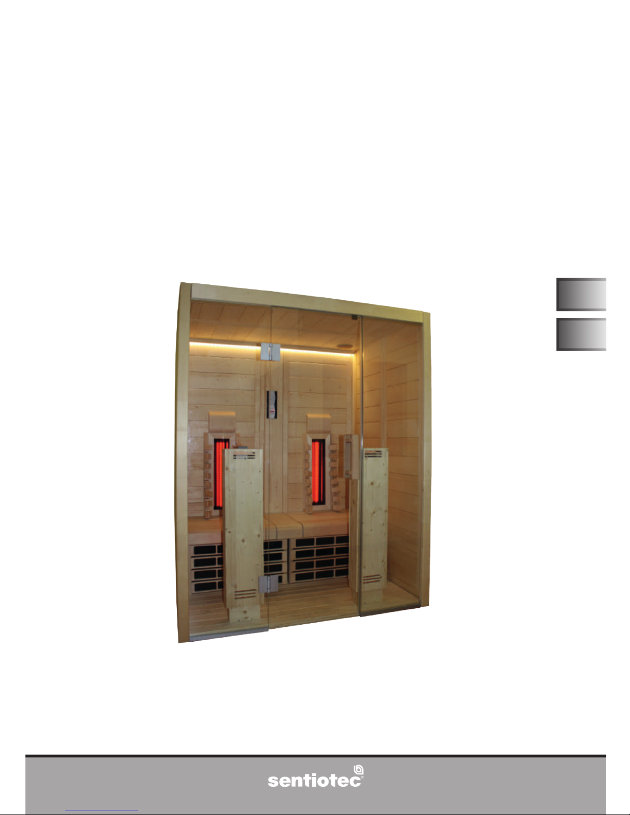
Infrarotkabine
VitaMy 164
164 x 120 x 202 cm
VITAMY-164-B / 1-037-765: VitaMy 164 Basic
VITAMY-164-BT / 1-037-767: VitaMy 164 BT
VITAMY-164-S&L / 1-037-768: VitaMy 164 S&L
Symbolfoto

WORLD OF WELLNESS
Inhaltsverzeichnis
1. Zu dieser Anleitung 3
2. Wichtige Hinweise zu Ihrer Sicherheit 4
2.1. Bestimmungsgemäßer Gebrauch 4
2.2. Sicherheitshinweise 4
3. Produktbeschreibung 6
3.1. Lieferumfang VitaMy 164 Basic 6
3.2. Lieferumfang VitaMy 164 BT 6
3.3. Lieferumfang VitaMy 164 S&L 6
3.4. Produktfunktionen 7
4. Montage der Infrarotkabine VitaMy 164 8
4.1. Benötigtes Werkzeug 8
4.2. Stückliste Infrarotkabine VitaMy 164 Basic / BT / S&L 8
4.3. Montage der Kabine 10
4.4. Einbau der Infrarot-Steuerung 33
4.5. Einbau des Bluetooth Moduls (nur VitaMy 164 BT) 36
4.6. Einbau der sound & light (nur VitaMy 164 S&L) 38
4.7. Montage der Bank 39
4.8. Montage der Abstandleisten der Rückwand 40
4.9. Montage der Rückenlehnen und Kopfstützen 40
5. Reinigung und Wartung 42
5.1. Reinigung 42
5.2. Wartung 42
6. Problemlösung 42
7. Entsorgung 42
8. Technische Daten 43
9. Grundriss 43
WORLD OF WELLNESS
DE
Montage- und Gebrauchsanweisung S. 3/44
1. Zu dieser Anleitung
Lesen Sie diese Montage- und Gebrauchsanweisung gut durch und bewahren
Sie sie in der Nähe der Infrarotkabine auf. So können Sie jederzeit Informationen
zu Ihrer Sicherheit und zur Bedienung nachlesen.
Symbole in Warnhinweisen
In dieser Montage- und Gebrauchsanweisung ist vor Tätigkeiten, von denen eine
Gefahr ausgeht, ein Warnhinweis angebracht. Befolgen Sie diese Warnhinweise
unbedingt. So vermeiden Sie Sachschäden und Verletzungen, die im schlimmsten
Fall sogar tödlich sein können.
In den Warnhinweisen werden Signalwörter verwendet, die folgende Bedeutungen haben:
GEFAHR!
Wenn Sie diesen Warnhinweis nicht beachten, sind Tod oder schwere
Verletzungen die Folge.
WARNUNG!
Wenn Sie diesen Warnhinweis nicht beachten, können Tod oder schwere
Verletzungen die Folge sein.
VORSICHT!
Wenn Sie diesen Warnhinweis nicht befolgen, können leichte Verletzungen die Folge sein.
ACHTUNG!
Dieses Signalwort warnt Sie vor Sachschäden.
Andere Symbole
Dieses Symbol kennzeichnet Tipps und nützliche Hinweise.
Sie nden diese Montage- und Gebrauchsanweisung auch im Download-
bereich unserer Webseite auf www.sentiotec.com/downloads.

WORLD OF WELLNESS
Montage- und Gebrauchsanweisung S. 4/44
2. Wichtige Hinweise zu Ihrer Sicherheit
Die Infrarotkabine ist nach anerkannten sicherheitstechnischen
Regeln gebaut. Dennoch können bei der Verwendung Gefahren
entstehen. Befolgen Sie deshalb die folgenden Sicherheitshinweise
und die speziellen Warnhinweise in den einzelnen Kapiteln.
2.1. Bestimmungsgemäßer Gebrauch
Die Infarotkabine dient zur Erwärmung des menschlichen Körpers.
Der Standort der Kabine muss vor Spritzwasser geschützt sein.
Für einen optimalen Betrieb sollte der Standort eine Umgebungstemperatur von mindesten 20 °C aufweisen. Die maximale Umgebungsluftfeuchte sollte 95% nicht überschreiten.
Die Kabine muss auf einer ebenen Fläche aufgestellt werden.
Jeder darüber hinausgehende Gebrauch gilt als nicht bestimmungsgemäß. Nicht bestimmungsgemäßer Gebrauch kann zur Beschädigung des Produkts, zu schweren Verletzungen oder Tod führen.
2.2. Sicherheitshinweise
● Montage- und Anschlussarbeiten an elektrischen Teilen (Steue-
rung, Strahler,...) dürfen nur im spannungsfreien Zustand durchgeführt werden.
● Beachten Sie auch die örtlichen Bestimmungen am Aufstellort.
● Bei Problemen, die in den Montageanweisungen nicht ausführ-
lich genug behandelt werden, wenden Sie sich zu Ihrer eigenen
Sicherheit an Ihren Lieferanten.

WORLD OF WELLNESS
DE
Montage- und Gebrauchsanweisung S. 5/44
● Die Kabine darf nicht von Kindern unter 8 Jahren verwendet
werden.
● Die Kabine darf von Kindern über 8 Jahren, von Personen mit
verringerten psychischen, sensorischen oder mentalen Fähigkeiten und von Personen mit Mangel an Erfahrung und Wissen
unter folgenden Bedingungen verwendet werden:
– wenn sie beaufsichtigt werden.
– wenn ihnen die sichere Verwendung gezeigt wurde und sie
die Gefahren, die entstehen können, verstehen.
● Kinder dürfen nicht mit der Kabine spielen.
● Kinder unter 14 Jahren dürfen die Kabine nur reinigen, wenn sie
beaufsichtigt werden.
● Die Kabine darf nicht mit Dampfreinigern, Hochdruckreinigern
oder Spritzwasser gereinigt werden.
● Wenn Sie unter dem Einuss von Alkohol, Medikamenten oder
Drogen stehen, verzichten Sie aus gesundheitlichen Gründen
auf das Saunabad.
● Stellen Sie sicher, dass keine brennbaren Gegenstände auf den
Heizelementen liegen, bevor Sie die Steuerung einschalten.

WORLD OF WELLNESS
Montage- und Gebrauchsanweisung S. 6/44
3. Produktbeschreibung
3.1. Lieferumfang VitaMy 164 Basic
● 1x Infrarotkabine VitaMy 164
● 1x 1-037-357 / Leistungsteil wave.com4 Infra
● 1x 1-012-222 / Bedienteil wave.com4 Infra
● 1x 1-009-265 / Netzanschlussleitung Infrarot 2,5m
● 2x 1-028-862 / Kabel GST18i/3s – GST18i/3B 0,5m
● 2x 1-028-731 / Verteiler T-Form (3polig) IR-1P2
● 2x 1-027-788 / Infrarotstrahler ECO 500 - dunkel (vormontiert)-Frontstrahler
● 2x 1-027-785 / Infrarotstrahler ECO 350 - dunkel - Rückenstrahler
● 2x 1-028-348 / IR- Wärmeplatte 380mm x 700mm, 230V/100W (vormontiert)
● 2x 1-037-397 / Schalter-Set IR-Wärmeplatte (vormontiert)
● 1x 1-037-396 / LED Strip & Netzteil
● 1x 1-028-660 / Entlüftung Rund Espe 631-A
● 2x 1-028-629 / Specksteinschale
3.2. Lieferumfang VitaMy 164 BT
zusätzlich zu VitaMy 164 Basic
● 1x 1-016-290 / wave.com4 bluetooth
● 1x 1-017-094 / Körperschallwandler „Exciter“
3.3. Lieferumfang VitaMy 164 S&L
zusätzlich zu VitaMy 164 Basic
● 1x 1-028-257 / sound & light Set (Farblampe, Leistungsteil, Bedienteil, USB-
Dock)
WORLD OF WELLNESS
DE
Montage- und Gebrauchsanweisung S. 7/44
3.4. Produktfunktionen
Infrarotkabine
Massivkabine aus Fichtenholz für die Infrarotbestrahlung von 2 Personen.
Harzgallen sind kein Reklamationsgrund. Da in Fichtenholz immer wieder
Harzgallen vorkommen und man beim Aussortieren nicht erkennen kann
in welcher Tiefe diese sich benden.
Wenn diese knapp unter der Oberäche sind brechen sie bei Hitzeent-
wicklung auf und „bluten“ aus.
Das Ausgelaufene Harz kann man mit einem Aceton gedrängtem Lappen
entfernen. Wenn lediglich Harztropfen entstehen, lassen Sie diese aushärten und schaben sie anschließend mit einem Messer vorsichtig ab.
Infrarotsteuerung wave.com4 Infra
Steuerung zum Dimmen von 2 Heizkreisen mit je maximal 1,5 kW und zum
Dimmen von Licht und einem optionalen Lüfter.
wave.com4 bluetooth (nur Ausführung VitaMy 164 BT)
Das Bluetooth-Modul wave.com4 sound ermöglicht, Musik in der Sauna oder in der
Infrarotkabine abzuspielen. Die Musik wird dabei über eine Bluetooth-Verbindung
von einem bluetooth-fähigem Gerät (=Audio-Quelle) auf das Bluetooth-Modul
übertragen. Als Audio-Quelle können alle bluetooth-fähigen Geräte, wie die meisten Mobiltelefone, Tablets, Notebooks etc., verwendet werden. Der Verstärker
ist im Bluetooth-Modul bereits integriert.
sound & light Farblampe (nur Ausführung VitaMy 164 S&L)
Die Farblampe sound & light ermöglicht das Abspielen von Musik mittels USBStick und Beleuchtung der Kabinen mit verschiedensten Farben.
Das Farblicht kann manuell ausgewählt oder verschiedene Farben im Automatikbetrieb abgespielt werden.

WORLD OF WELLNESS
Montage- und Gebrauchsanweisung S. 8/44
4. Montage der Infrarotkabine VitaMy 164
Kontrollieren Sie, bevor Sie mit der Arbeit beginnen, anhand der Stückliste, ob
alle Einzelteile auch tatsächlich mitgeliefert wurden. Sollten Einzelteile ausnahmsweise fehlen, benachrichtigen Sie spätestens 14 Tage nach Erhalt der
Kabine Ihren Händler.
Für die Montage benötigen Sie einen Helfer!
Weiters empfehlen wir die Löcher für die Schrauben vorzubohren.
4.1. Benötigtes Werkzeug
● Hammer und Beilageholz oder einen Gummihammer
● Akkuschrauber mit Bits für Kreuzschrauben und Torx
● Rollmaßband
● Wasserwaage
● Durchschlag oder Holzklötzchen 12 mm
● Imbus 1,5 mm
4.2. Stückliste Infrarotkabine VitaMy 164 Basic / BT / S&L
Stückliste -VitaMy
1-037-804 1 Bodenrahmen hinten - 1640 x 40 x 90 mm
1-037-808 1 Bodenrahmen links - 1140 x 40 x 90 mm
1-037-810 1 Bodenrahmen rechts - 1140 x 40 x 90 mm
1-037-769 1 Wandelement W1 - 1930 x 540 x 40 mm
1-037-770 1 Wandelement W2 - 1930 x 540 x 40 mm
1-037-772 1 Wandelement W3 rechts mit Ausschnitt - 1930 x 657 x 40 mm
1-037-773 1 Wandelement W4 links mit Ausschnitt - 1930 x 657 x 40 mm
1-037-770 1 Wandelement W5 - 1930 x 540 x 40 mm
1-037-769 1 Wandelement W6 - 1930 x 540 x 40 mm
1 Elektroelement je nach Type (siehe Ende Stückliste)
1-037-794 2 Ecksteher Multiklipp - 1930 x 60 x 60 mm
1-037-797 1 Ecksteher Multiklipp links vorne - 2020 x 60 x 60 mm
1-037-798 1 Ecksteher Multiklipp rechts vorne - 2020 x 60 x 60 mm

WORLD OF WELLNESS
DE
Montage- und Gebrauchsanweisung S. 9/44
Stückliste -VitaMy
1-037-804 1 Bodenrahmen hinten - 1640 x 40 x 90 mm
1-037-808 1 Bodenrahmen links - 1140 x 40 x 90 mm
1-037-810 1 Bodenrahmen rechts - 1140 x 40 x 90 mm
1-037-769 1 Wandelement W1 - 1930 x 540 x 40 mm
1-037-770 1 Wandelement W2 - 1930 x 540 x 40 mm
1-037-772 1 Wandelement W3 rechts mit Ausschnitt - 1930 x 657 x 40 mm
1-037-773 1 Wandelement W4 links mit Ausschnitt - 1930 x 657 x 40 mm
1-037-770 1 Wandelement W5 - 1930 x 540 x 40 mm
1-037-769 1 Wandelement W6 - 1930 x 540 x 40 mm
1 Elektroelement je nach Type (siehe Ende Stückliste)
1-037-794 2 Ecksteher Multiklipp - 1930 x 60 x 60 mm
1-037-797 1 Ecksteher Multiklipp links vorne - 2020 x 60 x 60 mm
1-037-798 1 Ecksteher Multiklipp rechts vorne - 2020 x 60 x 60 mm
1-037-788 1 Massivleiste über Glasfront - 1520 x 101 x 40 mm
1-037-998 1 Dachauflageleiste - 1560 x 40 x 40 mm
1-039-369 1 Dachauflageleiste - 1560 x 40 x 40 mm mit Bohrung
1-037-999 2 Dachauflageleiste - 1120 x 40 x 40 mm
1-037-819 1 Dachelement vorne - 1520 x 540 x 40 mm
1-037-820 1 Dachelement hinten mit Lüfterausschnitt - 1520 x 540 x 40 mm
1-032-843 1 ESG Glas klar ohne Loch - 1945 x 474 x 8 mm
1-032-844 1 ESG Glas klar für Türbänder G/G 8652-02 - 1945 x 474 x 8mm
1-032-822 1 ESG Glastür klar für Türbänder G/G8652-02 - 1915 x 590 x 8mm
1-039-376 2 Alu U-Profile - L = 460 mm
1-039-382 1 Glastürdichtung - L = 1915 mm
1-039-382 1 Türgriff- Set VitaMy 164
1-038-058 1 Boden Fichte - 1554 x 640 mm
1-038-036 1 Strahlerkasten Fichte links - 1050 x 230 x 120 mm
1-038-046 1 Strahlerkasten Fichte rechts - 1050 x 230 x 120 mm
1-038-001 1 U-Leisten für IR-Wärmeplatte links - 410 x 60 x 65 mm
1-038-003 1 U-Leisten für IR-Wärmeplatte rechts - 410 x 60 x 65 mm
1-038-020 2 IR-Wärmeplatte VitaMy 164 - 738 x 420 x 43 mm
1-038-004 1 Aussteifungsleiste für Wärmeplatten - 1560 x 40 x 25 mm
1-038-031 1 Bankauflage links - 460 x 410 x 40 mm
1-038-032 1 Bankauflage rechts - 460 x 410 x 40 mm
1-039-371 1 Bankauflage Leiste - 300 X 40 X 40 mm
1-038-017 1 Bank VitaMy 164 - 1560 x 560 x 100 mm
1-038-029 1 LED Abdeckleiste - 1560 x 30 x 30 mm
1-038-054 2 Rahmen für Strahler 350W Linde - 735 x 230 x 20 mm
1-038-030 4 Ergo- Rückenlehne
1-038-282 2 Kopfstütze VitaMy 164
1-038-027 2 Abstandleiste Rückwand - 2020 x 40 x 50 mm
1-038-061 1 Montagematerial
1-038-133 1 Montageanleitung
Elektroelement VitaMy 164 Basic
1-037-783 1 Elektroelement - 1930 x 206 x 40 mm - 2 Ausschnitte
Elektroelement VitaMy 164 BT
1-039-373
1 Elektroelement - 1930 x 206 x 40 mm - 3 Ausschnitte
Elektroelement VitaMy 164 S&L
1-037-784 1 Elektroelement - 1930 x 206 x 40 mm - 4 Ausschnitte
WORLD OF WELLNESS
Montage- und Gebrauchsanweisung S. 10/44
4.3. Montage der Kabine
Beachten Sie den Grundriss auf Seite 43.
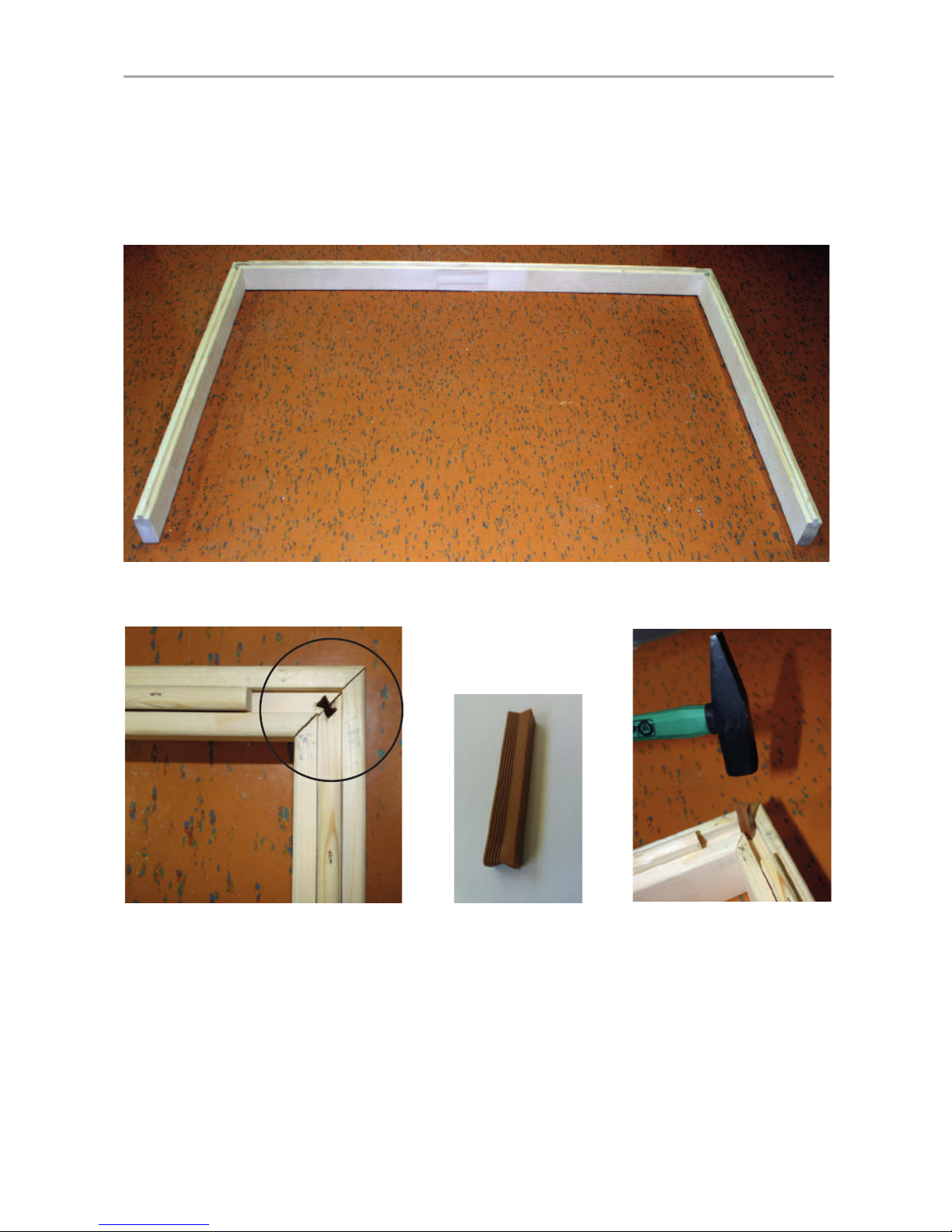
Montage des Bodenrahmens
Abb. 1: Auegen der drei Bodenrahmen-Elemente
Abb. 2: Bodenelemente verbinden
Schlagen Sie die Kunstoffschwalben vorsichtig mit einem Hammer, an den beiden
Ecken des Bodenrahmens ein, bis diese bündig mit der Nut des Elements sind.
Verwenden Sie einen Durchschlag oder ein Holzklötzchen, damit die Kunststoffschwalbe gut versenkbar ist.
WORLD OF WELLNESS
DE
Montage- und Gebrauchsanweisung S. 11/44
Montage der Wandelemente
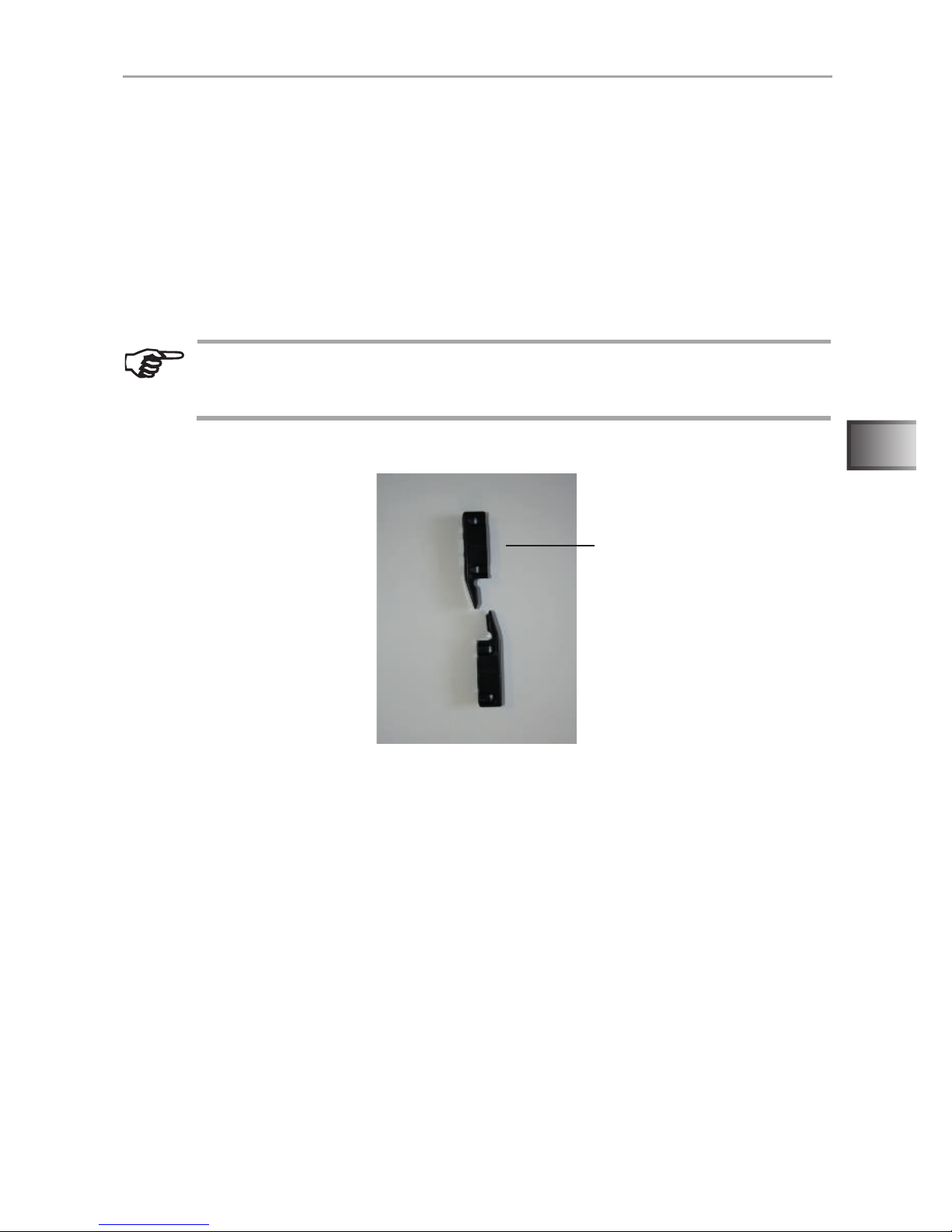
Beginnen Sie die Montage der Wandelemente mit den Wandelementen W2 und
W3 bzw. W4 und W5 (siehe Kapitel Grundriss auf Seite 43). Die Wandelemente
werden mit den „Multiclips“ mit den Eckstehern verbunden.
Achten Sie darauf, dass die Elemente mit der Öffnung für den Infrarotstrahler
W3 u. W4 an der Rückseite der Kabine verwendet werden. Die Unterkante des
IR-Straher-Ausschnitts ist in einer Höhe von 64 cm, die Abschrägung zeigt nach
außen.
Abb. 3: Multiclips
Ecksteher
Montieren Sie die Wandelemente mit den Eckstehern am Boden vor und
setzen Sie diese Ecken dann auf den Bodenrahmen auf (siehe Abb. 5,
Abb.6 und Abb.7)
WORLD OF WELLNESS
Montage- und Gebrauchsanweisung S. 12/44
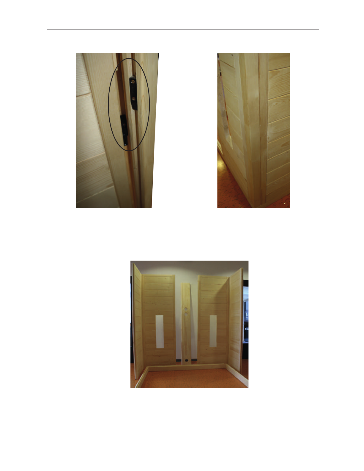
Abb. 4: Wandelemente mit Ecksteher verbinden
Stecken Sie den Ecksteher von oben nach unten auf die Wandelemente. Achten Sie dabei auf die korrekte Ausrichtung der „Multiclips“ (siehe Abb. 4). Der
Ecksteher muss bündig mit den Wandelementen sein.
Abb. 5: Montage auf Bodenrahmen
Eine vormontierte Ecke auf den Bodenrahmen stellen, diese ist lose mit Nut und
Feder verbunden.
WORLD OF WELLNESS
DE
Montage- und Gebrauchsanweisung S. 13/44
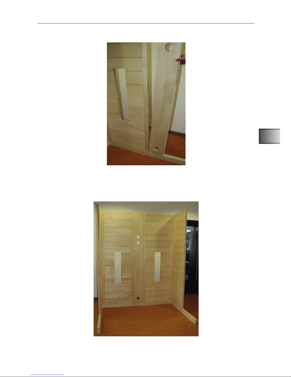
Abb. 6: Elektroelement einsetzen
Abb. 7: Fertig montierte Rückwand
Nachdem Sie das Elektroelement eingesetzt haben, fahren Sie mit der zweiten
Ecke fort.
WORLD OF WELLNESS
Montage- und Gebrauchsanweisung S. 14/44
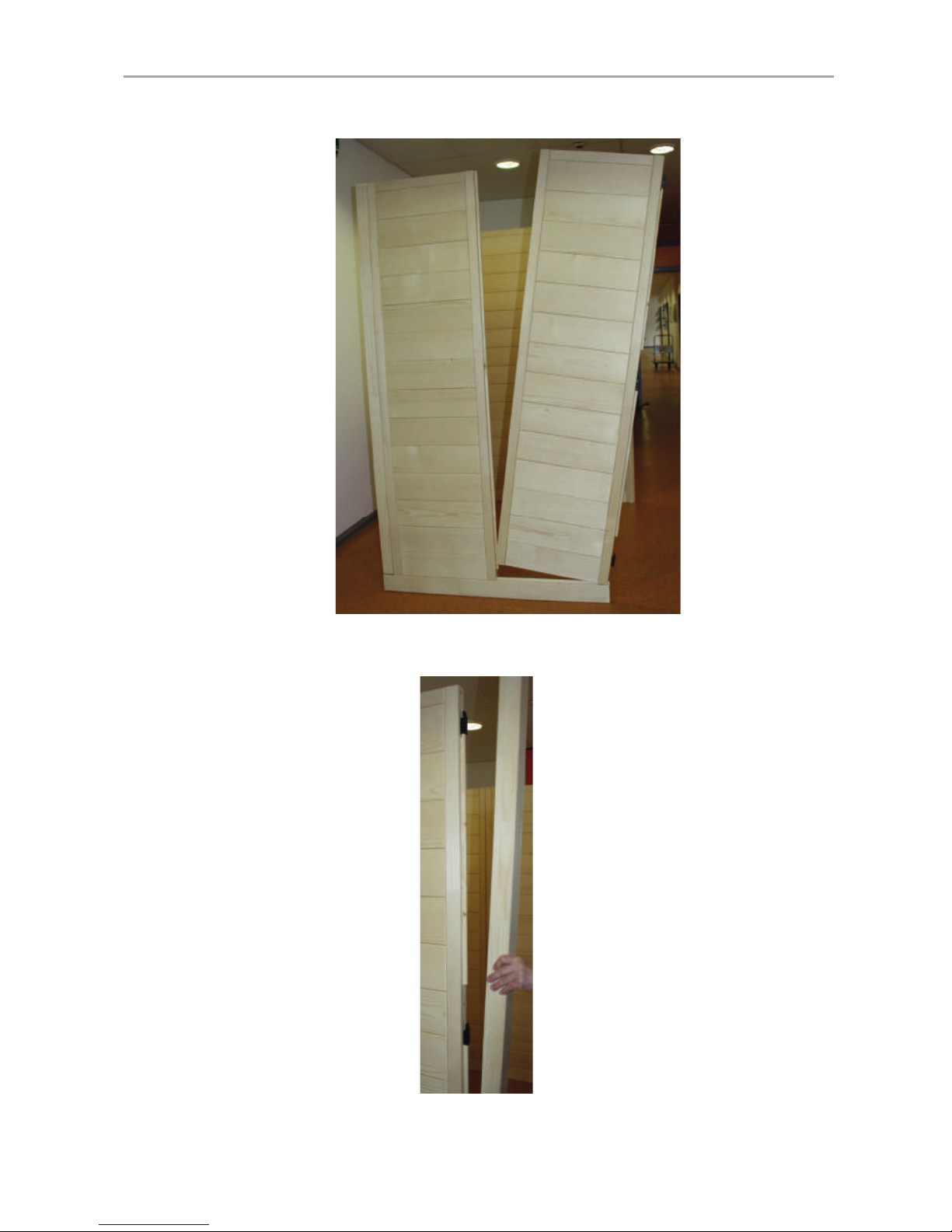
Abb. 8: Montage seitliche Wandelemente W1 und W6
Abb. 9: Montage der beiden vorderen Ecksteher mit Nut für Glas
WORLD OF WELLNESS
DE
Montage- und Gebrauchsanweisung S. 15/44
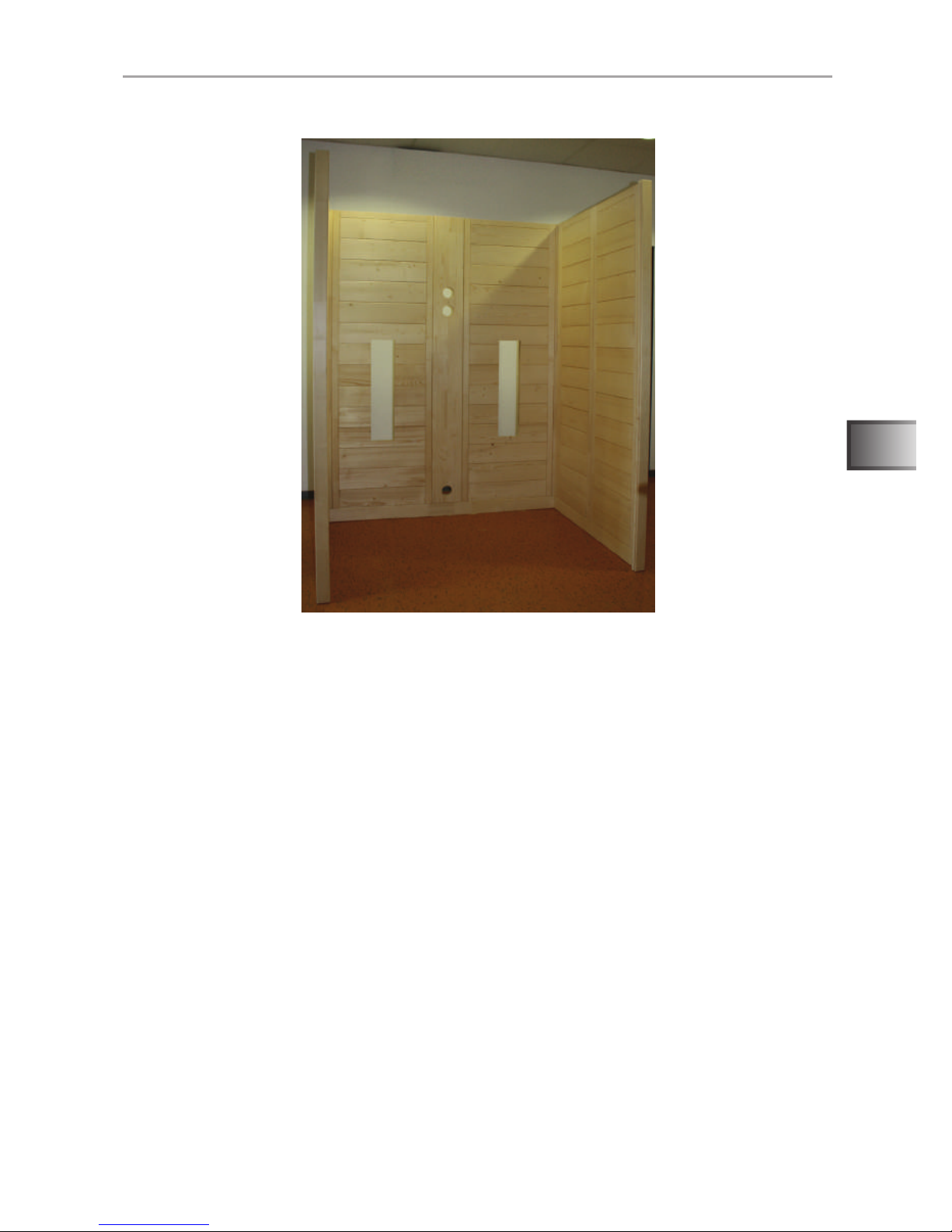
Abb. 10: Montierte Wandelemente
WORLD OF WELLNESS
Montage- und Gebrauchsanweisung S. 16/44
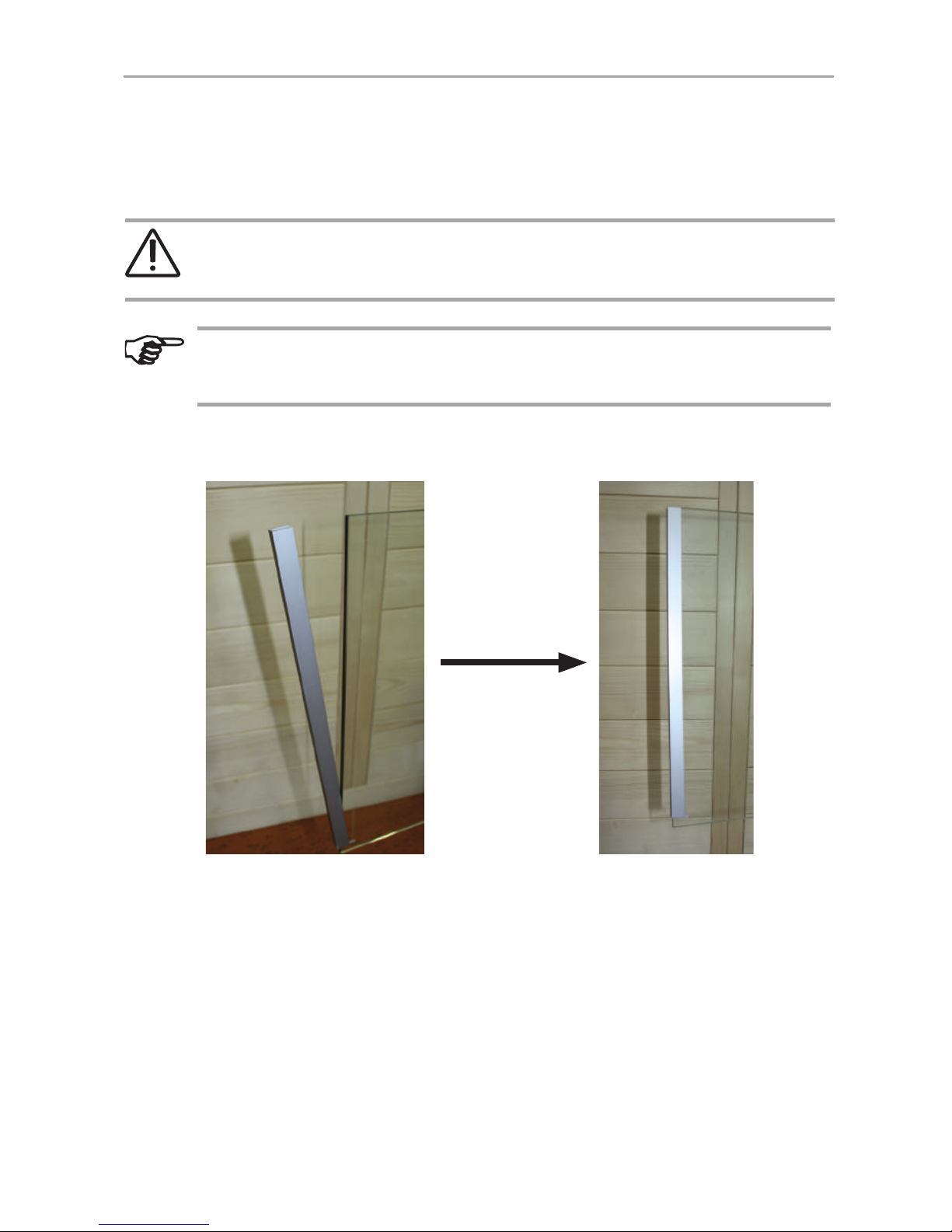
Abb. 11: U-Prole an den Glasplatten anbringen
Stecken Sie das U-Prol bündig auf die Glasplatte. Achten Sie dabei auf den bündigen Abschluss der Prole mit dem Glas an jener Seite, an der die Tür sein wird.
WARNUNG!
Kleben Sie nachdem die Kabine korrekt positioniert ist, die U-Prole mit
Silikon oder Montagekleber an den Boden.
Sie können bei der Montage der beiden Glasplatten entscheiden, ob die
Türe rechts oder links angeschlagen sein soll. Achten Sie dazu auf das
Glas mit den Bohrungen für die Beschläge der Tür.
Montage der Glaselemente
WORLD OF WELLNESS
DE
Montage- und Gebrauchsanweisung S. 17/44
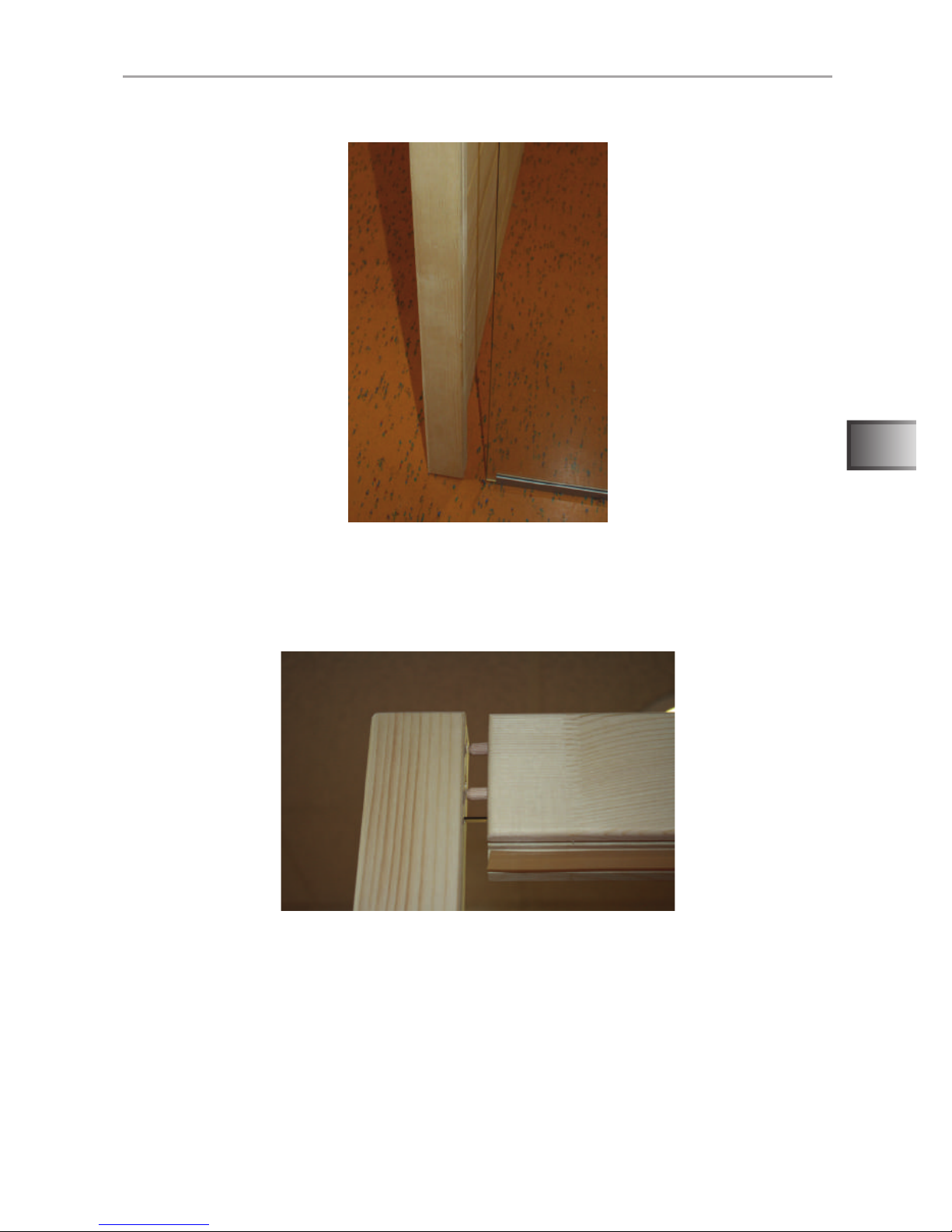
Abb. 12: Einsetzen der Glasscheibe in die Nut des Eckstehers
Schieben Sie das Glas vorsichtig in die Nut des Eckstehers. Führen Sie dies für
beide Glas-Seitenteile durch.
Abb. 13: Montage Massivleiste über der Glasfront
Für die Montage der Massivleiste die beiden vorderen Ecksteher nach außen
drücken und die Massivleiste mittles Dübelverbindungen einsetzen.
Achten Sie dabei auf die Glas-Seitenteile, dass diese gut in der Nut des Eckstehers bleiben.
WORLD OF WELLNESS
Montage- und Gebrauchsanweisung S. 18/44
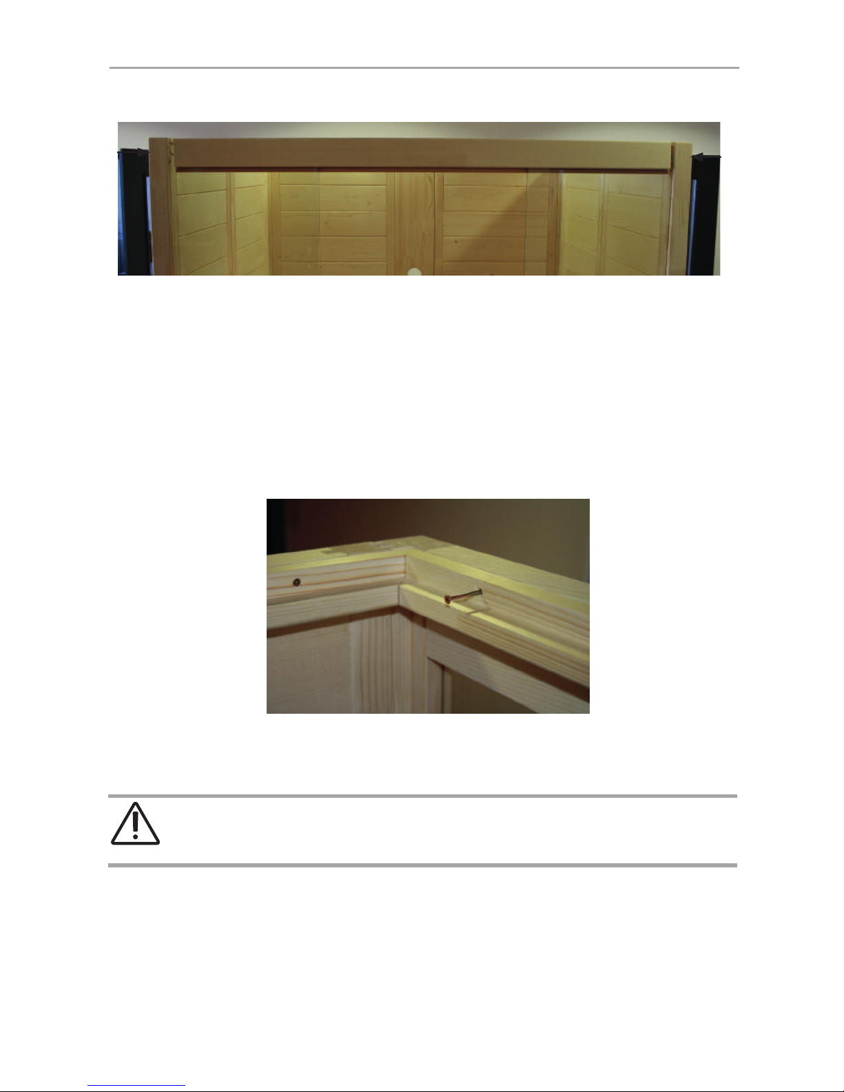
Abb. 14: Montage Dachauageleisten
Die Massivleiste durch zusammendrücken der seitlichen Wandelemente xieren,
bis die Dübel nicht mehr sichtbar sind.
Schrauben Sie die Dachauflageleisten wie in Abb. 14 und Abb. 15 an allen
Wänden der Kabine fest. Achten Sie dabei auf einen bündigen Abschluss von
Wandelementen und Dachauageleiste.
WARNUNG!
Achten Sie darauf, dass jede Auageleiste fest verschraubt ist und alle
Schrauben verwendet wurden.
Montage der Dachelemente
Schrauben
14 Stk: 3,5 x 50
Kontrollieren Sie die rechtwinkelige Ausrichtung der Kabine in den Ecken oder
messen mit dem Rollband die beiden Diagonalen der Kabine, wenn diese gleich
lang sind, ist die Kabine korrekt ausgerichtet.
Abb. 15: Fixieren der Massivleiste
WORLD OF WELLNESS
DE
Montage- und Gebrauchsanweisung S. 19/44
Abb. 16: Dachauageleisten
Abb. 17: Einlegen Dachelement hinten mit Lüfterausschnitt
Abb. 18: Einlegen Dachelemente vorne
WORLD OF WELLNESS
Montage- und Gebrauchsanweisung S. 20/44
Abb. 19: Befestigen der Dachelemente
Abb. 20: Aufsetzen der Türdichtung
Die Dichtung wird auf das Glaselement aufgesetzt, welches keine Bohrungen
für die Türbeschläge besitzt. Achten Sie darauf, dass der Anschlag der Dichtung
innen ist.
Montage der Türe
Schrauben
14 Stk: 3,5 x 35
Nachdem die Dachelemente eingelegt wurden, müssen diese mit der Dachauflageleiste verschraubt werden.
WORLD OF WELLNESS
DE
Montage- und Gebrauchsanweisung S. 21/44
Setzen Sie zuerst die beiden Silikoneinlagen in die Bohrungen für den Türgriff
am Glaselement ein. Danach verschrauben Sie die beiden Griffe vorsichtig
miteinander.
Abb. 21: Montage Türgriff
Schrauben
2 Stk: 3,5 x 70
Die untere Bohrung des Türgriffs ist in 92,5 cm Höhe. Die Türgriffe werden von
außen miteinander verschraubt.
WORLD OF WELLNESS
Montage- und Gebrauchsanweisung S. 22/44
Abb. 22: Montage Türbeschläge 1
Schrauben Sie die beiden Türbeschläge am Fix-Glaselement fest, achten sie
dabei auf die gerade Ausrichtung der Beschläge und darauf, dass die Öffnung
der Türe nach außen erfolgt.
Die Ausrichtung der Beschläge wird durch die Justierung / Drehung der
beiden Kunstoffringe vorgenommen.
Abb. 23: Montage Türbeschläge 2
Führen Sie die Schritte aus Abb. 22 und Abb. 23 nochmals aus, um das Türblatt
mit dem Fix-Glaselement zu verbinden.
Setzen Sie abschließend die Blenden auf und xieren Sie diese durch anziehen
der Inbusschraube.
WORLD OF WELLNESS
DE
Montage- und Gebrauchsanweisung S. 23/44
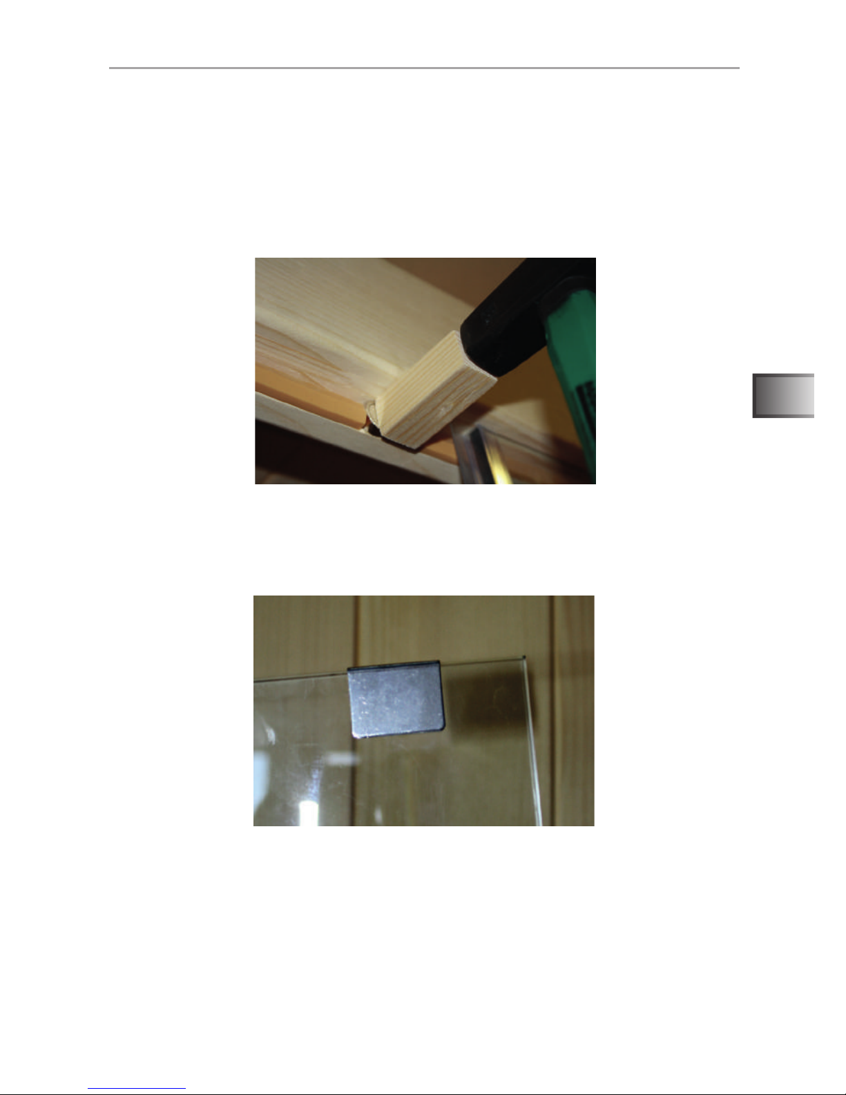
Abb. 24: Montage Türmagnet
Der Magnet für die Tür muss auf jener Seite sein, an der die Türe öffnet.
Montieren Sie den Magnet ggfs. auf die entsprechende Seite.
Schneiden Sie die Türdichtung über der Ausnehmung für den Magnet mit
einem scharfen Messer durch und legen die Ausnehmung frei. Schlagen Sie
den Türmagnet mit Hilfe eines Holzklötzchens mit dem Hammer in die Ausnehmung. Passen Sie die Länge der Dichtung bis zum Magnet an.
Abb. 25: Montage Überschub-Blech
Schieben Sie das Überschub-Blech an jener Stelle über die Glastüre, an der
sich der Magnet auf die Massivleiste bendet.
WORLD OF WELLNESS
Montage- und Gebrauchsanweisung S. 24/44
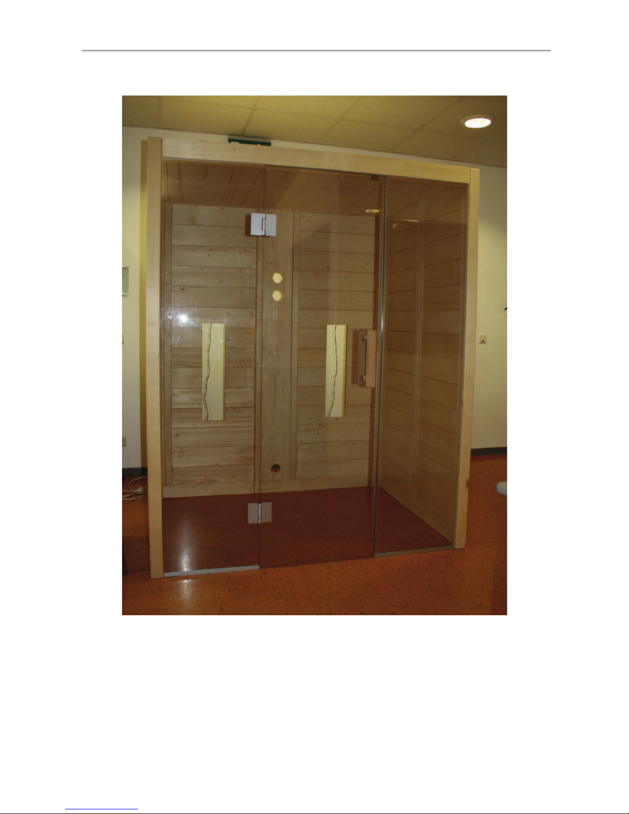
Abb. 26: Fertige Kabinenwände und Dachelemente
Abb. 27: Befestigung für Kabinenboden montieren
Montage des Kabinenbodens

WORLD OF WELLNESS
DE
Montage- und Gebrauchsanweisung S. 25/44
Abb. 28: Kabinenboden einlegen
Montage der Frontstrahler
Abb. 29: Frontstrahler xieren
Achten Sie darauf, dass die Kabel der Frontstrahler frei am Boden liegen
und nicht durch den Kabinenboden eingeklemmt oder beschädigt werden.
WORLD OF WELLNESS
Montage- und Gebrauchsanweisung S. 26/44
Abb. 30: Fronstrahler xieren
Nachdem die Strahler am Boden eingerastet sind, xieren Sie diese jeweils mit
einer Drehung um 90° an den Imbusschrauben im Uhrzeigersinn an den vier
Befestigungspunkten.
Abb. 31: Einlegen der Specksteinschalen
WORLD OF WELLNESS
DE
Montage- und Gebrauchsanweisung S. 27/44
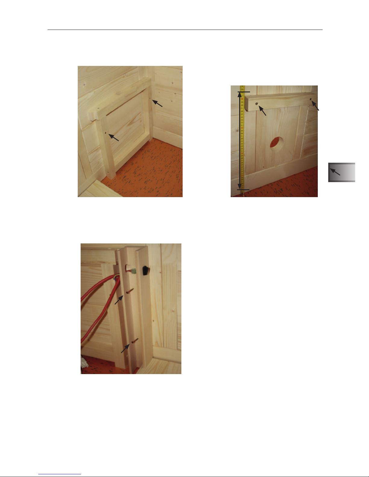
Abb. 32: Montage der Bankauage
Schrauben Sie links und rechts in der Kabine die Bankauagen und am Elektroelement die Bankauage-Leiste mit je 2 Schrauben fest.
Abb. 33: Montage der U-Leisten für Wärmeplatten
Schrauben Sie links und rechts in der Kabine die U-Leisten für Wärmeplatten mit
je 2 Schrauben fest. Achten Sie darauf, dass die Schalter oben angeordnet sind.
Montage der Bankauage und der IR-Wärmeplatten
Schrauben
6 Stk: 5 x 70
41 cm
Schrauben
4 Stk: 3,5 x 50

WORLD OF WELLNESS
Montage- und Gebrauchsanweisung S. 28/44
Abb. 34: Einsetzen der IR-Wärmeplatte VitaMy 164
Setzen Sie die den beide IR-Wärmeplatten VitaMy 164 in die U-Leisten ein. Die
Ausnehmung dient zur Durchführung der Leitung des Frontstrahles (siehe Abb. 35)
Achten Sie beim Einsetzen der IR-Wärmeplatte auf die Kabel der Schalter,
diese dürfen nicht eingeklemmt oder beschädigt werden.
Abb. 35: Einsetzen der Aussteifungsleiste für IR-Wärmeplatten VitaMy
Legen Sie die Aussteifungsleiste für Wärmeplatten von innen auf den Boden.
Verschrauben Sie die Leiste mit dem Rahmen der Wärmeplatten. Die Ausnehmung dient zur Durchführung der Leitung des Frontstrahles.
Schrauben
2 Stk: 3,5 x 50

WORLD OF WELLNESS
DE
Montage- und Gebrauchsanweisung S. 29/44
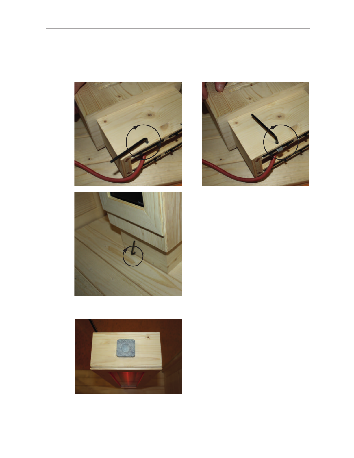
Abb. 36: Montage der Entlüftung
Schrauben Sie das Basiselement der Entlüftung mit den 3 beiliegend Schrauben
fest.
Schrauben Sie anschließend das Holzteller ein und sichern Sie die Schraube
von außen mit der Kunststoffkappe.
Montage der Entlüftung

WORLD OF WELLNESS
Montage- und Gebrauchsanweisung S. 30/44
Abb. 37: Montage der LED-Abdeckleiste
Schrauben Sie die LED-Abdeckleiste mit 3 Schrauben von außen an der Decke
fest.
Abb. 38: Einkleben des LED Stripes
Kleben Sie den LED Stripe in die Abdeckleiste ein. Der Stecker der LED Stripes
muss genügend weit durch die Öffnung in der Decke reichen (siehe Abb. 39)
Montage der LED Abdeckleiste
Schrauben
3 Stk: 3,5 x 50

WORLD OF WELLNESS
DE
Montage- und Gebrauchsanweisung S. 31/44
Abb. 39: Verbinden des LED Stripes mit der Steuerung
Geben Sie das Netzteil der LED Beleuchtung unter die Bank. Führen Sie die
Anschlussleitung und den Netzstecker durch die Öffnung in der Rückwand nach
außen.
Achten Sie beim Anschluss des LED Stripes auf den Pfeil am Stecker.
Dieser muss beim Stripe an der Seite mit dem Aufdruck „+12V“ sein.
Der Netzstecker der LED Beleuchtung muss sich außerhalb der Kabine
benden.
Anschluss des LED Stripes
Abb. 40: Einlegen der Sitzbank
Legen Sie die Bank auf die Auageleisten.

WORLD OF WELLNESS
Montage- und Gebrauchsanweisung S. 32/44
Abb. 41: Rückenstrahler (Infrarot-Strahler ECO 350) montieren
Setzten Sie die beiden Strahler von innen in den Ausschnitt ein. Schrauben Sie
die Strahler mit je 4 Schrauben fest.
VORSICHT!
Achten Sie darauf, dass der Anschlusskasten der Strahler auf der
Oberseite ist!
Montage der Rückenstrahler
Schrauben
8 Stk: 3 x 18
Abb. 42: Blende der Rückenstrahler montieren
Schrauben Sie die Holzblenden der Strahler jeweils mit 4 Schrauben von der
Rückseite der Kabine aus fest (Bohrungen vorhanden).
Schrauben
8 Stk: 3,5 x 50

WORLD OF WELLNESS
DE
Montage- und Gebrauchsanweisung S. 33/44
4.4. Einbau der Infrarot-Steuerung
Montieren Sie das Bedienteil an die vorgesehene Stelle in der Rückwand der
Kabine.
Beachten Sie für die Montage, Inbetriebnahme und Bedienung die Anleitung welche der Steuerung beiliegt.
Die Betriebsart „Raumtemperaturregelung“ wird von der beiliegenden
Steuerung nicht unterstützt.
Montage des Bedienteils
Abb. 43: Montage des Bedienteils
Stellen Sie für die Montage der Steuerung die Sitzbank auf.
wave.com4
Infra

WORLD OF WELLNESS
Montage- und Gebrauchsanweisung S. 34/44
Das Leistungsteil der Steuerung wird unter der Bank der Kabine platziert und
wie folgt angeschlossen.
Anschluss des Leistungsteils
Abb. 44: Anschlüsse Leistungsteil
Stecker Beschreibung
1 wave.com4 Infra Bedienteil
7 IR-Heizgruppe 1
8 IR-Heizgruppe 2
9 Netzanschluss
10 Lüfteranschluss (schwarz) - optional
11 Lichtanschluss (grün)

WORLD OF WELLNESS
DE
Montage- und Gebrauchsanweisung S. 35/44
Das Leistungsteil der Steuerung wird unter der Bank der Kabine platziert und
wie folgt angeschlossen.
Heizgruppe 1: Frontstahler links, Rückenstrahler links, Wadenstrahler links (über
Schalter)
Heizgruppe 2: Frontstahler rechts, Rückenstrahler rechts, Wadenstrahler rechts
(über Schalter)
Die Anordnung kann beinahe beliebig den eigenen Wünschen angepasst werden.
Es ist jedoch zu beachten das je Anschluss max. 750 W angeschlossen werden!
Zuordnung der Heizgruppen
Abb. 45: Beispiel für Heizgruppe 1
Rückenstrahler linksWärmeplatte links
Schalter Wärmeplatte
Frontstrahler links
Schalter Wärmeplatte
Verteiler T-Form
Kabel GST18i/3s – GST18i/3B

WORLD OF WELLNESS
Montage- und Gebrauchsanweisung S. 36/44
4.5. Einbau des Bluetooth Moduls (nur VitaMy 164 BT)
Montieren sie das Bedienteil an die vorgesehe Stelle in der Rückwand der Kabine.
Beachten Sie für die Montage, Inbetriebnahme und Bedienung die Anleitung, welche dem Bluetooth-Modul und den Excitern beiliegt.
Montage des Bedienteils
Abb. 46: Montage des Bedienteils
Schrauben Sie die Exciter mit den beiliegenden Schrauben links und rechts im
hinteren Bereich auf die Außenseiter der Kabinendecke.
Montage der Exciter
Abb. 47: Montage der Exciter
wave.com4
bluetooth
wave.com4
Infra

WORLD OF WELLNESS
DE
Montage- und Gebrauchsanweisung S. 37/44
Schließen Sie die Exciter und das Netzteil lt. Anleitung am Bedienteil an. Das
Netzteil muss sich außerhalbe der Kabine benden.
Anschluss des Bedienteils
Abb. 48: Anschluss des Bedienteils

WORLD OF WELLNESS
Montage- und Gebrauchsanweisung S. 38/44
4.6. Einbau der sound & light (nur VitaMy 164 S&L)
Montieren sie das Bedienteil und das USB-Dock an die vorgesehen Stellen in
der Rückwand der Kabine.
Beachten Sie für die Montage, Inbetriebnahme und Bedienung die Anleitung welche der sound & light Farblampe beiliegt.
Montage des Bedienteils und des USB-Docks
Montieren Sie die Farblampe mit den beiliegenden Schrauben in den Deckenausschnitt. Beachten Sie dazu die beiliegende Anleitung „wave.com4 sound&light“.
Abb. 49: Montage Bedienteil
wave.com4
S&L
wave.com4
USB
wave.com4
Infra
Abb. 50: Montage Farblampe
Anschluss der Farblampe

WORLD OF WELLNESS
DE
Montage- und Gebrauchsanweisung S. 39/44
Schließen Sie das Bedienteil, USB-Dock und die Farblampe lt. beiliegender
Anleitung am sound & light Leistungsteil an. Montieren Sie das Leistungsteil
vorzugsweise außen auf der Kabinendecke oder unter der Bank.
Anschluss des Bedienteils und der Farblampe
Abb. 51: Fixieren der Sitzbank
Legen Sie die Bank auf die Auageleisten. Schieben Sie die Sitzächen nach
vorne.
4.7. Montage der Bank
Nachdem die Steuerung fertig angeschlossen ist, kann die Bank fertig montiert
werden.
Schrauben
4 Stk: 4 x 70
VORSICHT!
Sichern Sie die Bank gegen Verrutschen mit den Sicherungsschrauben
an den Bankauagen links, rechts und der Bankauageleiste.

WORLD OF WELLNESS
Montage- und Gebrauchsanweisung S. 40/44
Abb. 53: Montage Rückenlehnen
Schrauben Sie die Abstandleisten an der Rückwand fest, wahlweise bündig oder
bis zu 10 cm nach innen versetzt.
Schrauben
4 Stk: 4 x 70
Schrauben Sie die Multiclips mit Hilfe der Montageschablone mit den beiliegenden Schrauben fest.
Abb. 52: Montage Abstandleisten Rückwand
4.8. Montage der Abstandleisten der Rückwand
4.9. Montage der Rückenlehnen und Kopfstützen

WORLD OF WELLNESS
DE
Montage- und Gebrauchsanweisung S. 41/44
Schrauben Sie die Halterungen mit mindestens 1 cm Abstand zur Oberkante des
Rahmens, seitlich bündig mit der Halterung der Rückenlehnen, fest. Die Höhe
kann je nach Wunsch variiert werden. Stecken Sie anschließend das Kopfelement
an die gewünschte Position.
Abb. 54: Montage Kopfstützen
Entfernen Sie die Montageschablone und stecken Sie abschließend die Rückenlehnen von oben nach unten auf die Halterungen bis diese einrasten.

WORLD OF WELLNESS
Montage- und Gebrauchsanweisung S. 42/44
5. Reinigung und Wartung
5.1. Reinigung
5.2. Wartung
Die Infrarotkabine VitaMy 164 ist wartungsfrei.
6. Problemlösung
● Bei Problemen, die in den Montageanweisungen nicht ausführlich genug
behandelt werden, wenden Sie sich zu Ihrer eigenen Sicherheit an Ihren
Lieferanten.
ACHTUNG!
Schäden an der Kabine
● Übergießen Sie die Kabine und die elektronischen Komponenten nicht mit
Wasser.
● Reinigen Sie die Kabine und die elektronischen Komponenten nicht zu feucht.
● Entsorgen Sie die Verpackungsmaterialien nach den gültigen
Entsorgungsrichtlinien.
● Altgeräte enthalten wiederverwendbare Materialien, aber auch
schädliche Stoffe. Geben Sie Ihr Altgerät deshalb auf keinen Fall
in den Restmüll, sondern entsorgen Sie das Gerät nach den örtlich
geltenden Vorschriften.
7. Entsorgung

WORLD OF WELLNESS
DE
Gebrauchsanweisung für den Anwender S. 43/44
8. Technische Daten
Umgebungsbedingungen
Lagertemperatur: - 25 °C bis + 70 °C
Umgebungstemperatur: 20 °C bis + 30 °C
Luftfeuchtigkeit: max. 95%
9. Grundriss
Da Holz ein Naturprodukt ist, sind geringfügige Maßabweichungen möglich.
VitaMy 164 Basic / BT / S&L 164 x 120 x 202 cm

WORLD OF WELLNESS
NOTIZEN / APPUNTI / NOTES / NOTE / NOTITIES
………………………………………………….............………………………………………………………………...
…………………………………………………………….......……………………………………………………………...
…………………………………………………………….............………………………………………………………...
…………………………………………………….............………………………………………………………………...
……………………………………………………………......……………………………………………………………...
……………………………………………………………......……………………………………………………………...
……………………………………………………………..........…………………………………………………………...
…………………………………………………………….............………………………………………………………...
…………………………………………………………….............………………………………………………………...
…………………………………………………………….............………………………………………………………...
…………………………………………………………….............………………………………………………………...
…………………………………………………………….............………………………………………………………...
.…………………………………………………………….............………………………………………………………...
…………………………………………………………….............………………………………………………………...
…………………………………………………………….............………………………………………………………...
…………………………………………………………….............………………………………………………………...
…………………………………………………………….............………………………………………………………...
…………………………………………………………….............………………………………………………………...
…………………………………………………………….............………………………………………………………...

Version 05/15 Ident. no. 1-038-133
INSTRUCTIONS FOR INSTALLATION AND USE
English
EN
Infrared cabin
VitaMy 164
164 x 120 x 202 cm
VITAMY-164-B / 1-037-765: VitaMy 164 Basic
VITAMY-164-BT / 1-037-767: VitaMy 164 BT
VITAMY-164-S&L / 1-037-768: VitaMy 164 S&L
Symbol photo

WORLD OF WELLNESS
Table of Contents
1. About this instruction manual 3
2. Important information for your safety 4
2.1. Intended use 4
2.2. Safety information 4
3. Product description 6
3.1. Scope of delivery VitaMy 164 Basic 6
3.2. Scope of delivery VitaMy 164 BT 6
3.3. Scope of delivery VitaMy 164 S&L 6
3.4. Product functions 7
4. Installation of the VitaMy 164 infrared cabin 8
4.1. Necessary tools 8
4.2. Infrared cabine VitaMy 164 Basic / BT / S&L parts list 8
4.3. Cabin installation 10
4.4. Installation of the infrared control 33
4.5. Installation of the Bluetooth module (only VitaMy 164 BT) 36
4.6. Installation of the sound & light (only VitaMy 164 S&L) 38
4.7. Installation of the bench 39
4.8. Installation of spacer strips of the rear wall 40
4.9. Installation of the backrests and headrests of the bench 40
5. Cleaning and maintenance 42
5.1. Cleaning 42
5.2. Maintenance 42
6. Troubleshooting 42
7. Disposal 42
8. Technical data 43
9. oor plan 43

WORLD OF WELLNESS
EN
Instructions for installation and use p. 3/44
1. About this instruction manual
Read these instructions for installation and use carefully and keep them within
reach of the infrared cabin. This ensures that you can refer to information about
your safety and the operation at any time.
Symbols used for warning notices
In these instructions for installation and use, a warning notice located next to
an activity indicates that this activity poses a risk. Always observe the warning
notices. This prevents damage to property and injuries, which in the worst case
may be fatal.
The warning notices contain keywords, which have the following meanings:
DANGER!
Serious or fatal injury will occur if this warning notice is not observed.
WARNING!
Serious or fatal injury can occur if this warning notice is not observed.
CAUTION!
Minor injuries can occur if this warning notice is not observed.
ATTENTION!
This keyword is a warning that damage to property can occur.
Other symbols
This symbol indicates tips and useful information.
These installation and operating instructions can also be found in the
downloads section of our website: www.sentiotec.com/downloads.

WORLD OF WELLNESS
Instructions for installation and use p. 4/44
2. Important information for your safety
The infrared cabin has been produced in accordance with the safety
regulations applicable for technical units. However, hazards may
occur during use. Therefore adhere to the following safety informa-
tion and the specic warning notices in the individual chapters.
2.1. Intended use
The infrared cabin serves for warming the human body.
The location of the cabin has to be protected against splash water.
For optimum operation, the site should have an ambient temperature of at least 20 °C. The maximum ambient humidity should not
exceed 95%.
The cabin has to be placed on a at surface.
Any use exceeding this scope is considered improper use. Improper
use can result in damage to the product, severe injuries or death.
2.2. Safety information
● Installation and connection of the electrical parts (control unit,
radiator, etc.) may only be performed when the power supply is
disconnected.
● Also comply with the regulations applicable at the installation
location.
● For your own safety, consult your supplier in the event of prob-
lems that are not explained in sufcient detail in the installation
instructions.

WORLD OF WELLNESS
EN
Instructions for installation and use p. 5/44
● The cabin must not be used by children under 8 years old.
● The cabin may be used by children above 8 years old, by persons
with limited psychological, sensory or mental capabilities or by
persons with lack of experience/knowledge only when:
– They are supervised.
– They have been shown how to use the device safely and
are aware of the hazards that could occur.
● Children must not play with the cabin.
● Children under 14 years of age may only clean the cabin if they
are supervised.
● The cabin must not be cleaned with steam cleaners, high-pressure
cleaners or splash water.
● For health reasons, do not use the sauna when under the in-
uence of alcohol, medication or drugs.
● Make sure that no ammable objects have been placed on the
heater element before the control unit is switched on.

WORLD OF WELLNESS
Instructions for installation and use p. 6/44
3. Product description
3.1. Scope of delivery VitaMy 164 Basic
● 1x Infrared cabine VitaMy 164
● 1x 1-037-357 / Power unit wave.com4 Infra
● 1x 1-012-222 / Control panel wave.com4 Infra
● 1x 1-009-265 / Power supply cord infrared 2.5m
● 2x 1-028-862 / Cable GST18i/3s – GST18i/3B 0.5m
● 2x 1-028-731 / Distributor T-Form (3-pole) IR-1P2
● 2x 1-027-788 / Infrared radiator ECO 500 - dark (pre-mounted ) front radiator
● 2x 1-027-785 / Infrared radiator ECO 350 - dark rear radiator
● 2x 1-028-348 / IR- Thermal plate 380 mm x 700 mm, 230V/100W (pre-mounted)
● 2x 1-037-397 / Switch set IR thermal plate (pre-mounted)
● 1x 1-037-396 / LED Strip & mains adaptor
● 1x 1-028-660 / Vent round Espe 631-A
● 2x 1-028-629 / Soapstone bow
3.2. Scope of delivery VitaMy 164 BT
in addition to VitaMy 164 Basic
● 1x 1-016-290 / wave.com4 Bluetooth
● 1x 1-017-094 / Acoustic transducer "Exciter"
3.3. Scope of delivery VitaMy 164 S&L
in addition to VitaMy 164 Basic
● 1x 1-028-257 / sound & light Set (colour lamp, power supply, control panel,
USBDock)

WORLD OF WELLNESS
EN
Instructions for installation and use p. 7/44
3.4. Product functions
Infrared cabin
Solid cabin made of spruce for the infrared radiation of 2 people.
Resin pockets are not grounds for complaint. This is because resin pockets
often occur in spruce and the depth at which they are located cannot be
determined during sorting.
If they are just below the surface, they break open during heat generation and "bleed".
The leaking resin can be removed with an acetone rag. If only resin drops
appear, let them cure and then scrape them off carefully with a knife.
Infrared control wave.com4 Infra
Control for the dimming of 2 heating circuits each with a maximum of 1.5 kW as
well as the dimming of light and an optional fan.
wave.com4 Bluetooth (only version VitaMy 164 BT)
The Bluetooth module wave.com4 sound allows you to play music in the sauna
or infrared cabin. The music is transmitted via a Bluetooth connection from
a Bluetooth-enabled device (= audio source) to the Bluetooth module. All
Bluetooth-enabled devices, such as most mobile phones, tablets, notebooks,
etc., can be used as an audio source. The amplier is already integrated in the
Bluetooth module.
sound & light colour light (only version VitaMy 164 S&L)
The sound & light colour light lets music be played via a USB stick and the cabins
be lit with different colours.
The colour of light can be selected manually or different colours can be displayed
in automatic mode.

WORLD OF WELLNESS
Instructions for installation and use p. 8/44
4. Installation of the VitaMy 164 infrared cabin
Before you start work, check the parts list to see whether all the items have
actually been delivered. If individual items are missing, notify your dealer within
14 days after receipt of the cabin.
For the installation, you will need to have a helper!
We also recommend that the screw holes be pre-drilled.
4.1. Necessary tools
● hammer and insert wood or a rubber mallet
● cordless screwdriver with bits for Phillips screws and Torx
● measuring tape
● water level
● drift punch or wooden blocks 12 mm
● Allen 1.5 mm
4.2. Infrared cabine VitaMy 164 Basic / BT / S&L parts list
Parts List - VitaMy 164
1-037-804 1 Rear floor frame - 1640 x 40 x 90 mm
1-037-808 1 Left floor frame - 1140 x 40 x 90 mm
1-037-810 1 Right floor frame - 1140 x 40 x 90 mm
1-037-769 1 W1 Wall element - 1930 x 540 x 40 mm
1-037-770 1 W2 Wall element - 1930 x 540 x 40 mm
1-037-772 1 W3 Wall element right with cutout - 1930 x 657 x 40 mm
1-037-773 1 W4 Wall element left with cutout - 1930 x 657 x 40 mm
1-037-770 1 W5 Wall element - 930 x 540 x 40 mm
1-037-769 1 W6 Wall element - 930 x 540 x 40 mm
1
Electrical element according to type (see end parts list)
1-037-794 2 Multi-clip corner plug - 1930 x 60 x 60 mm
1-037-797 1 Multi-clip corner plug left front - 2020 x 60 x 60 mm
1-037-798 1 Multi-clip corner plug right front - 2020 x 60 x 60 mm

WORLD OF WELLNESS
EN
Instructions for installation and use p. 9/44
Parts List - VitaMy 164
1-037-804 1 Rear floor frame - 1640 x 40 x 90 mm
1-037-808 1 Left floor frame - 1140 x 40 x 90 mm
1-037-810 1 Right floor frame - 1140 x 40 x 90 mm
1-037-769 1 W1 Wall element - 1930 x 540 x 40 mm
1-037-770 1 W2 Wall element - 1930 x 540 x 40 mm
1-037-772 1 W3 Wall element right with cutout - 1930 x 657 x 40 mm
1-037-773 1 W4 Wall element left with cutout - 1930 x 657 x 40 mm
1-037-770 1 W5 Wall element - 930 x 540 x 40 mm
1-037-769 1 W6 Wall element - 930 x 540 x 40 mm
1
Electrical element according to type (see end parts list)
1-037-794 2 Multi-clip corner plug - 1930 x 60 x 60 mm
1-037-797 1 Multi-clip corner plug left front - 2020 x 60 x 60 mm
1-037-798 1 Multi-clip corner plug right front - 2020 x 60 x 60 mm
1-037-788 1 Skirting above glass front - 1520 x 101 x 40 mm
1-037-998 1 Roof support slat - 1560 x 40 x 40 mm
1-039-369 1
Roof support slat - 1560 x 40 x 40 mm with drilled holes
1-037-999 2 Roof support slat - 1120 x 40 x 40 mm
1-037-819 1 Front roof element - 1520 x 540 x 40 mm
1-037-820 1 Rear roof element with fan cutout - 1520 x 540 x 40 mm
1-032-843 1 ESG clear glass without wholes 1945 x 474 x 8 mm
1-032-844 1 ESG clear glass with wholes for door hinges 1945 x 474 x 8 mm
1-032-822 1 ESG clear glass with wholes for door hinges 1915 x 590 x 8 mm
1-039-376 2
Alu U-Profile - L = 460 mm
1-039-382 1
Glass door insulation - L = 1915 mm
1-039-382 1
Door handle - Set VitaMy 164
1-038-058 1 Spruce floor - 1554 x 640 mm
1-038-036 1 Radiator box spruce left - 1050 x 230 x 120 mm
1-038-046 1 Radiator box spruce right - 1050 x 230 x 120 mm
1-038-001 1 U-Strip for IR thermal plate left - 410 x 60 x 65 mm
1-038-003 1 U-Strip for IR thermal plate right - 410 x 60 x 65 mm
1-038-020 2 IR thermal plate VitaMy 164 - 738 x 420 x 43 mm
1-038-004 1 Stiffener bar for thermal plate - 1560 x 40 x 25 mm
1-038-031 1 Bench cushion left - 460 x 410 x 40 mm
1-038-032 1 Bench cushion right - 460 x 410 x 40 mm
1-039-371 1
Bench cushion strip - 300 x 40 x 40 mm
1-038-017 1 Bench VitaMy 164 - 1560 x 560 x 100 mm
1-038-029 1 LED Cover strip - 1560 x 30 x 30 mm
1-038-054 2 Frame for radiator 350W Linde - 735 x 230 x 20 mm
1-038-030 4 Ergo-back rest
1-038-282 2 Headrest VitaMy 164
1-038-027 2 Cover strip rear wall - 2020 x 40 x 50 mm
1-038-061 1 Installation material
1-038-133 1 Instruction manual
Electrical element VitaMy 164 Basic
1-037-783 1 Electrical element - 1930 x 206 x 40 mm - 2 cutouts
Electrical element VitaMy 164 BT
1-039-373 1
Electrical element - 1930 x 206 x 40 mm - 3 cutouts
Electrical element VitaMy 164 S&L
1-037-784 1 Electrical element - 1930 x 206 x 40 mm - 4 cutouts

WORLD OF WELLNESS
Instructions for installation and use p. 10/44
4.3. Cabin installation
Observe the layout on page 43.
Installing the oor frame
Fig. 1: Placing the three oor frame elements
Fig. 2: Connect the oor frame elements
Hit the plastic swallows gently with a hammer at the two corners of the oor
frame until they are ush with the groove of the element.
Use a drift punch or a wooden block so that the plastic swallow is well sunk.

WORLD OF WELLNESS
EN
Instructions for installation and use p. 11/44
Wall element installation
Begin the installation of the wall elements with Wall Elements W2 and W3 or W4
and W5 respectively (see the chapter Layout on page 43). The wall elements
are connected with the "multi-clips" with the corner posts.
Make sure that the elements with the opening for the infrared radiators W3 and
W4 are used at the back of the cabin. The lower edge of the IR radiator cut-out
is at a height of 64 cm, with the bevel facing outwards.
Fig. 3: Multi-clips
Corner post
Pre-install the wall elements with the corner posts on the ground and then
put these corners on the oor frame (see Fig. 5, 6 and 7)

WORLD OF WELLNESS
Instructions for installation and use p. 12/44
Fig. 4: Connect the wall element with the corner post
Insert the corner post from top to bottom on the wall elements. When doing so,
pay attention to the correct alignment of the "multi-clips" (see Fig. Abb. 4). The
corner post has to be ush with the wall elements.
Fig. 5: Installation on the oor frame
Place a pre-assembled corner on the oor frame, this is connected loosely with
a notch and spring.

WORLD OF WELLNESS
EN
Instructions for installation and use p. 13/44
Fig. 6: Install the electrical element in place
Fig. 7: Pre-assembled rear wall
After you have put the electric element in place, continue with the second corner.

WORLD OF WELLNESS
Instructions for installation and use p. 14/44
Fig. 8: Installation of side wall elements W1 and W6
Fig. 9: Installation of the two front corner posts with a groove for glass

WORLD OF WELLNESS
EN
Instructions for installation and use p. 15/44
Fig. 10: Installed wall elements

WORLD OF WELLNESS
Instructions for installation and use p. 16/44
Fig. 11: Attach the U-proles to the glass plates
Insert the U-prole ush to the glass plate. When doing so, pay attention to the
ush meeting of the proles with the glass on the side where the door will be.
WARNING!
After the cabin has been positioned correctly, glue the U-proles with
silicone or installation glue to the oor.
When installation the two glass plates, you can decide whether the door
should be hinged on the right or left. On the glass, pay attention to the
holes for the ttings of the door.
Glass element installation

WORLD OF WELLNESS
EN
Instructions for installation and use p. 17/44
Fig. 12: Inserting the glass sheet in the groove of the corner post
Slide the glass gently into the groove of corner post. Do this for both glass side
panels.
Fig. 13: Installing the skirting over the glass front
To install the skirting, press the two front corner posts outwards and insert the
skirting by means of dowel joints.
Be sure that the glass side panels remain stably in the groove of corner post.

WORLD OF WELLNESS
Instructions for installation and use p. 18/44
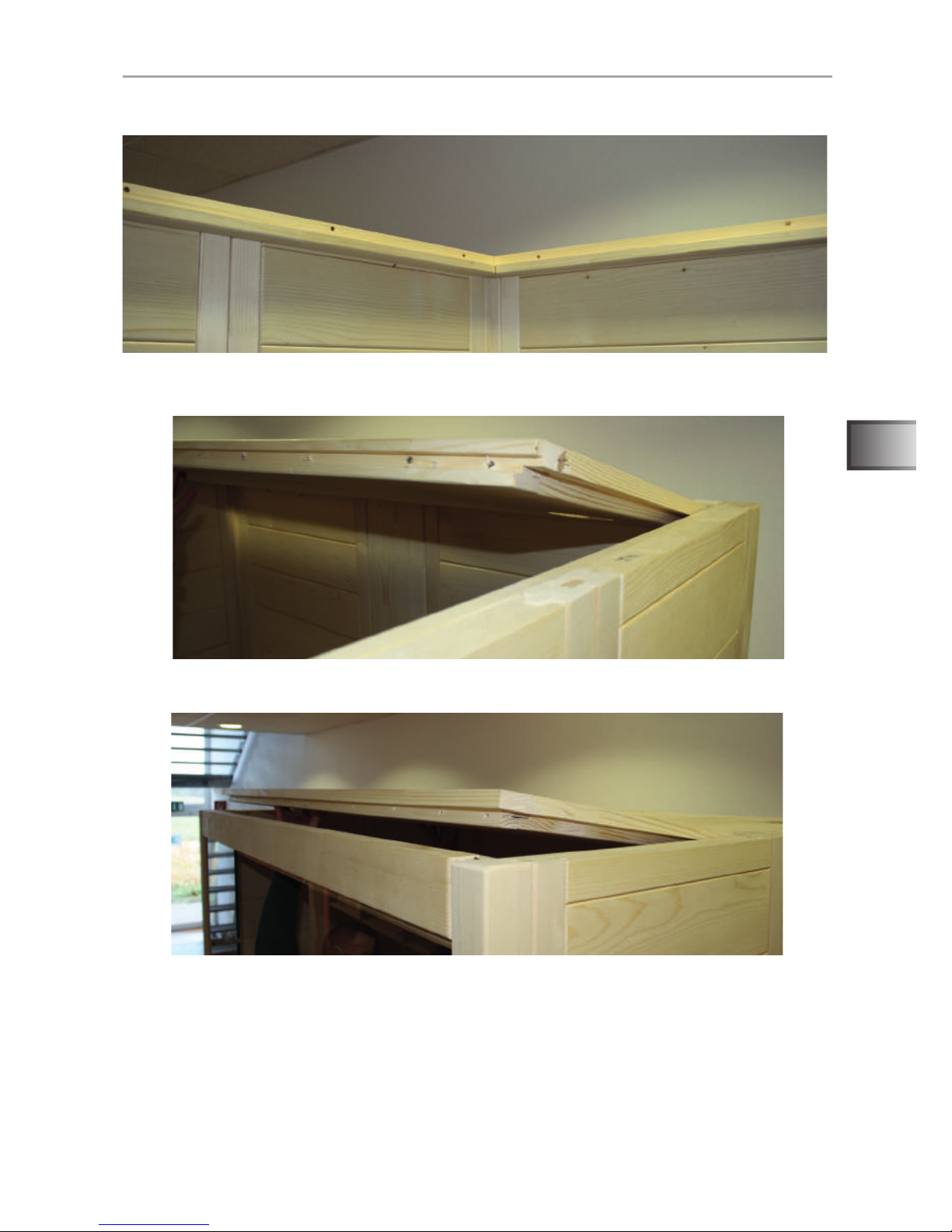
Fig. 14: Roof support slats installation
Attach skirting by squeezing the side wall elements until the anchors are no
longer visible.
Screw the roof support slats on all the walls of the cabin rmly, as shown in Figures Abb. 14 and Abb. 15. Be sure that the wall elements and the roof support
slat are ush.
WARNING!
Be sure that each support slat is correctly attached and that all of the
screws have been used.
Roof element installation
Screws
14 units: 3.5 x 50
Check the right angle alignment of the cabin in the corners or use the measuring
tape to measure the two diagonals of the cabin; if these are the same length,
the cabin is properly aligned.
Fig. 15: Attaching the skirting

WORLD OF WELLNESS
EN
Instructions for installation and use p. 19/44
Fig. 16: Roof support slats
Fig. 17: Installing the roof element in the back with the fan cut-out
Fig. 18: Installing the roof element in the front

WORLD OF WELLNESS
Instructions for installation and use p. 20/44
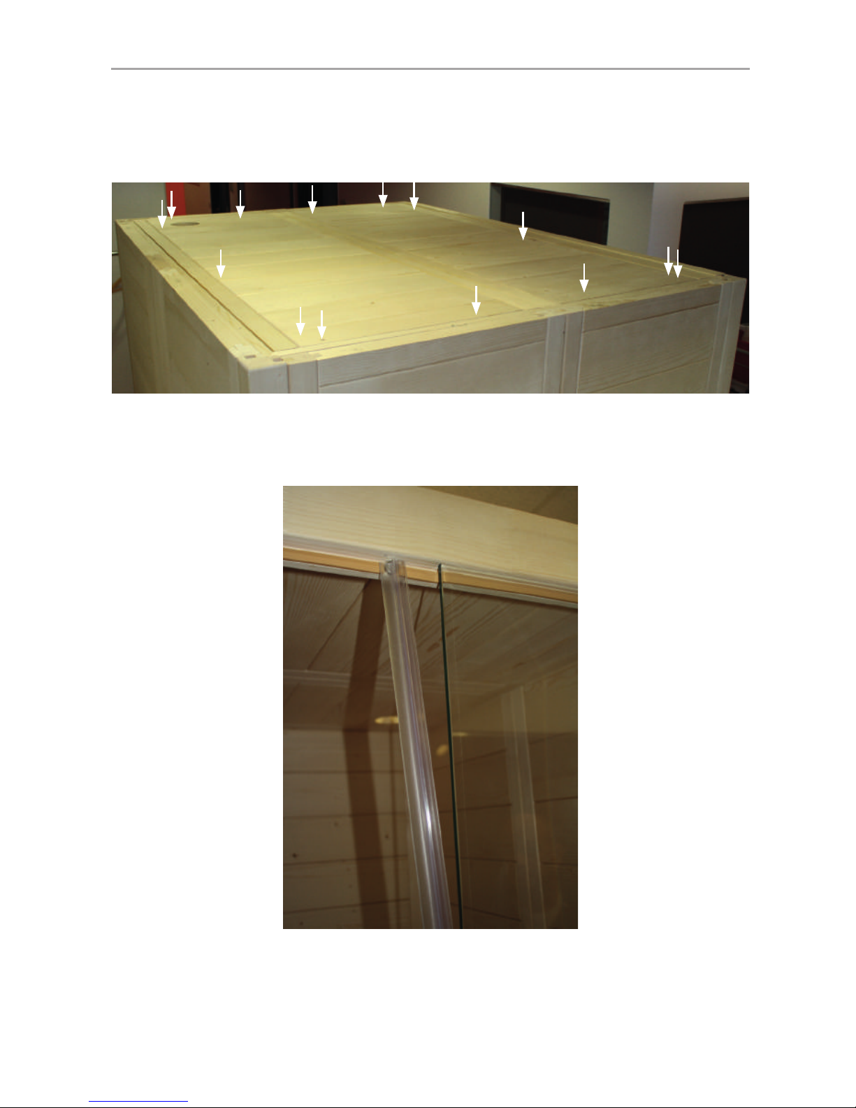
Fig. 19: Attaching the roof element
Fig. 20: Installing the door insulation strips
The insulation is placed on the glass element which does not have any holes
for the door ttings. Make sure that the stop of the insulation is on the inside.
Door installation
Screws
14 units: 3.5 x 35
After the roof elements have been inserted, they have to be screwed in with the
roof support slat.

WORLD OF WELLNESS
EN
Instructions for installation and use p. 21/44
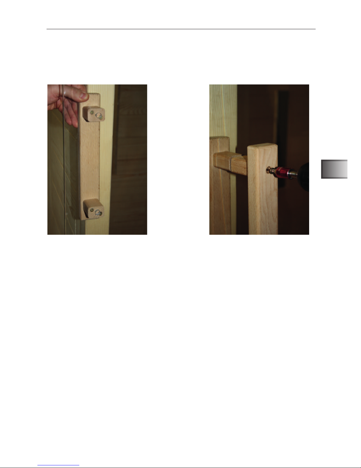
First, set the two silicone inserts in the holes for the door handle in the glass
element. Then, screw the two handles together carefully.
Fig. 21: Door handle installation
Screws
2 units: 3.5 x 70
The bottom hole of the door handle is at a height of 92.5 cm. The door handles
are screwed together from outside.

WORLD OF WELLNESS
Instructions for installation and use p. 22/44
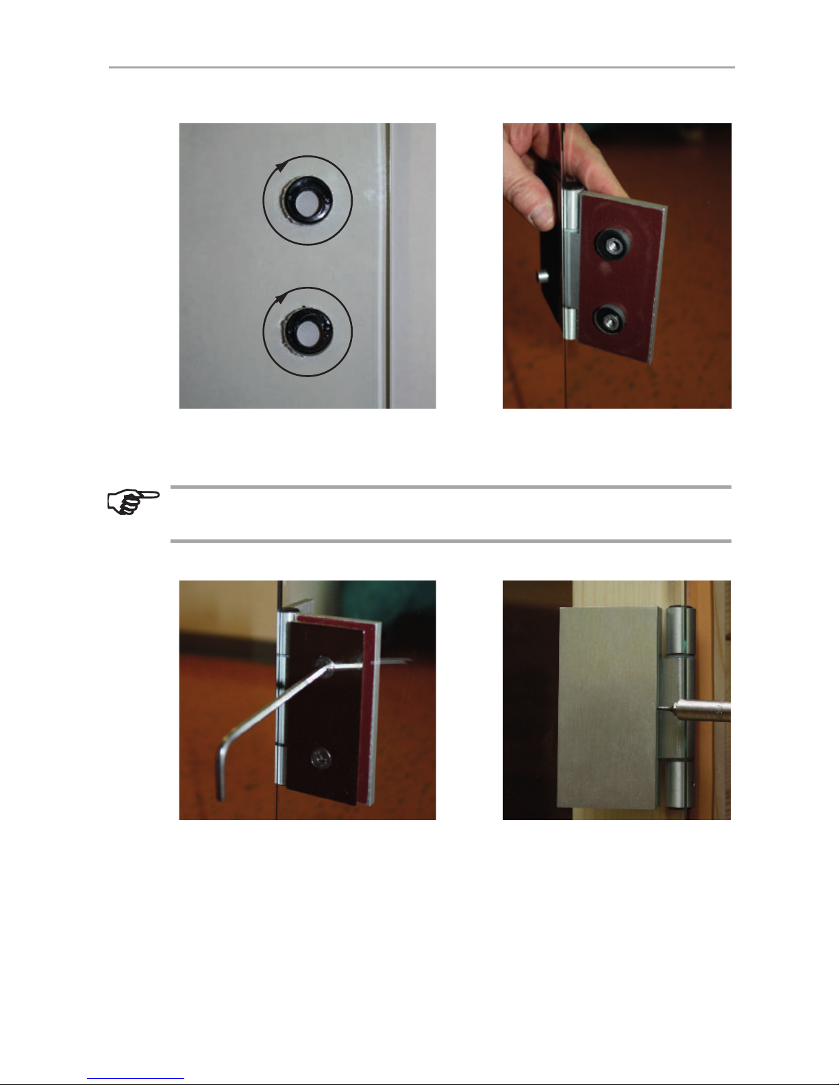
Fig. 22: Installation of Door Fitting 1
Screw the two door ttings onto the x-glass element, making sure of the straight
alignment of the ttings and that the door opens to the outside.
The ttings are aligned through the adjustment/rotation of the two plastic
rings.
Fig. 23: Installation of Door Fitting 2
Follow the steps in Abb. 22 and Abb. 23 again to connect the door leaf with the
x glass element.
Finally, set the blind in place and attach it rmly by tightening the Allen screw.

WORLD OF WELLNESS
EN
Instructions for installation and use p. 23/44
Fig. 24: Door magnet installation
The magnet for the door has to be on the side to which the door opens.
Mount the magnet on the appropriate side, if appropriate.
Cut the door insulation over the recess for the magnet with a sharp knife and
expose the recess. Using a small wooden block, hit the door magnetic with the
hammer in the recess. Adjust the length of the insulation to the magnet.
Fig. 25: Installation of the transfer plate
Slide the transfer plate at the spot on the glass door on which the magnet is
located on the skirting.

WORLD OF WELLNESS
Instructions for installation and use p. 24/44
Fig. 26: Completed wall elements and roof elements
Fig. 27: Install the attachment for the cabin oor
Installing the cabin oor

WORLD OF WELLNESS
EN
Instructions for installation and use p. 25/44
Fig. 28: Put the cabin oor in place
Front radiator installation
Fig. 29: Attach the front radiator in place
Make sure that the cables of the front radiator are exposed at the bottom
and are not pinched or damaged by the cabin oor.

WORLD OF WELLNESS
Instructions for installation and use p. 26/44
Fig. 30: Attach the front radiator in place
After the radiators are locked in at the bottom, attach each one rmly with a 90°
rotation on the Allen screws in a clockwise direction at the four attachment points.
Fig. 31: Inserting the soapstone bowls

WORLD OF WELLNESS
EN
Instructions for installation and use p. 27/44
Fig. 32: Installation of the bench cushion
Screw in the bench cushion left and right in the cabin as well as the bench cushion
bar on the electric element with 2 screws each.
Fig. 33: Installation of the U-strips for the thermal plates
Screw in the U-strips for thermal plates left and right in the cabin with 2 screws
each. Make sure that the switch is located at the top.
Installation of the bench cushion and the IR thermal plate
Screws
6 units: 5 x 70
41 cm
Screws
4 units: 3.5 x 50

WORLD OF WELLNESS
Instructions for installation and use p. 28/44
Fig. 34: Installation of the IR thermal plate VitaMy 164
Install the two IR thermal plates VitaMy 164 in the U-strips. The recess is used
to perform the management of the front beam (see Fig. 35)
When inserting the IR thermal plate, pay attention to the cable of the
switch; it has to not be pinched or damaged.
Fig. 35: Inserting the stiffener bar for the Vitamy IR thermal plates.
Lay the stiffener bar for the thermal plates from inside on the floor. Screw
the bar to the frame of the thermal plates. The recess is used to perform the
management of the front beam.
Screws
2 units: 3.5 x 50

WORLD OF WELLNESS
EN
Instructions for installation and use p. 29/44
Fig. 36: Ventilation installation
Screw together the base element of the vent and the 3 enclosed screws.
Then screw the wooden plate into place and secure the screw from the outside
with the plastic cap.
Ventilation installation

WORLD OF WELLNESS
Instructions for installation and use p. 30/44
Fig. 37: Installation of the LED cover strip
Use 3 screws to attach the LED cover strip to the ceiling from the outside.
Fig. 38: Glueing the LED strips in place
Glue the LED strips into place in the cover strip. The plug of the LED strips has
to extend far enough through the opening in the ceiling (see Fig. 39)
Installation of the LED cover strip
Screws
3 units: 3.5 x 50

WORLD OF WELLNESS
EN
Instructions for installation and use p. 31/44
Fig. 39: Connecting the LED strips with the control
Run the power supply of the LED lighting under the bench. Run the connecting
cable and the power cable through the opening in the rear wall towards the outside.
When connecting the LED strip, pay attention to the arrow on the plug.
This has to be on the side of the strip with the label "+ 12V". The mains
plug of the LED lighting has to be located outside of the cabin.
Connecting the LED strips
Fig. 40: Inserting the bench
Place the bench on the support slats.

WORLD OF WELLNESS
Instructions for installation and use p. 32/44
Fig. 41: Install the rear radiator (infrared radiator ECO 350)
Put the two radiators into the cutout from inside. Screw the radiators into place
with 4 screws each.
CAUTION!
Ensure that the junction box of the radiator on the top!
Installation of the read radiator
Screws
8 units: 3 x 18
Fig. 42: Installing the read radiator blind
Screw in the wood blinds of the radiators in front of the rear of the cabin with
4 screws each (available holes).
Screws
8 units: 3.5 x 50

WORLD OF WELLNESS
EN
Instructions for installation and use p. 33/44
4.4. Installation of the infrared control
Install the control panel in the designated place on the back wall of the cabin.
For the installation, commissioning and operation, follow the instructions
which are included which the control unit.
The operating mode "Room temperature control" is not supported by
the control.
Installing the control panel
Fig. 43: Installing the control panel
For the installation of the control unit, open the seat bench.
wave.com4
Infra

WORLD OF WELLNESS
Instructions for installation and use p. 34/44
The power supply of the control unit is placed under the bench of the cabin and
is connected as follows.
Connecting the power supply
Fig. 44: Power supply connections
Plug Description
1 wave.com4 Infra control panel
7 IR Heating Group 1
8 IR Heating Group 2
9 Mains connection
10 Fan connector (black) - optional
11 Light connection (green)

WORLD OF WELLNESS
EN
Instructions for installation and use p. 35/44
The power supply of the control unit is placed under the bench of the cabin and
is connected as follows.
Heating Group 1: Front radiator left, read radiator left, wall radiator left (above
switch)
Heating Group 2: Front radiator right, read radiator right, wall radiator right
(above switch)
The arrangement can be adapted to almost any preferences. However, each
connection can only accept a maximum of 750 W!
Arrangement of the heating groups
Fig. 45: Example for Heating Group 1
Read radiator leftThermal plate left
Thermal plate switch
Front radiator left
Thermal plate switch
T-Form distributor
GST18i/3s – GST18i/3B Cable

WORLD OF WELLNESS
Instructions for installation and use p. 36/44
4.5. Installation of the Bluetooth module (only VitaMy 164 BT)
Install the control panel in the designated place on the back wall of the cabin.
Before the installation, commissioning and operation, follow the instructions which are included which the Bluetooth module and the exciters.
Installing the control panel
Fig. 46: Installing the control panel
Screw the exciter with the provided screws in the left and right rear area on the
outside of the cabin ceiling.
Installation of the exciter
Fig. 47: Installation of the exciter
wave.com4
Bluetooth
wave.com4
Infra

WORLD OF WELLNESS
EN
Instructions for installation and use p. 37/44
Connect the exciter and the power supply onto the control panel according to
the instructions.
The mains supply has to be located outside of the cabin.
Connecting the control panel
Fig. 48: Connecting the control panel

WORLD OF WELLNESS
Instructions for installation and use p. 38/44
4.6. Installation of the sound & light (only VitaMy 164 S&L)
Install the control panel and the USB dock in the designated place on the back
wall of the cabin.
For the installation, commissioning and operation, follow the instructions
which are included which the sound & light colour light.
Installing the control panel and the USB dock
Install the colour lamp in the ceiling cutout using the provided screws. When
doing so, please refer to the enclosed instructions "wave.com4 sound&light".
Fig. 49: Installing the control panel
wave.com4
S&L
wave.com4
USB
wave.com4
Infra
Fig. 50: Installing the colour light
Connecting the colour light

WORLD OF WELLNESS
EN
Instructions for installation and use p. 39/44
Close the control panel, USB Dock and colour lamp according to the enclosed
instructions regarding the sound&light power adapter. Mount the power supply
preferably outside on the cabin ceiling or under the bench.
Connecting the control panel and the colour light
Fig. 51: Attaching the bench
Place the bench on the support slats. Push the seating areas forward.
4.7. Installation of the bench
After the control unit has been connected, the bench can be fully installed.
Screws
4 units: 4 x 70
CAUTION!
Secure the bench against sliding by using the locking screws on the
left and right of the bench cushion as well as on the bench support rail.

WORLD OF WELLNESS
Instructions for installation and use p. 40/44
Fig. 53: Installing the backrests of the bench
Screw the spacer strips to the rear wall (either ush or displaced inwardly up to
10 cm).
Screws
4 units: 4 x 70
Screw in the multi-clips using the mounting template with the accompanying screws.
Fig. 52: Installation of the spacer strips of the rear wall
4.8. Installation of spacer strips of the rear wall
4.9. Installation of the backrests and headrests of the bench

WORLD OF WELLNESS
EN
Instructions for installation and use p. 41/44
Screw in the brackets with at least 1 cm distance from the top edge of the frame,
laterally ush with the support of the backrest. The height can be varied as
desired. Then insert the head element in the desired position.
Fig. 54: Installation of the headrests
Remove the mounting template and insert the backrests downwards from above
onto the brackets until they t into place.

WORLD OF WELLNESS
Instructions for installation and use p. 42/44
5. Cleaning and maintenance
5.1. Cleaning
5.2. Maintenance
The VitaMy 164 infrared cabin is maintenance-free.
6. Troubleshooting
● For your own safety, consult your supplier in the event of problems that are
not explained in sufcient detail in the installation instructions.
ATTENTION!
Damage to the cabin
● Do not pour any water on the cabin or the electronic components.
● Do not use too much moisture when cleaning the cabin and the electronic
components.
● Please dispose of packaging materials in accordance with the
applicable disposal regulations.
● Used devices contain reusable materials and hazardous substances.
Therefore, do not dispose of your used device with household waste,
but do so in accordance with the locally applicable regulations.
7. Disposal

WORLD OF WELLNESS
EN
Instructions for installation and use p. 43/44
8. Technical data
Ambient conditions
Storage temperature: - 25 °C to + 70 °C
Ambient temperature: 20 °C to + 30 °C
Relative humidity: max. 95%
9. oor plan
Since wood is a natural product, slight dimensional deviations are possible.
VitaMy 164 Basic / BT / S&L 164 x 120 x 202 cm
Electrical
Element

sentiotec GmbH world of wellness Oberregauer Straße 48 4844 Regau, Austria
Tel: +43 (0) 7672/277 20-567 Fax: +43 (0) 7672/277 20-801
E-mail: info@sentiotec.com www.sentiotec.com
 Loading...