

Sentiotec sound&light+, infracontrol+, saunacontrol+, bluetooth+, infracontrol mini+ Instructions For Installation And Use Manual
...
saunacontrol+ Bedienteil
S-SC-C / 1-035-499
infracontrol+ Bedienteil
S-IRC-C / 1-035-500
sound&light+ Bedienteil
S-S&L-C / 1-035-501
sound&light+ USB Dock
S-S&L-USB / 1-035-669
bluetooth+
S-BT / 1-037-373
infracontrol mini+ Set
S-IRC-C-MN-S / 1-035-976
DE
Abschlussblenden Set
S-CCS / 1-035-503
MONTAGEANWEISUNG
Deutsch
Version 12/18 Ident-Nr. 1-039-445
EN

Inhaltsverzeichnis
1. Zu dieser Anleitung 3
2. Wichtige Hinweise zu Ihrer Sicherheit 4
2.1. Bestimmungsgemäßer Gebrauch 4
2.2. Sicherheitshinweise für den Monteur 5
2.3. Sicherheitshinweise für den Anwender 5
3. Produktbeschreibung 7
3.1. Lieferumfang bei saunacontrol+, infracontrol+, sound&light+,
sound&light+ USB Dock 7
3.2. Lieferumfang bei infracontrol mini+ Set 7
3.3. Lieferumfang bei bluetooth+ 7
3.4. Lieferumfang bei Abschlussblenden Set 7
4. Montage 8
4.1. Saunasteuerung montieren 8
5. Technische Daten 13

Montage- und Gebrauchsanweisung S. 3/14
1. Zu dieser Anleitung
Lesen Sie diese Montageanweisung gut durch und bewahren Sie sie in der
Nähe der Saunasteuerung auf. So können Sie jederzeit Informationen zu Ihrer
Sicherheit und zur Bedienung nachlesen.
Sie nden diese Montage- und Gebrauchsanweisung auch im Download-
bereich unserer Webseite auf www.sentiotec.com/downloads.
Symbole in Warnhinweisen
In dieser Montage- und Gebrauchsanweisung ist vor Tätigkeiten, von denen eine
Gefahr ausgeht, ein Warnhinweis angebracht. Befolgen Sie diese Warnhinweise
unbedingt. So vermeiden Sie Sachschäden und Verletzungen, die im schlimmsten
Fall sogar tödlich sein können.
In den Warnhinweisen werden Signalwörter verwendet, die folgende Bedeutungen haben:
GEFAHR!
Wenn Sie diesen Warnhinweis nicht beachten, sind Tod oder schwere
Verletzungen die Folge.
WARNUNG!
Wenn Sie diesen Warnhinweis nicht beachten, können Tod oder schwere
Verletzungen die Folge sein.
VORSICHT!
Wenn Sie diesen Warnhinweis nicht befolgen, können leichte Verletzungen die Folge sein.
ACHTUNG!
Dieses Signalwort warnt Sie vor Sachschäden.
Andere Symbole
Dieses Symbol kennzeichnet Tipps und nützliche Hinweise.
DE
Montage- und Gebrauchsanweisung S. 4/14
2. Wichtige Hinweise zu Ihrer Sicherheit
Die Bedienteile (siehe Seite 1) sind nach anerkannten sicherheitstechnischen Regeln gebaut. Dennoch können bei der Verwendung
Gefahren entstehen. Befolgen Sie deshalb die folgenden Sicherheitshinweise und die speziellen Warnhinweise in den einzelnen
Kapiteln. Beachten Sie auch die Sicherheitshinweise der angeschlossenen Geräte.
2.1. Bestimmungsgemäßer Gebrauch
Die Bedienteile dienen ausschließlich zum Steuern und Regeln
der Funktionen gemäß den technischen Daten der zugehörigen
Leistungsteile.
● Beachten Sie die Anleitungen der zugehörigen Leistungsteile. Tabelle 1
zeigt die Zuordnung der Bedienteile zu den jeweiligen Leistungsteilen.
Jeder darüber hinausgehende Gebrauch gilt als nicht bestimmungsgemäß. Nicht bestimmungsgemäßer Gebrauch kann zur Beschädigung des Produkts, zu schweren Verletzungen oder Tod führen.
Tabelle 1 - Übersicht Bedienteile und zugehörige Leistungsteile
Bedienteil Leistungsteil
saunacontrol+ Bedienteil
S-SC-C / 1-035-499
infracontrol+ Bedienteil
S-IRC-C / 1-035-500
sound&light+ Bedienteil
S-S&L-C / 1-035-501
sound&light+ USB Dock
S-S&L-USB / 1-035-669
sentiotec bluetooth+
S-BT / 1-037-373
Set aus Bedienteil und Leistungsteil
infracontrol mini+ Set S-IRC-C-MN-S / 1-035-976
wave.com4 Basismodul für Sauna
WC4-B-L / 1-008-153
Leistungsteil wave.com4 Infra
WC4-IRX-P / 1-012-083
wave.com4 sound&light Farblampe
WC4-SL-L / 1-010-274
-

Montage- und Gebrauchsanweisung S. 5/14
2.2. Sicherheitshinweise für den Monteur
● Die Montage darf nur durch eine Elektrofachkraft oder eine ver-
gleichsweise qualizierte Person ausgeführt werden.
● Arbeiten an den Steuerungen dürfen nur im spannungsfreien
Zustand durchgeführt werden.
● Es ist bauseits eine allpolige Trennvorrichtung mit voller Abschal-
tung entsprechend der Überspannungskategorie III vorzusehen.
● Die Bedienteile sind für die Montage innerhalb oder außerhalb
der Kabine geeignet. Beachten sie
● Beachten Sie auch die örtlichen Bestimmungen am Aufstellort.
● Bei Problemen, die in den Montageanweisungen nicht ausführ-
lich genug behandelt werden, wenden Sie sich zu Ihrer eigenen
Sicherheit an Ihren Lieferanten.
2.3. Sicherheitshinweise für den Anwender
● Die Bedienteile dürfen nicht von Kindern unter 8 Jahren verwen-
det werden.
● Das Bedienteil darf von Kindern über 8 Jahren, von Personen mit
verringerten psychischen, sensorischen oder mentalen Fähigkeiten und von Personen mit Mangel an Erfahrung und Wissen
unter folgenden Bedingungen verwendet werden:
– wenn sie beaufsichtigt werden
– wenn ihnen die sichere Verwendung gezeigt wurde und sie
die Gefahren, die entstehen können, verstehen.
● Kinder dürfen nicht mit den Bedienteilen spielen.
● Kinder unter 14 Jahren dürfen die Bedienteile nur reinigen, wenn
sie beaufsichtigt werden.
DE

Montage- und Gebrauchsanweisung S. 6/14
● Wenn Sie unter dem Einuss von Alkohol, Medikamenten oder
Drogen stehen, verzichten Sie aus gesundheitlichen Gründen
auf das Saunabad.
● Stellen Sie sicher, dass keine brennbaren Gegenstände auf dem
Saunaofen liegen, bevor Sie die Saunasteuerung einschalten.
● Stellen Sie sicher, dass keine brennbaren Gegenstände auf dem
Saunaofen liegen, bevor Sie die Vorwahlzeitfunktion oder den
Standby-Modus für den Fernstart aktivieren.
● Stellen Sie sicher, dass keine brennbaren Gegenstände auf
oder vor dem Infrarot-Strahler liegen, bevor Sie die Steuerung
einschalten.
● Stellen Sie sicher, dass keine brennbaren Gegenstände auf oder
vor dem Infrarot-Strahler liegen, bevor Sie die Vorwahlzeitfunktion
oder den Standby-Modus für den Fernstart aktivieren.
● Bei Problemen, die in der Gebrauchsanweisung nicht ausführ-
lich genug behandelt werden, wenden Sie sich zu Ihrer eigenen
Sicherheit an Ihren Lieferanten.
Montage- und Gebrauchsanweisung S. 7/14
3. Produktbeschreibung
3.1. Lieferumfang bei saunacontrol+, infracontrol+, sound&light+,
sound&light+ USB Dock
● Bedienteil
● Montageanleitung
● Montagematerial (2x Gewindestift M5x12mm, 2x Spax 3x20mm)
● Datenkabel
3.2. Lieferumfang bei infracontrol mini+ Set
● Bedienteil
– Montageanleitung
– Montagematerial (2x Gewindestift M5x12mm, 2x Spax 3x20mm)
– Datenkabel
● Leistungsteil
– Infrabox basic Leistungsteil
– Netzteilanschlussleitung
– Montagematerial
– Bedienungsanleitung
– HV-Stecker
DE
3.3. Lieferumfang bei bluetooth+
● Bluetooth-Modul bluetooth+
● Montagematerial (2x Gewindestift M5x12mm, 2x Spax 3x20mm)
● Montageanleitung
● Steckernetzteil mit Anschlusskabel (0,8 m)
● Verlängerungskabel für die Anschlussleitung zum Steckernetzteil (2 m)
● Bedienungsanleitung
3.4. Lieferumfang bei Abschlussblenden Set
● 2x Abschlussblende
● Montageanleitung
● Montagematerial (2x Gewindestift M5x12mm)
Montageanweisung – nur für Fachpersonal S. 8/14
4. Montage
4.1. Saunasteuerung montieren
Beachten Sie bei der Montage der Bedienteile folgende Punkte:
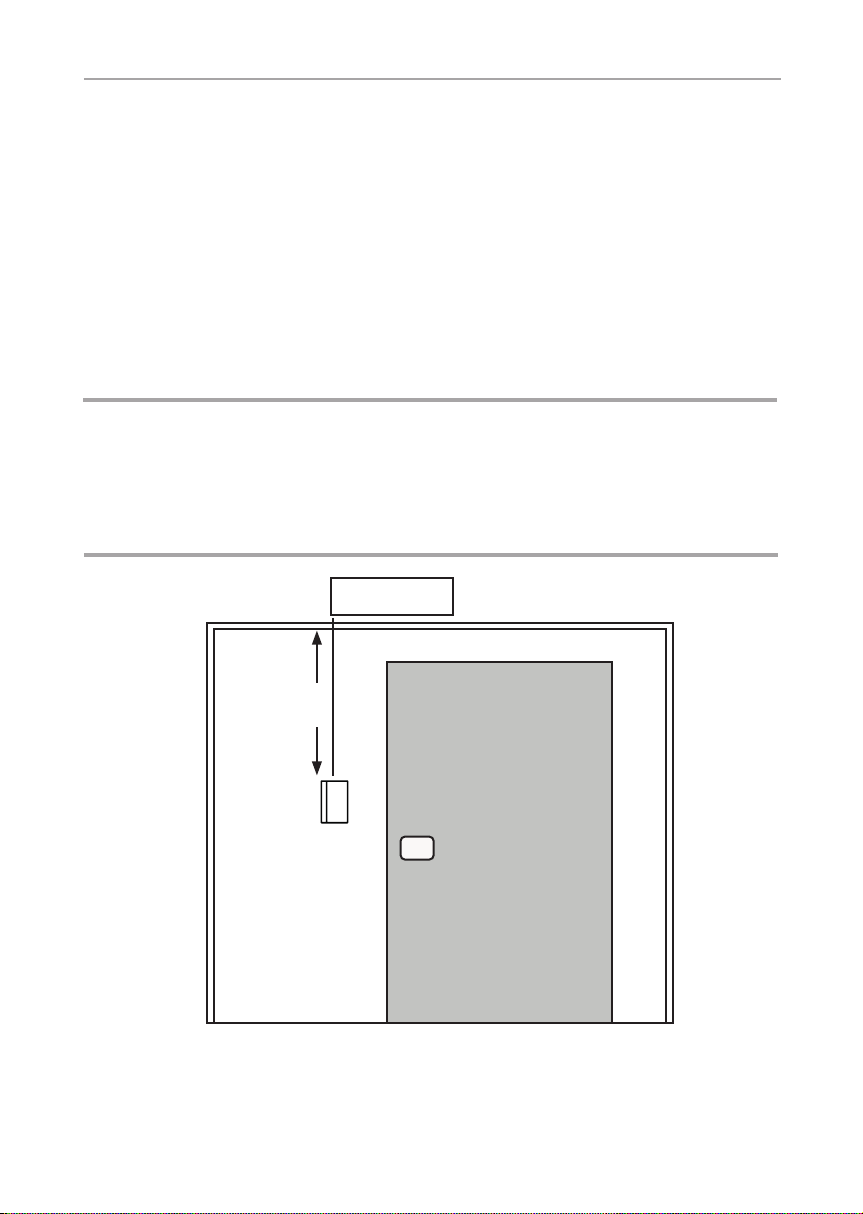
Das Bedienteil wird an der Kabinen-Außenwand (im maximalen Abstand von
10 Metern zum Leistungsteil) montiert (siehe Abb. 1). Für die Montage wird
beispielsweise eine handelsübliche Stichsäge oder eine Oberfräse benötigt um
die Ausnehmung für das Bedienteil zu schneiden. Das Bedienteil kann sowohl
in der Kabine als auch außerhalb der Kabine montiert werden. *Bei Montage
innerhalb einer Saunakabine ist ein Mindesabstand von 30 cm zur Kabinendecke
einzuhalten (siehe Abb.2).
ACHTUNG!
Schäden am Gerät
● Die Bedienteile sind spritzwassergeschützt (Schutzgrad IP X4).
● Arbeiten am Bedienteil dürfen nur mit einem normalen Schraubendreher
durchgeführt werden. Bei Verwendung eines Akkuschraubers besteht die
Gefahr, dass das Gehäuse irreparabel beschädigt wird!
min. 30 cm *
Bedienteil
Abb. 2 Position Bedienteil
* bei Montage innerhalb der Kabine
(Leistungsteil)
Außenansicht
Montageanweisung – nur für Fachpersonal S. 9/14
1. Mit beispielsweise einer Stichsäge oder einer Oberfräse die entsprechende
Ausnehmung (siehe Seite 11, 12) vornehmen.
2. Leitungsführungen für die Verbindungsleitung vorsehen.
3. Bedienteil mit den beiden beiliegenden Holzschrauben an die Kabinenwand
schrauben.
DE
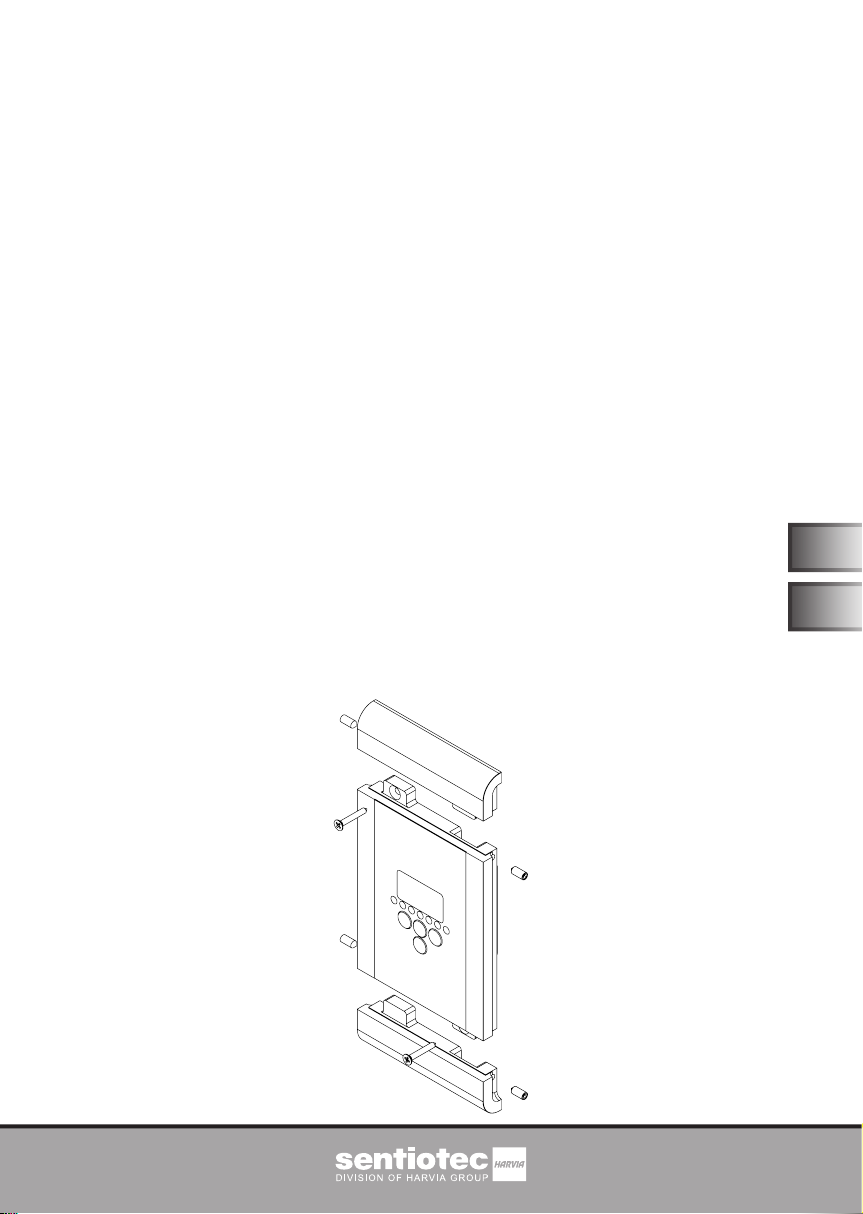
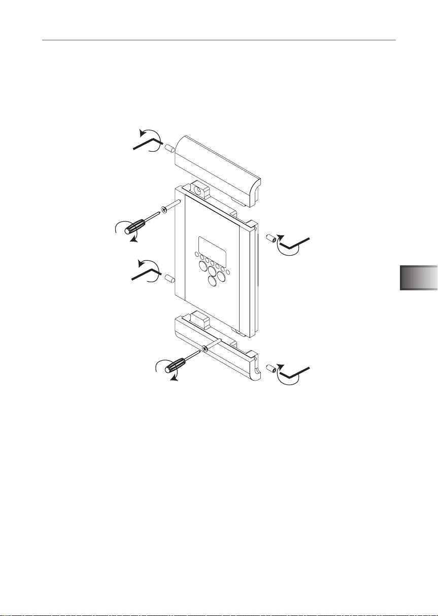
Abb. 3 Montage Bedienteil
4. Befestigen Sie die beiden Abschlussblenden am Bedienteil. Verwenden Sie
dazu die beiden beiliegenden Gewindestifte und einen Inbuschlüssel. Ziehen
Sie die Gewindestifte vorsichtig fest.
Montage mehrer Bedienteile übereinander:
Verbinden Sie die Bedienteile mit den beiliegenen Gewindestiften miteinander.
Schrauben Sie diese anschließend an der Positions des Ausschnitts an der Kabinenwand fest und befestigen Sie die Abschlussblenden (siehe Abb. 4).

Montageanweisung – nur für Fachpersonal S. 10/14
Abb. 4 Montage mehrerer Bedienteile

Montage- und Gebrauchsanweisung S. 11/14
Ausschnitt für Bedienteil: saunacontrol+, infracontrol+, sound&light+,
bluetooth+
Maße in mm
90 ±5
A
90 ±5
25 ±2
A
Ausschnitt für Bedienteil: infracontrol mini+
Maße in mm
50 ±5
90 ±5
A
A
DE
SCHNITT A-A
25 ±2
SCHNITT A-A

Montage- und Gebrauchsanweisung S. 12/14
Ausschnitt für Bedienteil: sound&light+ USB Dock
Maße in mm
95 ±5
A
40 ±5
30 ±2
A
SCHNITT A-A

Montage- und Gebrauchsanweisung S. 13/14
5. Technische Daten
Umgebungsbedingungen
Lagertemperatur: -25 °C bis +70 °C
Umgebungstemperatur: 0 °C bis 100 °C
Luftfeuchtigkeit: max. 99%
nicht kondensierend
Abmessungen saunacontrol+, infracontrol+, sound&light+, bluetooth+
Abmessungen (mit Abschlussblenden): 110 x 195 x 38,5 mm
Schutzart (spritzwassergeschützt): IPX4
Abmessungen sound&light USB Dock+
Abmessungen (mit Abschlussblenden): 110 x 115 x 39 mm
Schutzart (spritzwassergeschützt): IPX4
Abmessungen bluetooth+
Abmessungen (mit Abschlussblenden): 110 x 195 x 33 mm
Schutzart (spritzwassergeschützt): IPX4
Abmessungen infracontrol mini+
Abmessungen (mit Abschlussblenden): 110 x 115 x 38,5 mm
Schutzart (spritzwassergeschützt): IPX4
DE

NOTIZEN / APPUNTI / NOTES / NOTE / NOTITIES
………………………………………………….............………………………………………………………………...
…………………………………………………………….......……………………………………………………………...
…………………………………………………………….............………………………………………………………...
…………………………………………………….............………………………………………………………………...
……………………………………………………………......……………………………………………………………...
……………………………………………………………......……………………………………………………………...
……………………………………………………………..........…………………………………………………………...
…………………………………………………………….............………………………………………………………...
…………………………………………………………….............………………………………………………………...
…………………………………………………………….............………………………………………………………...
…………………………………………………………….............………………………………………………………...
…………………………………………………………….............………………………………………………………...
.…………………………………………………………….............………………………………………………………...
…………………………………………………………….............………………………………………………………...
…………………………………………………………….............………………………………………………………...
…………………………………………………………….............………………………………………………………...
…………………………………………………………….............………………………………………………………...
…………………………………………………………….............………………………………………………………...
…………………………………………………………….............………………………………………………………...

saunacontrol+ operating unit
S-SC-C / 1-035-499
infracontrol+ operating unit
S-IRC-C / 1-035-500
sound&light+ operating unit
S-S&L-C / 1-035-501
sound&light+ USB dock
S-S&L-USB / 1-035-669
bluetooth+
S-BT / 1-037-373
infracontrol mini+ set
S-IRC-C-MN-S / 1-035-976
Cover panel set
S-CCS / 1-035-503
INSTRUCTIONS FOR INSTALLATION AND USE
English
Version 12/18 ID no. 1-039-445
EN

Table of Contents
1. About this instruction manual 3
2. Important information for your safety 4
2.1. Intended use 4
2.2. Safety information for the installer 5
2.3. Safety information for the user 5
3. Product description 7
3.1. Scope of delivery for saunacontrol+, infracontrol+,
sound&light+, sound&light+ USB dock 7
3.2. Scope of delivery for infracontrol mini+ set 7
3.3. Scope of delivery for bluetooth+ 7
3.4. Scope of delivery for cover panel set 7
4. Installation 8
4.1. Installing the sauna control unit 8
5. Technical data 13

Instructions for installation and use p. 3/14
1. About this instruction manual
Read these installation instructions carefully and keep it within reach when using
the sauna control unit. This ensures that you can refer to information about your
safety and the operation at any time.
These installation and operating instructions can also be found in the
downloads section of our website: www.sentiotec.com/downloads.
Symbols used for warning notices
In these instructions for installation and use, a warning notice located next to
an activity indicates that this activity poses a risk. Always observe the warning
notices. This prevents damage to property and injuries, which in the worst case
may be fatal.
The warning notices contain keywords, which have the following meanings:
DANGER!
Serious or fatal injury will occur if this warning notice is not observed.
WARNING!
Serious or fatal injury can occur if this warning notice is not observed.
CAUTION!
Minor injuries can occur if this warning notice is not observed.
ATTENTION!
This keyword is a warning that damage to property can occur.
Other symbols
This symbol indicates tips and useful information.
EN

Instructions for installation and use p. 4/14
2. Important information for your safety
The operating units (see page 1) have been made in accordance with
the safety regulations applicable for technical units. However, hazards may occur during use. Therefore adhere to the following safety
information and the specic warning notices in the individual chapters.
Also observe the safety information for the devices connected.
2.1. Intended use
The operating units may only be used for controlling and regulating
the functions in accordance with the technical data for the power
units used.
● Observe the instructions for the power units used. Table 1 shows the
allocation of the operating units to the respective power units.
Any use exceeding this scope is considered improper use. Improper
use can result in damage to the product, in severe injuries or death.
Table 1 – Overview of operating units and respective power units
Operating unit Power unit
saunacontrol+ operating unit
S-SC-C / 1-035-499
infracontrol+ operating unit
S-IRC-C / 1-035-500
sound&light+ operating unit
S-S&L-C / 1-035-501
sound&light+ USB dock
S-S&L-USB / 1-035-669
sentiotec bluetooth+
S-BT / 1-037-373
Set comprised of operating unit and power unit
infracontrol mini+ set S-IRC-C-MN-S / 1-035-976
wave.com4 basic sauna module
WC4-B-L / 1-008-153
Power unit wave.com4 Infra
WC4-IRX-P / 1-012-083
wave.com4 sound&light colour lamp
WC4-SL-L / 1-010-274
-

Instructions for installation and use p. 5/14
2.2. Safety information for the installer
● Installation may only be performed by a qualied electrician or
similarly qualied person.
● Work on the control units may only be performed when the power
has been disconnected.
● An all-pole disconnecting device with full cut-off compliant with
overvoltage category III must be tted on-site.
● The operating units are suitable for installation inside or outside
the cabin. Please observe
● Also comply with the regulations applicable at the installation
location.
● For your own safety, consult your supplier in the event of prob-
lems that are not explained in sufcient detail in the installation
instructions.
2.3. Safety information for the user
● The operating units must not be used by children under 8 years old.
● The operating unit may only be used by children over 8 years
old, by persons with limited psychological, sensory or mental
capabilities or by persons with lack of experience/knowledge
under the following conditions:
– They are supervised.
– They have been shown how to use the device safely and
are aware of the hazards that could occur.
● Children must not play with the operating units.
● Children under 14 years of age may only clean the operating unit
if they are supervised.
EN

Instructions for installation and use p. 6/14
● For health reasons, do not use the sauna when under the inu-
ence of alcohol, medication or drugs.
● Make sure that no ammable objects have been placed on the
sauna heater before the sauna control unit is switched on.
● Make sure that no ammable objects have been placed on the
heater before activating the preset time function or the stand-by
mode for the remote start.
● Make sure that no ammable objects have been placed on or in
front of the infrared lamp before the control unit is switched on.
● Make sure that no ammable objects have been placed on the
infrared lamp before activating the preset time function or the
stand-by mode for the remote start.
● For your own safety, consult your supplier in the event of prob-
lems that are not described in sufcient detail in the operating
instructions.

Instructions for installation and use p. 7/14
3. Product description
3.1. Scope of delivery for saunacontrol+, infracontrol+,
sound&light+, sound&light+ USB dock
● Operating unit
● Assembly instructions
● Installation material (2x Allen set screws M5x12 mm, 2x spax 3x20 mm)
● Data cable
3.2. Scope of delivery for infracontrol mini+ set
● Operating unit
– Assembly instructions
– Installation material (2x Allen set screws M5x12 mm, 2x spax 3x20 mm)
– Data cable
● Power unit
– Infrabox basic power unit
– Power supply unit connection cable
– Installation material
– Installation instruction manual
– HV plug
EN
3.3. Scope of delivery for bluetooth+
● Bluetooth module bluetooth+
● Installation material (2x Allen set screws M5x12 mm, 2x spax 3x20 mm)
● Assembly instructions
● Wall power supply with connection cable (0.8 m)
● Extension cable for connecting cable to the wall power supply (2 m)
● Installation instruction manual
3.4. Scope of delivery for cover panel set
● 2x cover panels
● Assembly instructions
● Installation material (2x Allen set screws M5x12 mm)

Installation instructions, for professionals only p. 8/14
4. Installation
4.1. Installing the sauna control unit
Observe the following points when installing the operating unit:
The operating unit is installed on the outside wall of the cabin (with a maximum
clearance of 10 metres from the power unit) (see Fig. 1). For the installation,
a standard jigsaw or a router is required to cut out the recess for the operating unit. The operating unit can be installed both inside and outside the cabin.
*For installation inside a sauna cabin, a minimum clearance of 30 cm to the cabin
roof must be maintained (see Fig. 2).
ATTENTION!
Damage to the unit
● The operating units are protected against splashing water (protection class IP X4).
● Work on the operating unit must only be carried out using a standard screwdriver.
Using a cordless screwdriver may cause irreparable damage to the housing.
(Power unit)
min. 30 cm *
Operating
unit
Fig. 2 Position of the operating unit
* for assembly inside the cabin
External view

Installation instructions, for professionals only p. 9/14
1. Using a jig saw or a router, for example, cut the corresponding recess
(see pages 11 & 12).
2. Provide cable guides for the connecting cable.
3. Screw the operating unit to the cabin wall using the two wood screws provided.
EN
Fig. 3 Installation of the operating unit
4. Attach the two cover panels to the operating unit. Use the two Allen set screws
and an Allen key to do so. Carefully tighten the Allen set screws.
Installing several operating units above each other:
Connect to the operating units to each other using the Allen set screws provided.
Then screw these to the cabin wall in the same position as the recess, and attach
the cover panels (see Fig. 4).

Installation instructions, for professionals only p. 10/14
Fig. 4 Installation of several operating units

Instructions for installation and use p. 11/14
Recess for operating unit: saunacontrol+, infracontrol+, sound&light+,
bluetooth+
Dimensions in mm
90 ±5
A
90 ±5
25 ±2
A
Recess for operating unit: infracontrol mini+
Dimensions in mm
50 ±5
90 ±5
A
A
SCHNITT A-A
EN
25 ±2
SCHNITT A-A

Instructions for installation and use p. 12/14
Recess for operating unit: sound&light+ USB dock
Dimensions in mm
95 ±5
A
40 ±5
30 ±2
A
SCHNITT A-A

Instructions for installation and use p. 13/14
5. Technical data
Ambient conditions
Storage temperature: -25 °C to +70 °C
Ambient temperature: 0 °C to 100 °C
Relative humidity: max. 99%
non-condensing
Dimensions of saunacontrol+, infracontrol+, sound&light+, bluetooth+
Dimensions (with cover panels): 110 x 195 x 38.5 mm
Protection type (protected against splashing water): IPX4
Dimensions of sound&light USB dock+
Dimensions (with cover panels): 110 x 115 x 39 mm
Protection type (protected against splashing water): IPX4
Dimensions of bluetooth+
Dimensions (with cover panels): 110 x 195 x 33 mm
Protection type (protected against splashing water): IPX4
EN
Dimensions of infracontrol mini+
Dimensions (with cover panels): 110 x 115 x 38.5 mm
Protection type (protected against splashing water): IPX4

sentiotec GmbH | Division of Harvia Group | Oberregauer Straße 48, A-4844 Regau
T +43 (0) 7672/277 20-567 | F -801 | info@sentiotec.com | www.sentiotec.com
 Loading...