

Version 11/14 Ident-Nr. 50950078
DE
EN
MONTAGE- UND GEBRAUCHSANWEISUNG
Deutsch
36
Infrarotsteuerung
IS1
P-IS1-T

WORLD OF WELLNESS
Inhaltsverzeichnis
1. Zu dieser Anleitung 3
2. Wichtige Hinweise zu Ihrer Sicherheit 4
2.1. Bestimmungsgemäßer Gebrauch 4
2.2. Sicherheitshinweise für den Monteur 5
2.3. Sicherheitshinweise für den Anwender 6
3. Produktbeschreibung 7
3.1. Lieferumfang 7
3.2. Optionales Zubehör 7
3.3. Produktfunktionen 7
4. Montage 8
4.1. Vorbereiten der Montage - Aufputz 8
4.2. Vorbereitung der Montage - versenkte Montage 9
4.3. Gehäuse vorbereiten 9
5. Elektrischer Anschluss 10
5.1. Abnehmen des vorderen Deckels 12
6. Endmontage 13
6.1. Endmontage - Aufputz 13
6.2. Endmontage - versenkte Montage 14
6.3. Fühlermontage 15
7. Ändern der Heizzeitbegrenzung 16
8. Bedienung 17
8.1. Bedien- und Anzeigeelemente 17
8.2. Schnellstart 18
8.3. Beschreibung der Funktionen und Bedienelemente 19
9. Problemlösung 21
10. Entsorgung 22
11. Technische Daten 22

WORLD OF WELLNESS
DE
Montage- und Gebrauchsanweisung S. 3/22
1. Zu dieser Anleitung
Lesen Sie diese Montage- und Gebrauchsanweisung gut durch und bewahren
Sie sie in der Nähe der Infrarotsteuerung auf. So können Sie jederzeit Informationen zu Ihrer Sicherheit und zur Bedienung nachlesen.
Symbole in Warnhinweisen
In dieser Montage- und Gebrauchsanweisung ist vor Tätigkeiten, von denen eine
Gefahr ausgeht, ein Warnhinweis angebracht. Befolgen Sie diese Warnhinweise
unbedingt. So vermeiden Sie Sachschäden und Verletzungen, die im schlimmsten
Fall sogar tödlich sein können.
In den Warnhinweisen werden Signalwörter verwendet, die folgende Bedeutungen haben:
GEFAHR!
Wenn Sie diesen Warnhinweis nicht beachten, sind Tod oder schwere
Verletzungen die Folge.
WARNUNG!
Wenn Sie diesen Warnhinweis nicht beachten, können Tod oder schwere
Verletzungen die Folge sein.
VORSICHT!
Wenn Sie diesen Warnhinweis nicht befolgen, können leichte Verletzungen die Folge sein.
ACHTUNG!
Dieses Signalwort warnt Sie vor Sachschäden.
Andere Symbole
Dieses Symbol kennzeichnet Tipps und nützliche Hinweise.
Sie nden die aktuellen Montage- und Gebrauchsanweisungen im Down-
loadbereich unserer Webseite auf www.sentiotec.com/downloads.

WORLD OF WELLNESS
Montage- und Gebrauchsanweisung S. 4/22
2. Wichtige Hinweise zu Ihrer Sicherheit
Die Infrarotsteuerung IS1 ist nach anerkannten sicherheitstechnischen Regeln gebaut. Dennoch können bei der Verwendung
Gefahren entstehen. Befolgen Sie deshalb die folgenden Sicherheitshinweise und die speziellen Warnhinweise in den einzelnen
Kapiteln.
2.1. Bestimmungsgemäßer Gebrauch
Die Infrarotsteuerung IS1 dient zum Steuerung und Regeln der
Innenraumtemperatur sowie zur Bedienung des Kabinenlichts. Die
Infrarotsteuerung darf nur zum Steuern von einem Heizkreis mit
einer Leistung von max. 3,6 kW verwendet werden.
Geeignete Infrarotstrahler: DIR-350-R, WIR-350-R, DIR-500-R,
WIR-500-R, DIR-750-R, WIR-750-R, DIR-1300-R, WIR-1300-R,
ECO-350-R, ECO-350-G, ECO-500-R, ECO-500-G, ECO-750-R,
O-IRC-W
Geeignete Infrarotplatten: IR-WP-175, IR-WP-100, IR-WP-390, IRWP-510, IR-WPHL-510, IR-WPHL-100, IR-WPHL-390, IR-WPHL-175
► Nur in Verbindung mit dem optionalen Folienfühler P-ISX-FF.
Jeder darüber hinausgehende Gebrauch gilt als nicht bestimmungsgemäß. Nicht bestimmungsgemäßer Gebrauch kann zur Beschädigung des Produkts, zu schweren Verletzungen oder Tod führen.

WORLD OF WELLNESS
DE
Montage- und Gebrauchsanweisung S. 5/22
2.2. Sicherheitshinweise für den Monteur
● Die Montage darf nur durch eine Elektrofachkraft oder eine ver-
gleichsweise qualizierte Person ausgeführt werden.
● Montage- und Anschlussarbeiten an der Infrarotsteuerung dürfen
nur im spannungsfreien Zustand durchgeführt werden.
● Der Temperaturfühler ist so anzubringen, dass er nicht durch
einströmende Luft beeinusst wird.
● Beachten Sie auch die örtlichen Bestimmungen am Aufstellort.
● Bei Problemen, die in den Montageanweisungen nicht ausführ-
lich genug behandelt werden, wenden Sie sich zu Ihrer eigenen
Sicherheit an Ihren Lieferanten.

WORLD OF WELLNESS
Montage- und Gebrauchsanweisung S. 6/22
2.3. Sicherheitshinweise für den Anwender
● Das Gerät darf nicht von Kindern unter 8 Jahren verwendet
werden.
● Das Gerät darf von Kindern über 8 Jahren, von Personen mit
verringerten psychischen, sensorischen oder mentalen Fähigkeiten und von Personen mit Mangel an Erfahrung und Wissen
unter folgenden Bedingungen verwendet werden:
– wenn sie beaufsichtigt werden.
– wenn ihnen die sichere Verwendung gezeigt wurde und sie
die Gefahren, die entstehen können, verstehen.
● Kinder dürfen nicht mit dem Gerät spielen.
● Kinder unter 14 Jahren dürfen das Gerät nur reinigen, wenn sie
beaufsichtigt werden.
● Wenn Sie unter dem Einuss von Alkohol, Medikamenten oder
Drogen stehen, verzichten Sie aus gesundheitlichen Gründen
auf die Benutzung der Infrarotkabine.
● Stellen Sie sicher, dass keine brennbaren Gegenstände auf oder
vor dem Infrarot-Strahler bzw. der Infrarot-Wärmeplatte liegen,
bevor Sie die Infrarotsteuerung einschalten.
● Bei Problemen, die in der Gebrauchsanweisung nicht ausführ-
lich genug behandelt werden, wenden Sie sich zu Ihrer eigenen
Sicherheit an Ihren Lieferanten.

WORLD OF WELLNESS
DE
Montage- und Gebrauchsanweisung S. 7/22
3. Produktbeschreibung
3.1. Lieferumfang
● Infrarotsteuerung IS1
● Netzanschlussleitung 1,6 m
● Raumfühler mit Silikonleitung 1,5 m
● Montagematerial
● Montage- und Gebrauchsanweisung
3.2. Optionales Zubehör
● IR-IS-A03 Adapterleitung für Strahler und Wärmeplatten (0,3 m)
● IR-IS-A25 Adapterleitung für Strahler und Wärmeplatten (2,5 m)
● IR-1P2 T-Verteiler 2-fach
● IR-1P3 Verteiler 3-fach
● IR-1P5 Verteiler 5-fach
● P-ISX-FF Folienfühler inkl. Kabel 3 m
● P-ISX-FUSE Feinsicherungseinsatz für Licht
● O-F2 Raumfühler
3.3. Produktfunktionen
Die Infrarotsteuerung IS1 dient zum Regeln der Kabinentemperatur über den
Raumfühler. Über die Bedienelemente können Einstellungen wie Soll-Temperatur,
Laufzeit und Licht vorgenommen werden. Die aktuelle Ist-Temperatur wird am
Display angezeigt. 1 Heizkreis für max. 3,6 kW Leistung ermöglicht den Anschluss
von Infrarot-Strahlern und/oder Infrarot-Wärmeplatten.
WORLD OF WELLNESS
Montageanweisung – nur für Fachpersonal S. 8/22
4. Montage
Die Infrarotsteuerung kann wahlweise aufputz oder versenkt montiert werden.
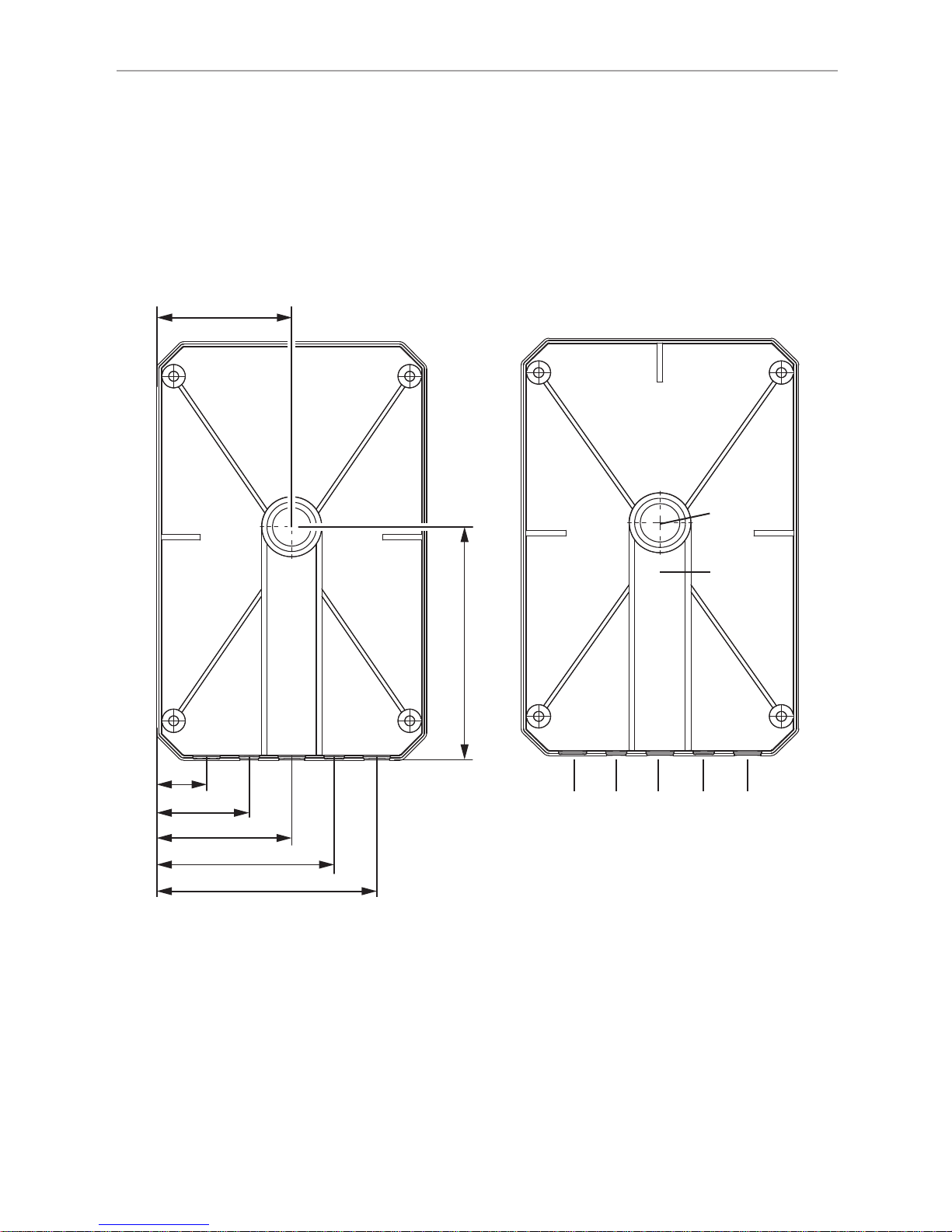
4.1. Vorbereiten der Montage - Aufputz
Um die Steuerung aufputz zu montieren sind Kabeldurchführungen in der Kabinenwand vorzusehen. Die Positionen entnehmen Sie der nachfolgenden Abbildung.
49
85
17,5
34
49
65
80,5
1
7
2 3 4 5 6
1 Durchlass Fühlerkabel
2 Netzzuleitung
3 Abgang Strahler/Folien
4 Frei
5 Frei
6 Abgang Licht
7 Kabelschacht
► Achtung: Wenn die Kabel über den
Kabelschacht 7 nach unten geführt
werden, muss dafür gesorgt werden,
dass die Fühlerkabel mit einer zusätzlichen Schutzisolation versehen
werden.
WORLD OF WELLNESS
DE
Montageanweisung – nur für Fachpersonal S. 9/22
4.2. Vorbereitung der Montage - versenkte Montage
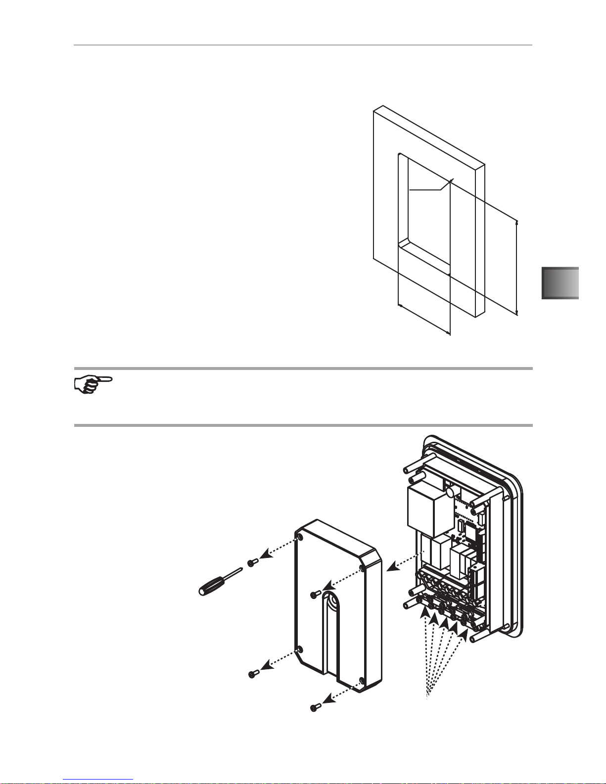
Um die Steuerung in der Wand zu versenken, wird ein Ausschnitt benötigt.
● Abmessungen Ausschnitt: 160 mm x 102 mm
● Einbautiefe: 39,5 mm
4.3. Gehäuse vorbereiten
102 mm
160 mm
R=5 mm
► Sorgen Sie für ausreichend
Hinterlüftung der Steuerung!
Arbeiten am Gehäuse dürfen nur mit einem normalen Schraubendreher
durchgeführt werden. Bei der Verwendung eines Akkuschraubers besteht
die Gefahr, dass das Gehäuse irreparabel beschädigt wird.
● Entfernen Sie die vier Gehäuseschrauben 1.
● Ziehen Sie den Deckel 2 von der Steuerung ab.
● Lösen Sie die Zugentlastungen 3.
1
2
3
WORLD OF WELLNESS
Montageanweisung – nur für Fachpersonal S. 10/22
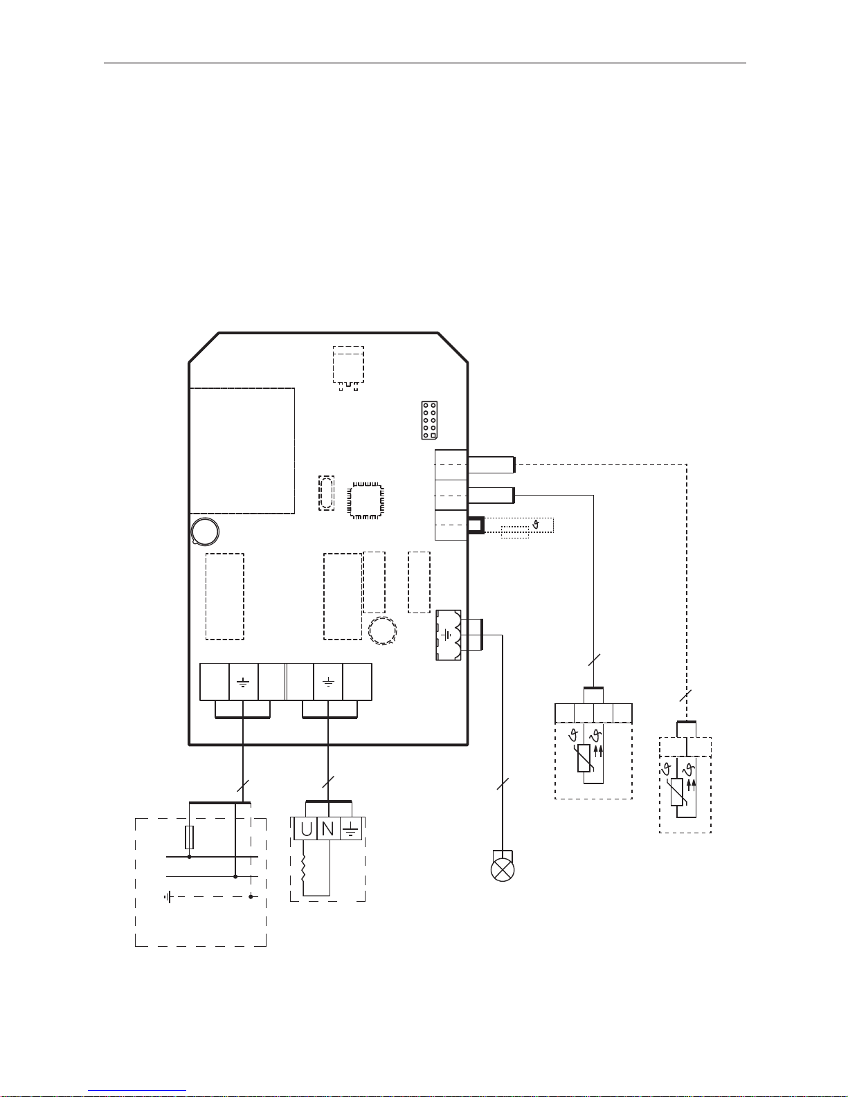
5. Elektrischer Anschluss
Bevor die Steuerung montiert wird muss der elektrische Anschluss fertiggestellt
werden. Beachten Sie beim elektrischen Anschluss folgende Punkte:
● Die Montage darf nur durch eine Elektrofachkraft oder eine vergleichsweise
qualizierte Person ausgeführt werden.
● Achten Sie darauf, dass die Anschlusskabel sauber in den Klemmen sitzen.
Schlecht geklemmte Kabel erwärmen sich stark und können zu irreparablen
Schäden und Brand führen.
N
L
PE
230V 1N ~ 50Hz
16A
3
L N
U N
3
N L
ww
r
w
3
2
wr
b
b
bb
2
max. 200W
Netz
Heizsystem
max. 3,6 kW
Licht
Raumfühler
Folienfühler
optional
WORLD OF WELLNESS
DE
Montageanweisung – nur für Fachpersonal S. 11/22
1. Führen Sie die Anschlussleitung des Raumfühlers durch die Durchführung in
der Mitte des Gehäusedeckels. Keinenfalls dürfen die Fühlerleitungen durch
die an der Unterseite vorhandenen Öffnungen geführt werden.
2. Die Zuleitung sowie die Abgänge für Heizsystem und Licht werden an der
Unterseite des Gehäuses heraus geführt.
3. Schließen Sie alle Kabel und Leitungen lt. Anschlussplan an die Steuerung an.
4. Bringen Sie die unter Punkt 4.3. Gehäuse vorbereiten auf Seite 9
gelösten Zugentlastungen wieder an.
An den mit „r“ gekennzeichneten Klemmen (Übertemperatursicherung)
bendet sich werkseitig eine Drahtbrücke. Diese muss nur dann entfernt
werden, wenn ein Temperaturfühler mit Sicherheitstemperaturbegrenzer
angeschlossen wird. Der im Lieferumfang enthaltene Fühler hat keinen
Sicherheitstemperaturbegrenzer.
Folienfühler: der Folienfühler wird nur für den Betrieb von Infrarotfolien
und Infrarot Wärmeplatten benötigt. Ist ein Folienfühler an der Steuerung angeschlossen so wird die maximale Kabinentemperatur auf 50° C
begrenzt.
An den Klemmen „b - b“ ist werkseitig ein Widerstand angebracht. Dieser
ist nur dann zu entfernen, wenn ein Folienfühler angeschlossen wird.
WORLD OF WELLNESS
Montageanweisung – nur für Fachpersonal S. 12/22
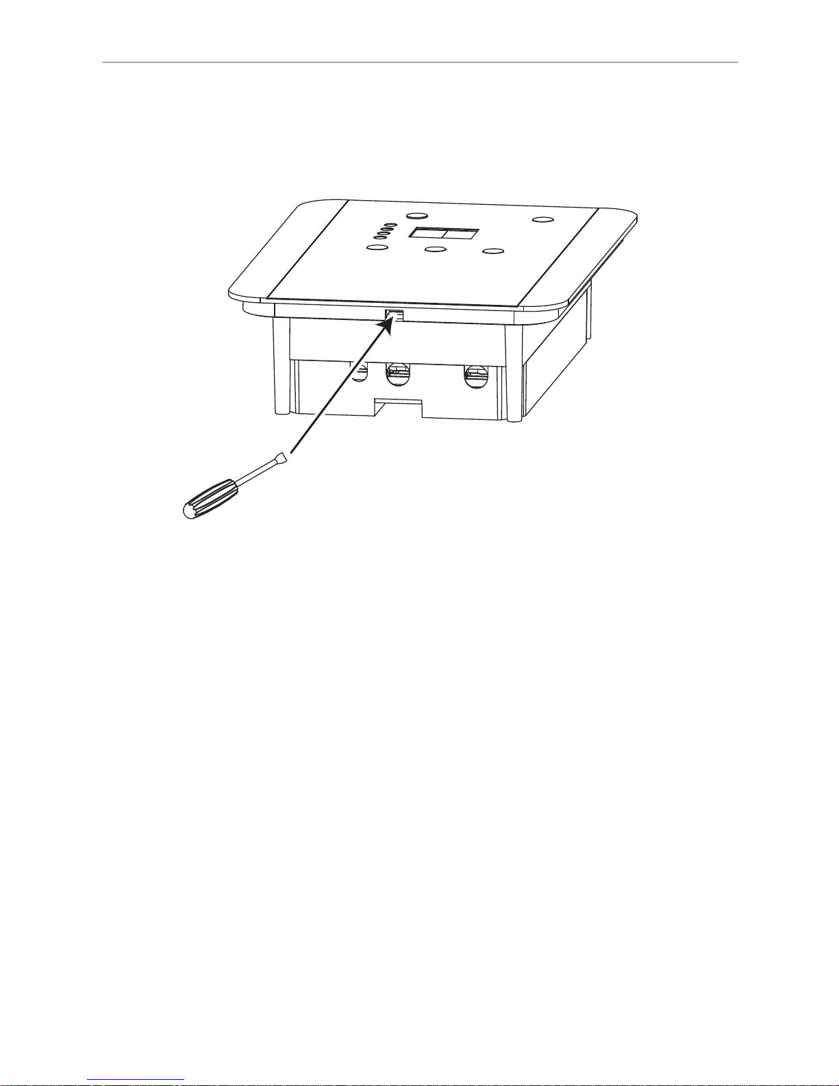
5.1. Abnehmen des vorderen Deckels
Um die Steuerung an der Wand zu befestigen muss der vordere Deckel abge-
nommen werden. Verwenden Sie dazu einen achen Schraubendreher.
Nachdem das Bedienteil an der Wand befestigt wurde, muss der Deckel wieder
aufgesetzt werden.
● Hängen Sie den Deckel zuerst an seiner Oberkante in das Steuerungsge-
häuse ein.
● Drücken Sie nun die Unterseite gegen das Gehäuse bis der Deckel wieder
einrastet.
● Führen Sie den Schraubendreher in die vorgesehene Öffnung an der Unter-
kante der Steuerung.
● Der Deckel wird von einem Schnapphaken gehalten. Drücken Sie diesen
vorsichtig nach innen bis sich der Deckel löst.
● Nehmen Sie nun den Deckel von der Steuerung ab.
WORLD OF WELLNESS
DE
Montageanweisung – nur für Fachpersonal S. 13/22
6. Endmontage
Nachdem alle elektrischen Anschlüsse hergestellt sind kann die Steuerung
montiert werden.
6.1. Endmontage - Aufputz
Zum Befestigen der Steuerung verwenden Sie die im Lieferumfang enthaltenen
50 mm Schrauben. Verwenden Sie keinenfalls Schrauben mit größeren Durchmesser. Dies kann das Gehäuse irreparabel beschädigen.
GEFAHR!
Achten Sie beim Eindrehen der Schrauben darauf, keine in der Wand
verlegten Kabel zu beschädigen. Dies kann zu schweren Personen- und
Sachschäden führen.
Arbeiten am Gehäuse dürfen nur mit einem Schraubendreher durchgeführt
werden. Bei der Verwendung eines Akkuschraubers besteht die Gefahr,
dass das Gehäuse irreparabel beschädigt wird.
WORLD OF WELLNESS
Montageanweisung – nur für Fachpersonal S. 14/22
6.2. Endmontage - versenkte Montage
Für die versenkte Montage wird die Steuerung in den Wandausschnitt gesetzt
und mit den im Lieferumfang enthaltenen 16 mm Torx-Schrauben befestigt.
GEFAHR!
Achten Sie beim Eindrehen der Schrauben darauf keine, in der Wand
verlegten Kabel zu beschädigen. Dies kann zu schweren Personen- und
Sachschäden führen.
WORLD OF WELLNESS
DE
Montageanweisung – nur für Fachpersonal S. 15/22
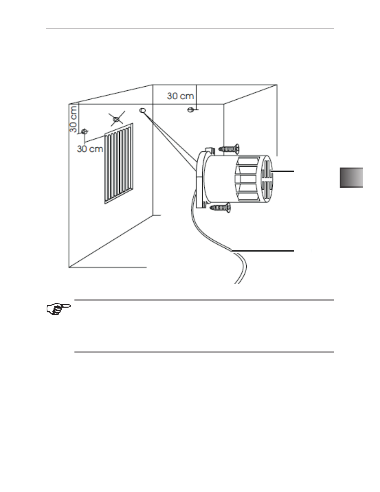
6.3. Fühlermontage
Der Raumfühler wird in der Infrarotkabine ca. 30 cm unterhalb der Decke oder
nach Angaben des Kabinen-Herstellers montiert.
● Raumfühler 1 mit den zwei beigelegten 16 mm Holzschrauben an die Ka-
binenwand schrauben.
● 2-polige Leitung 2 in der Kabinenwand verlegen und mit Leitungsschellen
xieren.
VORSICHT - Falsche Messwerte: Wird der Raumfühler zu nahe an die
Heizung montiert, kommt es zu falschen Messwerten. Einen horizontalen
Mindestabstand von ca. 30 cm zur Heizung und ca. 30 cm zur Kabinendecke einhalten. Den Raumfühler nicht über den Infrarot-Heizstäben
montieren.
1
2

WORLD OF WELLNESS
Montageanweisung – nur für Fachpersonal S. 16/22
7. Ändern der Heizzeitbegrenzung
Werkseitig ist die Heizzeitbegrenzung der Steuerung auf 99 Minuten begrenzt.
Diese kann durch setzen der nachfolgend beschriebenen Jumper auf bis zu 24
Stunden erweitert werden. Der Jumpersatz ist unter der Bestellnummer O-JUMP
als Zubehör erhältlich.
ACHTUNG!
Für den Gebrauch im privaten Bereich darf die Heizzeitbegrenzung auf
maximal 6 Stunden erweitert werden. Für Heizzeitbegrenzungen höher
als 6 Stunden sind die entsprechende Vorschriften der EN 60335-2-53
unbedingt zu beachten.
Eine minutengenaue Einstellung der Heizzeit ist nur bis zu einer Laufzeit
von 99 Minuten möglich. Ab 99 Minuten bis 9,9 Stunden ist die Laufzeit
auf 0,1 Stunden (6 Minuten) genau einstellbar. Darüberhinaus nur mehr
in 1 Stunden Schritten.
JP1
JP2
JP3
Laufzeit Jumper
99 Minuten kein
6 Stunden JP1
12 Stunden JP2
24 Stunden JP1 + JP2

WORLD OF WELLNESS
DE
Gebrauchsanweisung für den Anwender S. 17/22
8. Bedienung
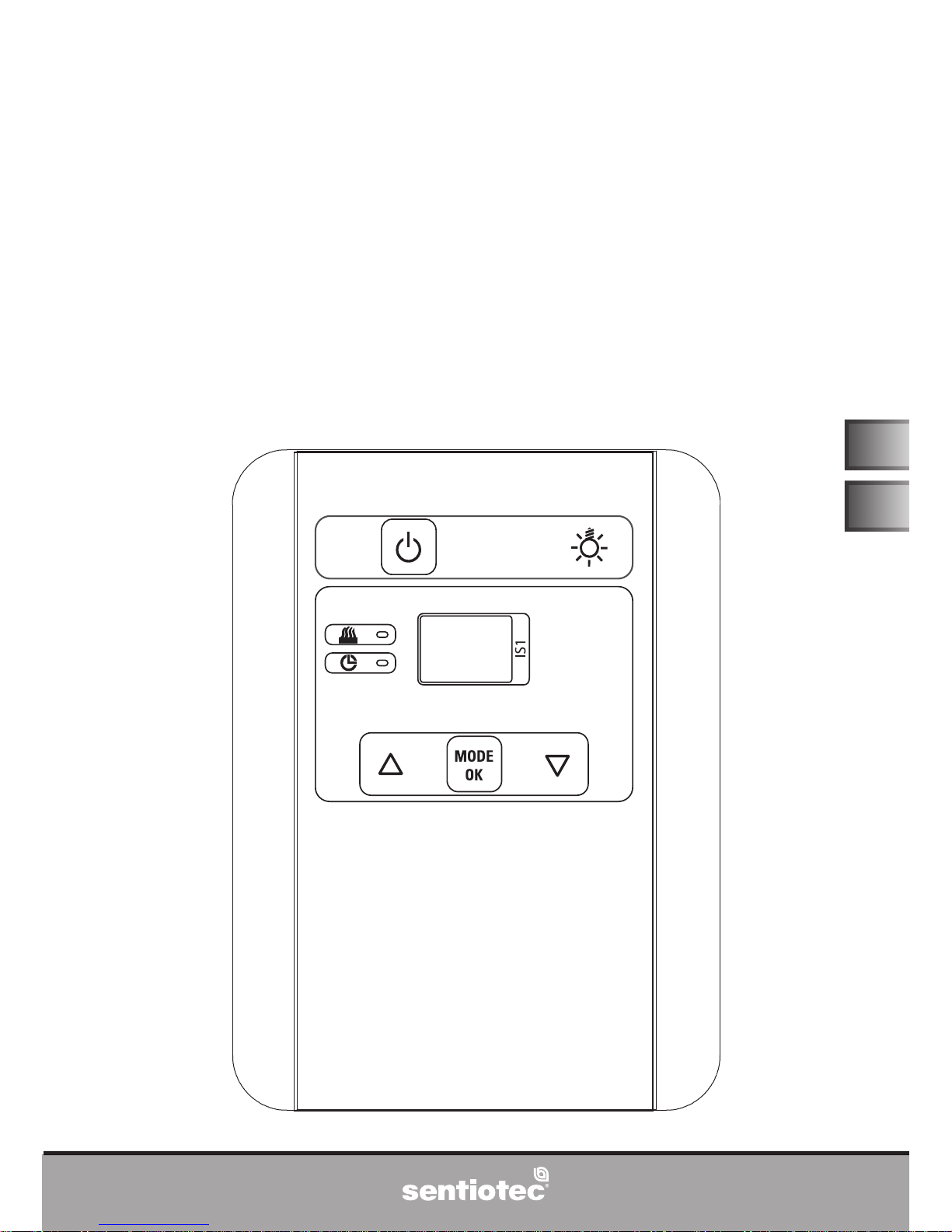
8.1. Bedien- und Anzeigeelemente
36
2
Bedienelemente:
1 Ein-/Aus-Taste
2 Licht
3 Taste +
4 Taste Mode/OK
5 Taste -
1
7
8
3
4
6
5
Anzeigeelemente:
6 Temperatur- und Laufzeitanzeige
7 Auswahl Temperatur
8 Auswahl Laufzeit
Abb. 1:Bedien- und Anzeigeelemente

WORLD OF WELLNESS
Gebrauchsanweisung für den Anwender S. 18/22
8.2. Schnellstart
● Durch drücken der Taste 1 wird die Steuerung eingeschalten.
► Im Display 6 erscheint nun die aktuelle Kabinentemperatur und die
Anzeige 7 leuchtet.
Sie können nun die Wunschtemperatur mit den Tasten 3 und 5 verändern.
Während des Einstellens blinkt die Anzeige 6.
► Bestätigen Sie die Temperatur mit der Taste 4 und das Display 6 zeigt
wieder die aktuelle Temperatur der Kabine.
● Wechseln Sie nun mit der Taste 4 auf das Uhrzeitsymbol 8.
► Mit den Tasten 3 und 5 können Sie nun die gewünschte Laufzeit
einstellen.
► Bestätigen Sie die Einstellung mit der Taste 4 oder warten Sie bis die
Steuerung die Einstellung automatisch übernimmt.
► Das Display zeigt nun die verbleibende Laufzeit an.
Hinweis: Wenn länger als 5 Sekunden keine Taste betätigt wird, übernimmt die Steuerung die Soll-Temperatur automatisch.
Hinweis: Mit der Taste 4 können Sie zwischen den Symbolen 7 und
8 wechseln. Das Display zeigt dann den jeweiligen Istwert an:
● Symbol 7: aktuelle Kabinentemperatur
● Symbol 8: verbleibende Laufzeit
Hinweis: Die Steuerung speichert die Einstellungen beim Ausschalten
durch drücken der Taste 1 ab. Wenn die Steuerung wieder mit Taste 1
eingeschalten wird, werden die letzten Einstellungen wieder aufgerufen.

WORLD OF WELLNESS
DE
Gebrauchsanweisung für den Anwender S. 19/22
8.3. Beschreibung der Funktionen und Bedienelemente
Beachten Sie Abb. 2 Bedien- und Anzeigeelemente auf Seite 17.
● Ein/Aus Taste 1
Mit dieser Taste kann die Steuerung Ein- und Ausgeschalten (Standby) werden.
Wurden bereits Laufzeit und Temperatur eingestellt, so beginnt die Steuerung
sofort mit den zuletzt getätigten Einstellungen zu arbeiten. Die Einstellungen
werden beim Wechseln in den Standby gespeichert.
● Licht Taste 2
Hier kann das Kabinenlicht zu jedem Zeitpunkt geschalten werden. Auch wenn
sich die Steuerung im Standbyzustand bendet. Das Kabinenlicht bleibt auch
nach Ende der Laufzeit eingeschalten.
● Taste + 3
Erhöht den Wert der ausgewählten Option. Wird die Taste gehalten wird der
Wert schneller erhöht. Sobald die Taste gedrückt wurde beginnt die Anzeige zu
blinken und der Sollwert wird angezeigt.
● Taste Mode/OK 4
Mit dieser Taste können Sie zwischen der Temperatur und Laufzeitanzeige
wechseln. Es wird der aktuelle Istwert angezeigt. Desweiteren dient diese Taste
auch zum Bestätigen des Sollwertes.
● Taste - 5
Verringert den Wert der ausgwählten Option. Wird die Taste gehalten wird der
Wert schneller erhöht. Sobald die Taste gedrückt wurde beginnt die Anzeige zu
blinken und der Sollwert wird angezeigt.
● Temperatur- und Laufzeitanzeige 6
Leuchtet die Anzeige dauerhaft so wird der jewelige Istwert angezeigt. Der Sollwert wird dargestellt wenn eine der Tasten, 3 oder 5, gedrückt wurde. Die
Anzeige blinkt solange bis die Taste 4 gedrückt wurde oder die Einstellung
automatisch nach 5 Sekunden übernommen wird. Danach leuchtet die Anzeige
wieder dauerhaft und der Istwert wird wieder angezeigt.

WORLD OF WELLNESS
Gebrauchsanweisung für den Anwender S. 20/22
● Auswahl Temperatur 7
Hier kann die gewünschte Temperatur eingestellt werden. Die Einstellung wird
mit den Tasten 3 und 5 vorgenommen. Solange die Solltemperatur angezeigt
wird blinkt die Anzeige 6. Sie können nun den eingestellten Wert mit 4 bestätigen oder warten bis nach 5 Sekunden der Wert automatisch übernommen wird.
► Minimalwert: 30° C
► Maximalwert: 70° C bei Strahlerbetrieb, 50° C bei Folienbetrieb
● Auswahl Laufzeit 8
Hier kann die gewünschte Laufzeit eingestellt werden. Die Einstellung wird mit den
Tasten 3 und 5 vorgenommen. Solange die gewünschte Laufzeit angezeigt
wird blinkt die Anzeige 6. Sie können nun den eingestellten Wert mit 4 bestätigen oder warten bis nach 5 Sekunden der Wert automatisch übernommen wird.
Hinweis: Die maximale Laufzeit wird durch die Heizzeitbegrenzung
limitiert. Siehe auch 7. Ändern der Heizzeitbegrenzung auf Seite 16.
Laufzeit Einstellgenauigkeit
< 99 Minuten 1 Minute
99 Minuten - 9,9 Stunden 0,1 Stunden (6 Minuten)
> 9,9 Stunden 1 Stunde

WORLD OF WELLNESS
DE
Montage- und Gebrauchsanweisung S. 21/22
9. Problemlösung
Die Infrarotsteuerung ist mit einer Diagnose-Software ausgestattet, die beim
Einschalten und im Betrieb die Systemzustände überprüft. Sobald die Diagnosesoftware einen Fehler erkennt, schaltet die Infrarotsteuerung das Heizsystem ab.
Fehler Beschreibung Ursache / Behebung
E1 Sicherheitstemperatur-
begrenzer
Der im Lieferumfang enthaltene Fühler
hat keinen Sicherheitstemperaturbegrenzer. Überprüfen Sie den Sitz der
werkseitig angebrachten Drahtbrücke.
E3 Raumfühler Unterbre-
chung
Überprüfen Sie die Kabel des Kabinenfühlers auf Schadstellen und die Klemmstellen auf korrekten Sitz
E4 Raumfühler Kurzschluss Überprüfen Sie das Kabel des Kabinen-
fühlers auf Schadstellen.
E5 Folienfühler Unterbrech-
nung
Wenn Sie keine Folien oder Wärmeplatten verwenden muss der werkseitige
Dummyfühler in seiner Position verbleiben.
Wenn Sie einen Folienfühler verwenden,
kontrollieren Sie das Kabel auf Schadstellen und die Klemmen auf korrekten
Sitz.
E6 Folienfühler Kurzschluss Wenn Sie einen Folienfühler verwenden,
kontrollieren Sie das Kabel auf Schadstellen und die Klemmen auf korrekten Sitz.
E7 Übertemperatur Folie Wenn Sie keine Folien oder Wärmeplat-
ten verwenden muss der werkseitige
Dummyfühler in seiner Position verbleiben.
Wenn Sie einen Folienfühler verwenden,
kontrollieren Sie das Kabel auf Schadstellen und die Klemmen auf korrekten
Sitz.
► Sollte sich der Fehler durch die oben beschriebenen Maßnamen
nicht abstellen lassen, so kontaktieren Sie Ihren Lieferanten.

WORLD OF WELLNESS
10. Entsorgung
● Entsorgen Sie die Verpackungsmaterialien nach den gültigen
Entsorgungsrichtlinien.
● Altgeräte enthalten wiederverwendbare Materialien, aber auch
schädliche Stoffe. Geben Sie Ihr Altgerät deshalb auf keinen Fall
in den Restmüll, sondern entsorgen Sie das Gerät nach den örtlich
geltenden Vorschriften.
11. Technische Daten
Allgemein
Stromversorgung: 230 V AC ~ 1N PE
Maximale Schaltlast Heizsystem: 16 A, 3,6 kW
Maximale Schaltlast Licht: 0,8 A
Leistungsaufnahme Betrieb: 3 W
Leistungsaufnahme Stand-By: 1 W
Umgebungsbedienungen
Umgebungstemperatur: 0° C - 70° C
Luftfeuchte: max. 99% rel.
36
99
179,5
134,5
158
39,5
48,5

Version 11/14 Ident no. 50950078
INSTRUCTIONS FOR INSTALLATION AND USE
English
EN
36
Infrared control unit
IS1
P-IS1-T

WORLD OF WELLNESS
Table of Contents
1. About this instruction manual 3
2. Important information for your safety 4
2.1. Intended use 4
2.2. Safety information for the installer 5
2.3. Safety information for the user 6
3. Product description 7
3.1. Scope of delivery 7
3.2. Optional accessories 7
3.3. Product functions 7
4. Installation 8
4.1. Preparing for surface mounting 8
4.2. Preparing for recess mounting 9
4.3. Preparing the housing 9
5. Electrical connection 10
5.1. Removing the front cover 12
6. Final assembly 13
6.1. Final assembly - surface mounting 13
6.2. Final assembly - recess mounting 14
6.3. Fitting the sensor 15
7. Adjusting the heating time limit 16
8. Operation 17
8.1. Operating and display elements 17
8.2. Quick start 18
8.3. Description of the functions and control elements 19
9. Troubleshooting 21
10. Disposal 22
11. Technical data 22

WORLD OF WELLNESS
EN
Instructions for installation and use p. 3/22
1. About this instruction manual
Read these installation and operating instructions carefully and keep them within
reach when using the infrared control unit. This ensures you can refer to information about safety and operation at any time.
Symbols used for warnings
These installation and operating instructions feature warning symbols next to
activities presenting a hazard to the user. Warning symbols must be observed
at all times. This prevents damage to property and injuries, which in the worst
case may be fatal.
The warning symbols contain keywords with the following meanings:
DANGER!
Serious or fatal injury will occur if this warning symbol is not observed.
WARNING!
Serious or fatal injury may occur if this warning symbol is not observe.
CAUTION!
Minor injuries may occur if this warning symbol is not observed.
ATTENTION!
This keyword is a warning that damage to property may occur.
Other symbols
This symbol indicates tips and useful information.
The current installation and operating instructions can also be found in
the downloads section of our website: www.sentiotec.com/downloads.

WORLD OF WELLNESS
Instructions for installation and use p. 4/22
2. Important information for your safety
The IS1 infrared control unit has been produced in accordance
with the safety regulations applicable for technical units. However,
hazards may occur during use. You should therefore adhere to
the following safety information and the specic warnings in the
individual chapters.
2.1. Intended use
The IS1 infrared control unit is used to control and regulate the
interior temperature and to operate the cabin light. The infrared
control unit may only be used for controlling one heating circuit with
a maximum capacity of 3.6 kW.
Suitable infrared heaters: DIR-350-R, WIR-350-R, DIR-500-R,
WIR-500-R, DIR-750-R, WIR-750-R, DIR-1300-R, WIR-1300-R,
ECO-350-R, ECO-350-G, ECO-500-R, ECO-500-G, ECO-750-R,
O-IRC-W
Suitable infrared plates: IR-WP-175, IR-WP-100, IR-WP-390, IRWP-510, IR-WPHL-510, IR-WPHL-100, IR-WPHL-390, IR-WPHL-175
► Only in connection with the optional P-ISX-FF foil sensor.
Any use exceeding this scope is considered improper. Improper
use can result in damage to the product, severe injuries or death.

WORLD OF WELLNESS
EN
Instructions for installation and use p. 5/22
2.2. Safety information for the installer
● Installation may only be performed by a qualied electrician or
similarly qualied person.
● Installation and connection of the infrared control unit may only
be performed when the power supply is disconnected.
● The temperature sensor must be mounted in such a way that
ensures it is unaffected by the inow of air.
● Observe all regulations applicable at the installation location.
● For your own safety, consult your supplier in the event of prob-
lems that are not explained in sufcient detail in the installation
instructions.

WORLD OF WELLNESS
Instructions for installation and use p. 6/22
2.3. Safety information for the user
● The device must not be used by children under 8 years old.
● The device may only be used by children over 8 years old, by
persons with limited psychological, sensory or mental capabilities or by persons with lack of experience/knowledge under the
following conditions:
– When they are supervised.
– When they have been shown how to use the device safely
and are aware of the hazards that could occur.
● Children must not play with the device.
● Children under 14 years old may only clean the device if they
are supervised.
● For health reasons, do not use the infrared cabin if you are under
the inuence of alcohol, medication or drugs.
● Make sure that no ammable objects have been placed on or
in front of the infrared heater or infrared heat plate before the
infrared control unit is switched on.
● For your own safety, consult your supplier in the event of prob-
lems that are not described in sufcient detail in the operating
instructions.

WORLD OF WELLNESS
EN
Instructions for installation and use p. 7/22
3. Product description
3.1. Scope of delivery
● IS1 infrared control unit
● 1.6 m mains connection cable
● 1.5 m room sensor with silicone cable
● Installation material
● Instructions for installation and use
3.2. Optional accessories
● IR-IS-A03 Adapter cable for heaters and heat plates (0.3 m)
● IR-IS-A25 Adapter cable for heaters and heat plates (2.5 m)
● IR-1P2 T-splitter, 2-way
● IR-1P3 Splitter, 3-way
● IR-1P5 Splitter, 5-way
● P-ISX-FF Foil sensor incl. 3 m cable
● P-ISX-FUSE Fine fuse connection for light
● O-F2 Room sensor
3.3. Product functions
The IS1 infrared control unit is used to regulate the cabin temperature using a
room sensor. Settings can be made for the target temperature, duration and light
using the operating elements. The current temperature is shown on the display.
1 heating circuit for a max. capacity of 3.6 kW enables the connection of infrared
heaters and infrared heat plates.

WORLD OF WELLNESS
Installation instructions, only for experts p. 8/22
4. Installation
The infrared control unit can either be surface-mounted or recess mounted.
4.1. Preparing for surface mounting
To mount the control unit on a surface, you need to make cable bushings in the
cabin wall. Refer to the following gure for the positions.
49
85
17,5
34
49
65
80,5
1
7
2 3 4 5 6
1 Sensor cable outlet
2 Mains power line
3 Heater/foils outlet
4 Free
5 Free
6 Light outlet
7 Cable shaft
► Caution: If the cable is fed down-
wards through the cable shaft 7, the
sensor cable must be tted with additional protective insulation.

WORLD OF WELLNESS
EN
Installation instructions, only for experts p. 9/22
4.2. Preparing for recess mounting
Mounting the control unit in a recess requires a cut-out section.
● Cut-out section size: 160 mm x 102 mm
● Mounting depth: 39.5 mm
4.3. Preparing the housing
102 mm
160 mm
R=5 mm
► Ensure that the control unit
has sufcient rear ventilation!
Work on the housing must only be carried out using a standard screwdriver. Using a cordless screwdriver may cause irreparable damage to
the housing.
● Remove the four screws in the housing 1.
● Take the cover 2 off the control unit.
● Loosen the strain reliefs 3.
1
2
3

WORLD OF WELLNESS
Installation instructions, only for experts p. 10/22
5. Electrical connection
Before mounting the control unit, the electrical connections must be completed.
Observe the following points when connecting the power:
● Installation may only be performed by a qualied electrician or similarly quali-
ed person.
● Make sure that the connection cables are properly tted in the terminals. Poorly
tted cables heat up quickly and can result in irreparable damage and re.
N
L
PE
230V 1N ~ 50Hz
16A
3
L N
U N
3
N L
ww
r
w
3
2
wr
b
b
bb
2
max. 200W
Mains
Heating system
max. 3.6 kW
Light
Room sensor
Optional foil
sensor

WORLD OF WELLNESS
EN
Installation instructions, only for experts p. 11/22
1. Guide the connection cable for the room sensor through the cable bushing
in the middle of the housing cover. Do not, under any circumstances, guide
the sensor cables through the existing openings at the bottom.
2. The inlet and outlet for the heating system and lighting are fed out at the
bottom of the housing.
3. Connect all cables and lines to the control unit according to the connection
diagram.
4. Reattach the strain reliefs which were loosened under point 4.3. Preparing
the housing on page 9.
There is an ex-works wire jumper at the terminal marked “r” (excess
temperature). This should only be removed if a temperature sensor with
safety temperature limiter is connected. The sensor included in the delivery does not have a safety temperature limiter.
Foil sensor: the foil sensor is only required for the operation of infrared
foils and infrared heat plates. If a foil sensor is connected to the control
unit, the maximum cabin temperature is limited to 50° C.
At the “b - b” terminals, a resistor is tted ex-works. This may only be
removed if a foil sensor is connected.

WORLD OF WELLNESS
Installation instructions, only for experts p. 12/22
5.1. Removing the front cover
The front cover must be removed to mount the controller on the wall. To do this,
use a at screwdriver.
Once the control module has been mounted on the wall, replace the cover.
● First t the upper edge of the cover into the control unit housing.
● Then press the bottom against the housing until the cover clicks into place
again.
● Insert the screwdriver into the hole provided at the bottom edge of the control
unit.
● The cover is held on by a clip. Press this inwards carefully until the cover
loosens.
● Now remove the cover from the control unit.

WORLD OF WELLNESS
EN
Installation instructions, only for experts p. 13/22
6. Final assembly
After all the electrical connections have been made, the control unit can be
mounted.
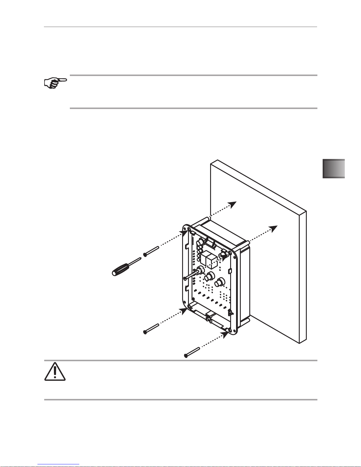
6.1. Final assembly - surface mounting
To attach the control unit, use the 50 mm screws included in the delivery. Do not
use screws with a larger diameter. This could damage the housing irreparably.
DANGER!
When tightening the screws, be careful not to damage any cables in the
wall. This can lead to severe damage and injury.
Work on the housing must only be carried out with a screwdriver. Using
a cordless screwdriver may cause irreparable damage to the housing.

WORLD OF WELLNESS
Installation instructions, only for experts p. 14/22
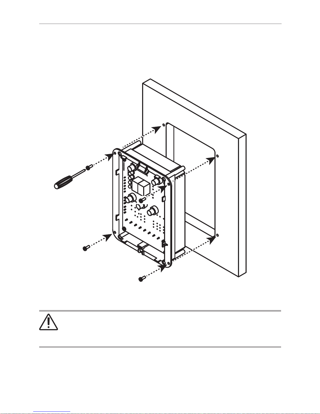
6.2. Final assembly - recess mounting
For recess mounting the control unit is placed in a wall cut-out section and attached using the 16 mm Torx screws included.
DANGER!
When tightening the screws, be careful not to damage any cables in the
wall. This can lead to severe damage and injury.

WORLD OF WELLNESS
EN
Installation instructions, only for experts p. 15/22
6.3. Fitting the sensor
The room sensor is tted in the infrared cabin about 30 cm below the ceiling or
according to the cabin manufacturer's instructions.
● Attach room sensor 1 to the cabin wall using the two 16 mm wood screws
included.
● Lay the 2-pin cable 2 in the cabin wall and secure with cable ties.
CAUTION - incorrect readings: If the room sensor is tted too near
the heater, it will produce incorrect measured values. Maintain a minimum horizontal distance of approx. 30 cm to the heater and approx.
30 cm to the cabin ceiling. Do not t the room sensor above the infrared
heating rods.
1
2

WORLD OF WELLNESS
Installation instructions, only for experts p. 16/22
7. Adjusting the heating time limit
The heating time limit for the control unit is set at the factory to 99 minutes. This
can be extended up to 24 hours by setting the jumper as described below. The
jumper set is available as an accessory under the order number O-JUMP.
ATTENTION!
For domestic use, the heating time limit may be extended to a maximum
of 6 hours. The provisions of EN 60335-2-53 must be observed for heating time limits of more than 6 hours.
Heating time settings can only be made to the exact minute for operating
times of up to 99 minutes. From 99 minutes to 9.9 hours, the operating
time can be set with a precision of 0.1 of an hours (6 minutes). After this,
only in 1 hour increments.
JP1
JP2
JP3
Operating time Jumper
99 minutes none
6 hours JP1
12 hours JP2
24 hours JP1 + JP2

WORLD OF WELLNESS
EN
Instructions for use for the user p. 17/22
8. Operation
8.1. Operating and display elements
36
2
Operating elements:
1 On/Off button
2 Light
3 + button
4 Mode/OK button
5 - button
1
7
8
3
4
6
5
Display elements:
6 Temperature and operating time
display
7 Temperature selection
8 Operating time selection
Fig. 1:Operating and display elements

WORLD OF WELLNESS
Instructions for use for the user p. 18/22
8.2. Quick start
● Press button 1 to switch on the control unit.
► The current cabin temperature appears in display 6 and display 7 lights up.
You can adjust the required temperature with buttons 3 and 5. While you are
making the setting, display 6ashes.
► Press button 4 to conrm the temperature and display 6 indicates the
current temperature in the cabin.
● Now press button 4 to switch to the time symbol 8.
► Press buttons 3 and 5 to set the required operating time.
► Press button 4 to conrm the setting or wait until the control unit makes
the setting automatically.
► The display now shows the remaining operating time.
Note: If no button is pressed for more than 5 seconds, the control unit
automatically uses the target temperature.
Note: Press button 4 to switch between the symbols 7and 8. The display
then shows the respective value:
● Symbol 7: current cabin temperature
● Symbol 8: remaining operating time
Note: Press button 1 to enable the control unit to save the settings when
switched off. When the control unit is switched on again with button 1 the
previous settings are retrieved again.

WORLD OF WELLNESS
EN
Instructions for use for the user p. 19/22
8.3. Description of the functions and control elements
Observe Fig. 1:Operating and display elements on page 17.
● On/Off button 1
Use this button to switch the control unit on and off (standby). If the operating
time and temperature have already been set, the control units starts immediately
with the previously selected settings. The settings are saved when switching to
standby.
● Light button 2
Here you can switch on the cabin light at any time. even if the control unit is
in standby. The cabin light also stays on once the operating time has elapsed.
● + button 3
Press this button to increase the value of the selected option. Hold down the
button to increase the value more quickly. As soon as you press the button, the
display begins to ash and the target value is shown.
● Mode/OK button 4
You can switch between the displays for temperature and the operating time
with this button. The current value is displayed. You can also press this button
to conrm the target value.
● - button 5
Press this button to decrease the value of the selected option. Hold down the
button to increase the value more quickly. As soon as you press the button, the
display begins to ash and the target value is shown.
● Temperature and duration display 6
When the display is lit up permanently it shows the respective current value. The
target value is displayed when you press button 3 or 5. The display ashes until
you press button 4 or the value is set automatically after 5 seconds. Then the
display is lit up permanently and the actual value is shown again.

WORLD OF WELLNESS
Instructions for use for the user p. 20/22
● Temperature selector 7
Here you can set the required temperature. Press buttons 3 and 5 to make the
setting. While the target temperature is being displayed, display 6 ashes. You
can now conrm the set value by pressing 4 or wait 5 seconds until the value is
set automatically.
► Minimum value: 30° C
► Maximum value: 70° C for heater mode, 50° C for foil mode
● Operating time selection 8
Here you can set the required operating time. Press buttons 3 and 5 to make the
setting. While the required operating time is being displayed, display 6 ashes.
You can now conrm the set value by pressing 4 or wait 5 seconds until the value
is set automatically.
Note: The maximum operating time is restricted by the heating time limit.
See also 7. Adjusting the heating time limit on page 16.
Operating time Setting precision
< 99 minutes 1 minute
99 minutes - 9.9 hours 0.1 hours (6 minutes)
> 9.9 hours 1 hour

WORLD OF WELLNESS
EN
Instructions for installation and use p. 21/22
9. Troubleshooting
The infrared control unit is equipped with diagnostic software which monitors the
system status when switching on and during operation. As soon as the diagnostic
software identies an error, the infrared control unit switches the heating system off.
Error Description Cause / rectication
E1 Safety temperature
limiter
The sensor included in the delivery does
not have a safety temperature limiter.
Check that the ex-works wire jumper is
secure.
E3 Room sensor interruption Check the cabin sensor cable for dam-
age and that the terminal points are connected properly
E4 Room sensor short-
circuit
Check the cabin sensor cable for damage.
E5 Foil sensor interruption If you are not using foils or heating plates,
the ex-works dummy sensor must stay
in position.
If you are using a foil sensor, check the
cable for damage and check that the terminals are connected properly.
E6 Foil sensor short-circuit If you are using a foil sensor, check the
cable for damage and check that the terminals are connected properly.
E7 Foil excess temperature If you are not using foils or heating plates,
the ex-works dummy sensor must stay
in position.
If you are using a foil sensor, check the
cable for damage and check that the terminals are connected properly.
► If the error still persists despite performing the measures described
above, please contact your supplier.

WORLD OF WELLNESS
10. Disposal
● Dispose of packaging materials in accordance with the applicable
disposal regulations.
● Used devices contain reusable materials, as well as hazardous
substances. Do not dispose of your used device with household
waste, but do so in accordance with the locally applicable regulations.
11. Technical data
General information
Power supply: 230 V AC ~ 1N PE
Maximum switching load of the heating system: 16 A, 3.6 kW
Maximum switching load of the light: 0.8 A
Power consumption of the operation: 3 W
Power consumption of the standby: 1 W
Ambient conditions
Ambient temperature: 0° C - 70° C
Air humidity: max. 99% rel.
36
99
179,5
134,5
158
39,5
48,5

WORLD OF WELLNESS
NOTIZEN / APPUNTI / NOTES / NOTE / NOTITIES
………………………………………………….............………………………………………………………………...
…………………………………………………………….......……………………………………………………………...
…………………………………………………………….............………………………………………………………...
…………………………………………………….............………………………………………………………………...
……………………………………………………………......……………………………………………………………...
……………………………………………………………......……………………………………………………………...
……………………………………………………………..........…………………………………………………………...
…………………………………………………………….............………………………………………………………...
…………………………………………………………….............………………………………………………………...
…………………………………………………………….............………………………………………………………...
…………………………………………………………….............………………………………………………………...
…………………………………………………………….............………………………………………………………...
.…………………………………………………………….............………………………………………………………...
…………………………………………………………….............………………………………………………………...
…………………………………………………………….............………………………………………………………...
…………………………………………………………….............………………………………………………………...
…………………………………………………………….............………………………………………………………...
…………………………………………………………….............………………………………………………………...
…………………………………………………………….............………………………………………………………...

sentiotec GmbH world of wellness Oberregauer Straße 48 4844 Regau, Austria
T +43 (0) 7672/277 20-800 F +43 (0) 7672/277 20-801
E info@sentiotec.com www.sentiotec.com
 Loading...