


Saunasteuerung
Saunasteuerung CK 3
Montageanweisung
Gebrauchsanweisung
CK 31
O-CK31
MONTAGE- UND GEBRAUCHSANWEISUNG
Deutsch
AUTOMATIC
DRY
SAUNA
CLIMA
VENT
CLIMA
DE
EN
Version 04/19 Ident-Nr. 1-021-752

Inhaltsverzeichnis
1. Zu dieser Anleitung 4
2. Wichtige Hinweise zu Ihrer Sicherheit 5
2.1. Bestimmungsgemäßer Gebrauch 5
2.2. Sicherheitshinweise für den Monteur 6
2.3. Sicherheitshinweise für den Anwender 7
3. Produktbeschreibung 8
3.1. Lieferumfang 8
3.2. Optionales Zubehör 8
3.3. Produktfunktionen 8
3.4. Sauna-Betriebsarten 9
3.5. Fühler-Betriebsarten 10
4. Montage 11
4.1. Saunasteuerung montieren 11
4.2. Ofenfühler F1 mit Übertemperatur-Sicherung montieren 12
4.3. Bankfühler F2 (optional) montieren 13
4.4. Feuchte-Temperaturfühler FTS2 (optional) montieren 13
5. Elektrischer Anschluss 14
5.1. Versorgungsleitung, Ofen anschließen 14
5.2. Verdampfer anschließen 15
5.3. Licht anschließen 15
5.4. Lüfter (optional) anschließen 15
5.5. Optionale Leistungserweiterung anschließen 15
5.6. Ofenfühler F1 anschließen 15
5.7. Bankfühler F2 (optional) anschließen 16
5.8. Feuchte-Temperaturfühler FTS2 (optional) anschließen 16
5.9. Installation abschließen 16
6. Prüfungen durchführen 17

Inhaltsverzeichnis
7. Inbetriebnahme 18
7.1. Heizzeitbegrenzung einstellen 18
7.2. Einstellungen im Optionsmenü 19
8. Bedienung 20
8.1. Licht einschalten 20
8.2. Saunasteuerung einschalten 20
8.3. Einstellmöglichkeiten 21
8.4. Menüpunkte anwählen 22
8.5. Uhrzeit eingeben 23
8.6. Sauna - Betrieb: Manueller Betrieb - Schnell-Start 24
8.7. Sauna - Betrieb: Automatik-Betrieb 26
8.8. Clima Betrieb: Manueller Betrieb - Schnell-Start 31
8.9. Clima Betrieb: Automatic 33
8.10. Wasserstandskontrolle 36
8.11. Automatisches Kabinen-Nachtrocknungs-Programm 37
8.12. Bei längeren Betriebspausen 37
8.13. Voreinstellungen 37
9. Problemlösung 38
9.1. Innenraumbeleuchtung leuchtet nicht 38
9.2. Batterie für Uhr wechseln 38
9.3. Sicherungen wechseln 38
9.4. Fehlermeldungen 39
9.5. Meldungen in der Anzeige 40
10. Reinigung 41
11. Wartung 41
12. Entsorgung 41
13. Technische Daten 42
Montage- und Gebrauchsanweisung S. 4/44
1. Zu dieser Anleitung
Lesen Sie diese Montage- und Gebrauchsanweisung gut durch und bewahren Sie
sie in der Nähe der Saunasteuerung auf. So können Sie jederzeit Informationen
zu Ihrer Sicherheit und zur Bedienung nachlesen.
Sie nden diese Montage- und Gebrauchsanweisung auch im Download-
bereich unserer Webseite auf www.sentiotec.com/downloads.
Symbole in Warnhinweisen
In dieser Montage- und Gebrauchsanweisung ist vor Tätigkeiten, von denen eine
Gefahr ausgeht, ein Warnhinweis angebracht. Befolgen Sie diese Warnhinweise
unbedingt. So vermeiden Sie Sachschäden und Verletzungen, die im schlimmsten
Fall sogar tödliche sein können.
In den Warnhinweisen werden Signalwörter verwendet, die folgende Bedeutungen haben:
GEFAHR!
Wenn Sie diesen Warnhinweis nicht beachten, sind Tod oder schwere
Verletzungen die Folge.
WARNUNG!
Wenn Sie diesen Warnhinweis nicht beachten, können Tod oder schwere
Verletzungen die Folge sein.
VORSICHT!
Wenn Sie diesen Warnhinweis nicht befolgen, können leichte Verletzungen die Folge sein.
ACHTUNG!
Dieses Signalwort warnt Sie vor Sachschäden.
Andere Symbole
Dieses Symbol kennzeichnet Tipps und nützliche Hinweise.

Montage- und Gebrauchsanweisung S. 5/44
2. Wichtige Hinweise zu Ihrer Sicherheit
Die Saunasteuerung CK 31 ist nach anerkannten sicherheitstechnischen Regeln gebaut. Dennoch können bei der Verwendung
Gefahren entstehen. Befolgen Sie deshalb die folgenden Sicherheitshinweise und die speziellen Warnhinweise in den einzelnen
Kapiteln. Beachten Sie auch die Sicherheitshinweise der angeschlossenen Geräte.
2.1. Bestimmungsgemäßer Gebrauch
Die Saunasteuerung CK 31 dient ausschließlich zum Steuern und
Regeln der Funktionen gemäß den technischen Daten.
Die Saunasteuerung CK 31 darf nur zum Steuern und Regeln von
3 Heizkreisen mit maximal 3,5 kW Heizleistung pro Heizkreis eingesetzt werden. Die maximale Verdampferleistung beträgt 3,5 kW.
Jeder darüber hinausgehende Gebrauch gilt als nicht bestimmungsgemäß. Nicht bestimmungsgemäßer Gebrauch kann zur Beschädigung des Produkts, zu schweren Verletzungen oder Tod führen.
DE

Montage- und Gebrauchsanweisung S. 6/44
2.2. Sicherheitshinweise für den Monteur
● Die Montage darf nur durch eine Elektrofachkraft oder eine ver-
gleichsweise qualizierte Person ausgeführt werden. Arbeiten
an der Saunasteuerung dürfen nur im spannungsfreien Zustand
durchgeführt werden.
● Es ist bauseits eine allpolige Trennvorrichtung mit voller Abschal-
tung entsprechend der Überspannungskategorie III vorzusehen.
● Die Saunasteuerung ist außerhalb der Saunakabine in ca. 1,70 m
Höhe oder gemäß den Empfehlungen des Kabinenherstellers
zu montieren. Die Umgebungstemperatur muss im Bereich von
-10 °C und 40 °C liegen.
● Der Ofenfühler ist so anzubringen, dass er nicht durch einströ-
mende Luft beeinusst wird.
● Die Ofen-Zuleitung muss einen Querschnitt von mindestens
2,5 mm2 aufweisen und bis 150 °C temperaturbeständig sein.
● Beachten Sie auch die örtlichen Bestimmungen am Aufstellort.
● Bei Problemen, die in den Montageanweisungen nicht ausführ-
lich genug behandelt werden, wenden Sie sich zu Ihrer eigenen
Sicherheit an Ihren Lieferanten.

Montage- und Gebrauchsanweisung S. 7/44
2.3. Sicherheitshinweise für den Anwender
● Die Saunasteuerung darf nicht von Kindern unter 8 Jahren ver-
wendet werden.
● Die Saunasteuerung darf von Kindern über 8 Jahren, von Perso-
nen mit verringerten psychischen, sensorischen oder mentalen
Fähigkeiten und von Personen mit Mangel an Erfahrung und
Wissen unter folgenden Bedingungen verwendet werden:
– wenn sie beaufsichtigt werden
– wenn ihnen die sichere Verwendung gezeigt wurde und sie
die Gefahren, die entstehen können, verstehen.
● Kinder dürfen nicht mit der Saunasteuerung spielen.
● Kinder unter 14 Jahren dürfen die Saunasteuerung nur reinigen,
wenn sie beaufsichtigt werden.
● Wenn Sie unter dem Einuss von Alkohol, Medikamenten oder
Drogen stehen, verzichten Sie aus gesundheitlichen Gründen
auf das Saunabad.
● Stellen Sie sicher, dass keine brennbaren Gegenstände auf dem
Saunaofen liegen, bevor Sie die Saunasteuerung einschalten.
● Stellen Sie sicher, dass keine brennbaren Gegenstände auf dem
Saunaofen liegen, bevor Sie die Vorwahlzeitfunktion aktivieren.
● Bei Problemen, die in der Gebrauchsanweisung nicht ausführ-
lich genug behandelt werden, wenden Sie sich zu Ihrer eigenen
Sicherheit an Ihren Lieferanten.
DE
Montage- und Gebrauchsanweisung S. 8/44
3. Produktbeschreibung
3.1. Lieferumfang
● Saunasteuerung
● Ofenfühler mit integrierter Übertemperatur-Sicherung (F1)
● Fühlerleitungen
● Montagematerial
3.2. Optionales Zubehör
● Bankfühler (Artikelnummer: O-F2)
● Feuchte-Temperaturfühler (Artikelnummer: O-FTS2)
● Leistungserweiterung (Artikelnummer: O-S2-18 / O-S2-30)
● Sicherheitsabschaltung (Artikelnummer: HT-SWL)
HINWEIS - Optionales Zubehör:
Der Fühler F2 oder alternativ der Feuchte-Temperatur-Sensor FTS 2
muss separat bestellt werden, da sonst die Sauna Steuerung nicht
funktionsfähig ist.
3.3. Produktfunktionen
Die Saunasteuerung CK 31 verfügt über folgende Funktionen:
● Regeln von Kombi-Saunaöfen mit einer Heizleistung bis 10,5 kW und einer
Verdampferleistung bis 3,5 kW.
● Mit einer Leistungserweiterung kann die maximale Schaltleistung von 10,5 kW
auf 18 kW oder 30 kW erhöht werden.
● Intensitätsregelung eines Lüfters (bis 100 W)
● Vorwahlzeitfunktion (bis 23 Stunden 59 Minuten)
● Automatische Heizzeitbegrenzung
Die Saunasteuerung schaltet sich nach Ablauf der maximalen Heizzeit aus
Sicherheitsgründen automatisch ab. Die maximale Heizzeit kann auf 6 h,
12 h, 18 h oder 24 h eingestellt werden.

Montage- und Gebrauchsanweisung S. 9/44
● Nachtrockenprogramm
Nach Beendigung des Clima-Betriebes wird das Nachtrockenprogramm automatisch gestartet, um Schimmel- und Fäulnisbildung in der Saunakabine
zu verhindern. Die Nachtrockenphase kann bis zu 85 Minuten dauern, die
Kabinentemperatur wird geregelt, und der Lüfter läuft mit unterschiedlichen
Drehzahlen.
● Übertemperatur-Sicherung
Die Übertemperatur-Sicherung bendet sich im Fühlergehäuse des Ofenfühlers.
Wenn der Saunaofen durch einen Defekt nach Erreichen der Wunschtemperatur weiterheizt, schaltet die Übertemperatur-Sicherung bei ca. 139 °C über
dem Saunaofen automatisch ab.
3.4. Sauna-Betriebsarten
Die Saunasteuerung CK 31 ermöglicht zwei Betriebsarten, Sauna- und ClimaBetrieb.
Sauna-Betrieb
Im Sauna-Betrieb steht trockene Wärme zur Verfügung. Die Temperatur in der
Kabine ist hoch (80 bis 100 °C). Die Feuchtewerte sind mit maximal 10 % gering.
Die Leuchtanzeigen 4, 5 und c - g werden im Sauna-Betrieb rot dargestellt.
Clima-Betrieb
Im Clima-Betrieb ist neben dem Saunaofen auch der Verdampfer im Betrieb. Die
Temperatur in der Saunakabine ist niedriger (ca. 40 bis 65 °C) als im SaunaBetrieb, dafür ist die relative Luftfeuchte mit 35 % bis ungefähr 70 % wesentlich
höher. Dabei ist die maximal einstellbare Soll-Feuchte von der Saunatemperatur
abhängig. Je höher die Saunatemperatur, desto niedriger ist der maximal einstellbare Feuchtewert. Die Leuchtanzeigen 4, 5 und b - g werden im
Clima-Betrieb grün dargestellt.
DE

Montage- und Gebrauchsanweisung S. 10/44
3.5. Fühler-Betriebsarten
Die Saunasteuerung wird mit zwei Fühlern betrieben. Als zweiter Fühler kann
ein Temperaturfühler (Bankfühler, F2) oder ein Feuchte-Temperaturfühler (FTS2)
verwendet werden.
Betrieb mit Bankfühler (F2)
Im Zwei-Fühlerbetrieb mit Bankfühler wird ein zweiter Temperaturfühler (Bankfühler) oberhalb der hinteren Saunabank montiert. Die Saunasteuerung zeigt als
Ist-Temperatur jene Temperatur an, die vom Bankfühler gemessen wird.
Im Zwei-Fühlerbetrieb mit Bankfühler wird die Feuchte getaktet. Im Display der
Saunasteuerung wird nur der Sollwert für die Feuchte (in % relative Fuftfeuchtigkeit) angezeigt. Die tatsächliche Feuchte in der Saunakabine ist bei getakteter
Feuchte abhängig von der Kabinengröße und der Verdampferleistung und kann
vom eingestellten Sollwert abweichen.
Betrieb mit Feuchte-Temperaturfühler (FTS2)
Wenn im Zwei-Fühlerbetrieb ein Feuchte-Temperaturfühler verwendet wird, zeigt
die Sauna steuerung als Ist-Temperatur jene Temperatur an, die vom FeuchteTemperaturfühler gemessen wird.
Im Zwei-Fühlerbetrieb mit Feuchte-Temperaturfühler wird der Verdampfer entsprechend der in der Kabine gemessenen Feuchte geregelt. Im Display der
Saunasteuerung wird die tatsächliche Feuchte in der Saunakabine (in % relative
Luftfeuchtigkeit) angezeigt.
Montage- und Gebrauchsanweisung S. 11/44
4. Montage
4.1. Saunasteuerung montieren
Beachten Sie Abb.1 (Kapitel Abbildungen)
ACHTUNG!
Schäden am Gerät
Die Saunasteuerung ist spritzwassergeschützt, trotzdem kann direkter Kontakt
mit Wasser das Gerät beschädigen.
● Montieren Sie die Saunasteuerung an einem trockenen Ort, an dem eine
maximale Luftfeuchte von 95% nicht überschritten wird.
ACHTUNG!
Störquellen beeinträchtigen die Signalübertragung
● Verlegen Sie alle Fühlerleitungen getrennt zu anderen Netzleitungen und
Steuerleitungen.
● Schützen Sie einfach isolierte Leitungen durch ein Rohr (Doppelisolation).
Beachten Sie bei der Montage der Saunasteuerung folgende Punkte:
● Die Saunasteuerung ist außerhalb der Saunakabine oder gemäß den Empfeh-
lungen des Kabinenherstellers zu montieren.
● Die Umgebungstemperatur muss im Bereich von -10 °C und +40 °C liegen.
● Alle Fühler dürfen nur mit den beiliegenden Fühlerleitungen, die bis 150 °C
temperaturbeständig sind, angeschlossen werden.
Die Fühlerleitungen dürfen unter folgenden Bedingungen verlängert
werden:
● Verwendung einer bis 150 °C beständigen Silikonleitung.
● Der Mindestquerschnitt der Leitung beträgt 0,5 mm2.
● Die Länge der Ofenfühler-Leitungen darf 10 m NICHT überschreiten.
DE

Montage- und Gebrauchsanweisung S. 12/44
Die Sauna-Steuerung wird außerhalb der Saunakabine oder gemäß der Kabinenhersteller-Empfehlung montiert. Die elektrische Versorgung erfolgt als
Festanschluss.(Beachten Sie Abb.1)
1. Verriegelung 3 leicht eindrücken und die Gehäuseabdeckung 4 abnehmen.
2. Kreuzschlitzschraube für die obere Befestigungsbohrung 1 bis zum Abstand
von 7 mm zur Saunawand eindrehen (siehe Detail).
3. Gehäuseunterteil 2 in Position 1 auf die montierte Kreuzschlitzschraube
einhängen.
4.2. Ofenfühler F1 mit Übertemperatur-Sicherung montieren
Beachten Sie Abb.4 (Kapitel Abbildungen):
● Der Ofenfühler ist an der Ofen-Rückwand oberhalb der Mitte des Saunaofens
zu montieren. Dabei ist ein Abstand von zirka 15 cm zur Kabinendecke einzuhalten.
● Der Ofenfühler ist so anzubringen, dass er nicht durch einströmende Luft
beeinusst wird.
1. Verlegen Sie die beiden 2-poligen Ofenfühler-Leitungen in der Wand der
Saunakabine zum Montageort des Ofenfühlers und xieren Sie die Ofenfühler-
Leitungen mit Leitungsschellen.
2. Ziehen Sie die beiden Halbschalen 1 des Ofenfühlers auseinander.
3. Klemmen Sie die vier Anschlüsse der Ofenfühler-Leitung 5 gemäß der
Abb.4 an.
4. Legen Sie die Anschlussplatte 2 quer in die Halbschalen des Ofenfühlers.
5. Schließen Sie die Halbschalen, verschrauben Sie diese mit den beiden
Kreuzschlitzschrauben 3 (9 mm) und prüfen Sie, ob der Ofenfühler fest
geschlossen ist.
6. Montieren Sie den Ofenfühler an der Ofen-Rückwand mit den beiden bei-
liegenden Holzschrauben 6 (16 mm).

Montage- und Gebrauchsanweisung S. 13/44
4.3. Bankfühler F2 (optional) montieren
Beachten Sie Abb.5.
Der Bankfühler ist an der Kabinenwand oberhalb der hinteren Sitzbank zu mon-
tieren. Dabei ist ein Abstand von zirka 15 cm zur Kabinendecke einzuhalten.
1. Verlegen Sie die 2-polige Bankfühler-Leitung in der Wand der Saunakabine
zum Montageort des Bankfühlers und xieren Sie die Bankfühler-Leitungen
mit Leitungsschellen.
2. Ziehen Sie die beiden Halbschalen des Bankfühlers auseinander.
3. Klemmen Sie die beiden Anschlüsse der Bankfühler-Leitung an die beiden
mittleren Klemmen der Anschlussplatte an.
4. Legen Sie die Anschlussplatte quer in die Halbschalen des Bankfühlers.
5. Schließen Sie die Halbschalen und verschrauben Sie diese mit den beiden
Kreuzschlitzschrauben (9 mm).
6. Prüfen Sie, ob der Bankfühler fest geschlossen ist.
7. Montieren Sie den Bankfühler an der Kabinenwand mit den beiden beiliegenden Holzschrauben (16 mm). Halten Sie dabei einen Abstand von 15 cm
zur Kabinendecke ein.
4.4. Feuchte-Temperaturfühler FTS2 (optional) montieren
DE
Beachten Sie Abb.6.
Der Feuchte-Temperaturfühler ist an der Kabinenwand oberhalb der hinteren
Sitzbank zu montieren Dabei ist ein Abstand von zirka 15 cm zur Kabinendecke
einzuhalten.
Zur Montage des Feuchte-Temperaturfühlers führen Sie folgende Schritte durch:
1. Verlegen Sie die 5-polige Fühlerleitung in der Wand der Saunakabine zum
Montageort des Feuchte-Temperaturfühlers und xieren Sie die Fühler-
Leitungen mit Leitungsschellen.
2. Montieren Sie den Feuchte-Temperaturfühler an der Kabinenwand mit den
beiden beiliegenden Holzschrauben (16 mm). Halten Sie dabei einen Abstand
von 15 cm zur Kabinendecke ein.
Montage- und Gebrauchsanweisung S. 14/44
5. Elektrischer Anschluss
Beachten Sie die Abb. 2 und Abb. 7 (Kapitel Abbildungen)
ACHTUNG!
Schäden am Gerät
● Die Saunasteuerung darf nur zum Steuern und Regeln von 3 Heizkreisen
mit einer Heizleistung von max. 3,5 kW pro Heizkreis eingesetzt werden. Die
maximale Verdampferleistung beträgt 3,5 kW. Optional kann mit einem ZusatzLeistungsteil die Schaltleistung von 10,5 kW auf 18 kW / 30 kW erhöht werden.
Beachten Sie beim elektrischen Anschluss der Saunasteuerung folgende Punkte:
● Die Montage darf nur durch eine Elektrofachkraft oder eine vergleichsweise
qualizierte Person ausgeführt werden.
Bitte beachten Sie, dass im Falle eines Garantieanspruches eine Kopie
der Rechnung des ausführenden Elektrofachbetriebes vorzulegen ist.
● Arbeiten an der Saunasteuerung dürfen nur im spannungsfreien Zustand
durchgeführt werden.
● Die elektrische Versorgung muss als Festanschluss erfolgen.
● Es ist bauseits eine allpolige Trennvorrichtung mit voller Abschaltung ent-
sprechend der Überspannungskategorie III vorzusehen.
● Beachten Sie vor der Montage der Sauna-Steuerung die Anforderungen in
der Montage- und Gebrauchsanweisung des Saunaofen-Herstellers. Die
Sauna-Steuerung hat einen Anschlussbereich für Kleinspannung 4 und
einen Anschlussbereich für 230 V Anschlüsse i (Abb.2).
● Beachten Sie den Anschlussplan (Abb.7).
● Alle Schutzleiter auf den Schutzleiterklemmen d anklemmen (Abb.2).
5.1. Versorgungsleitung, Ofen anschließen
● Versorgungs-und Heizsystemleitungen durch die Montageöffnungen e, f
(Anschlussbereich für 230 V / 400 V I) in das Gehäuseunterteil 1 führen
und gemäß dem Schaltplan 7 an der Anschlussklemme j mit einem max.
Anzugsdrehmoment von 1,2 Nm anschließen.

Montage- und Gebrauchsanweisung S. 15/44
5.2. Verdampfer anschließen
● Verdampferleitungen durch die Montageöffnung 9 (Anschlussbereich für 230
V / 400 V i) in das Gehäuseunterteil 1 führen und gemäß dem Schaltplan
(Abb.7) an der Anschlussklemme j mit einem max. Anzugsdrehmoment
von 1,2 Nm anschliessen.
5.3. Licht anschließen
● Lichtleitungen durch die Montageöffnung h (Anschlussbereich für 230 V /
400 V i) in das Gehäuseunterteil 1 führen und gemäß dem Schaltplan
(Abb.7) an der Anschlussklemme k (wie in den Unterpunkten unter 3.
beschrieben) anschließen.
5.4. Lüfter (optional) anschließen
● Lüfterleitungen durch die Montageöffnungen h (Anschlussbereich für 230 V
/ 400 V i) in das Gehäuseunterteil 1 führen und gemäß dem Schaltplan
(Abb.7) an der Anschlussklemme k anschliessen.
5.5. Optionale Leistungserweiterung anschließen
● Die Leitung für den Anschluss an die Klemmen ST1, ST2, ST3 der Leistungs-
erweiterung durch die Montageöffnung g (Anschlussbereich für 230 V / 400
V i) in das Gehäuseunterteil 1 führen und gemäß der Montageanweisung
der Leistungserweiterung anschließen.
5.6. Ofenfühler F1 anschließen
1. Führen Sie die Ofenfühler-Leitungen durch die Kabeldurchführung 8 in
den Anschlussbereich für Kleinspannung 4.
2. Schließen Sie die roten Ofenfühler-Leitungen an die Klemmen mit der beschriftung „r-r“ in der Klemmleiste 3 an.
3. Schließen Sie die weißen Ofenfühler-Leitungen an die Klemmen mit der
Beschriftung „w-w“ in der Klemmleiste 3 an.
DE

Montageanweisung – nur für Fachpersonal S. 16/44
5.7. Bankfühler F2 (optional) anschließen
1. Führen Sie die Bankfühler-Leitungen durch die Kabeldurchführung 8 in
den Anschlussbereich für Kleinspannung 4.
2. Schließen Sie die Bankfühler-Leitungen an die Klemmen mit der Beschriftung
"sw-br" in der Klemmleiste 3 an.
5.8. Feuchte-Temperaturfühler FTS2 (optional) anschließen
1. Führen Sie die Fühlerleitungen durch die Kabeldurchführung 8 in den
Anschlussbereich für Kleinspannung 4.
2. Schließen Sie die Temperaturfühler-Leitungen an die Klemmen mit der
Beschriftung "sw-br" in der Klemmleiste 3 an.
a. Schließen Sie die schwarze Leitung an Klemme „sw“ an.
b. Schließen Sie die braune Leitung an Klemme „br“ an.
3. Schließen Sie die Feuchtefühler-Leitungen an die Klemmen mit der Beschriftung "or-rt-gn" in der Klemmleiste 2 an.
c. Schließen Sie die orange Leitung an Klemme "or" an.
d. Schließen Sie die rote Leitung an Klemme "rt" an.
e. Schließen Sie die grüne Leitung an Klemme "gn" an.
5.9. Installation abschließen
● Drehen Sie zwei Kreuzschlitzschrauben in die unteren Befestigungsöffnungen
5 (Abb.2).
● Überprüfen Sie den sicheren Sitz der Saunasteuerung.
● Bedienfeld auf das Gehäuseunterteil aufsetzen, dazu Laschen in die beiden
seitlichen Aufnahmen einsetzen und bis zum Anschlag auf das Gehäuseunterteil drücken.
● Gehäuseabdeckung auf das Gehäuseunterteil ausetzen, nach unten schwen-
ken und bis zum hörbaren Einrasten drücken.
Montageanweisung – nur für Fachpersonal S. 17/44
6. Prüfungen durchführen
Die folgenden Prüfungen müssen von einem zugelassenen Elektroinstallateur
durchgeführt werden.
WARNUNG!
Die folgenden Prüfungen werden bei eingeschalteter Stromversorgung durchgeführt. Es besteht die Gefahr eines Stromschlages.
● Berühren Sie NIEMALS spannungsführende Teile.
1. Prüfen Sie den Kontakt der Erdungsleitungen an der Schutzleiterklemme.
2. Prüfen Sie die Übertemperatur-Sicherung des Ofenfühlers F1.
a. Schalten Sie die Saunasteuerung ein.
b. Öffnen Sie den Ofenfühler und klemmen Sie eine der beiden roten
Ofenfühler-Leitungen ab.
► Ein wiederkehrenden Warnton ertönt, im Display wird "Err1" angezeigt.
► Die Steuerung schaltet den Ofen ab.
c. Schalten Sie die Saunasteuerung aus.
d. Klemmen Sie die rote Ofenfühler-Leitung wieder an.
e. Klemmen Sie nun eine der weißen Ofenfühler-Leitungen ab.
f. Schalten Sie die Saunasteuerung ein.
► Ein wiederkehrender Warnton ertönt, im Display wird "Err4" angezeigt.
► Die Steuerung schaltet den Ofen ab.
g. Schalten Sie die Sauansteuerung aus.
h. Klemmen Sie die weiße Ofenfühler-Leitung wieder an.
DE
Montageanweisung – nur für Fachpersonal S. 18/44
3. Prüfen Sie die Phasendurchschaltung für den Sauna-Betrieb L1, L2, L3 zu
U, V, W.
4. Prüfen Sie die Phasendurchschaltung für Verdampfer-Betrieb L1, L2, L3
zu U, V1, W.
5. Überprüfen Sie die maximal zulässige Heizleistung an der Saunasteuerung
von 3,5 kW je Phase.
6. Bei optionaler Leistungserweiterung
a. Prüfen Sie die Steuerleitungen ST1, ST2 und ST3.
b. Überprüfen Sie die maximal zulässige Heizleistung an der Leistungs-
erweiterung S2-18 von 3 kW je Phase.
c. Überprüfen Sie die maximal zulässige Heizleistung an der Leistungs-
erweiterung S2-30 von 7 kW je Phase.
7. Inbetriebnahme
7.1. Heizzeitbegrenzung einstellen
Heizzeitbegrenzung einstellen
Die maximale Heizzeit ist standardmäßig auf 6 h eingestellt. Die Saunasteuerung schaltet sich nach Ablauf der maximalen Heizzeit aus Sicherheitsgründen
automatisch ab.
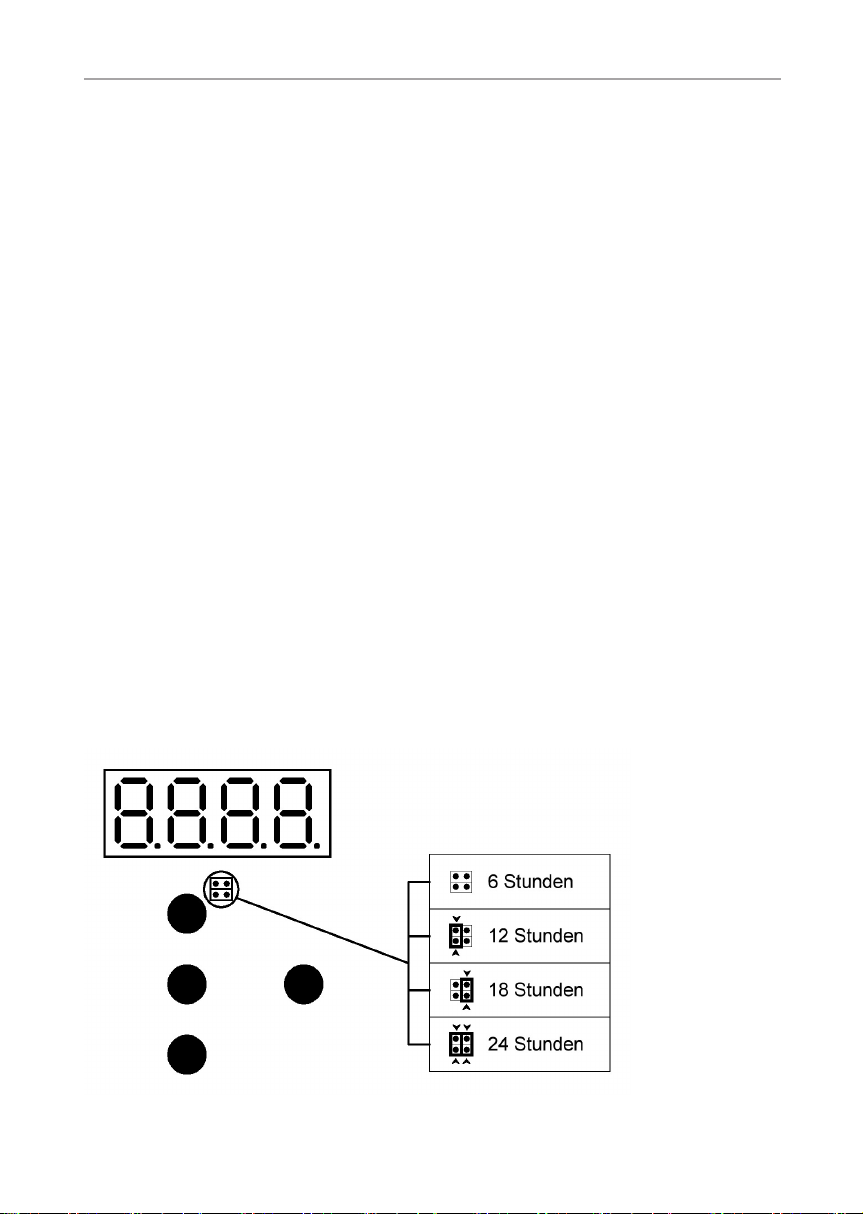
Über die 2 x 2 polige Stiftleiste auf der oberen Bedien-Platine kann die maximale
Heizdauer auf 12 h, 18 h oder 24 h eingestellt werden. Die dafür erforderlichen
Jumper können bei uns bestellt werden (O-JUMP).
Montageanweisung – nur für Fachpersonal S. 19/44
7.2. Einstellungen im Optionsmenü
Um in das Optionsmenü zu gelangen, drücken Sie gleichzeitig die Tasten UP/
DOWN 8 und START/STOP 7 und halten diese gedrückt, während Sie
die Steuerung mit dem EIN/AUS-Schalter 1 einschalten.
► In der Anzeige 6 erscheint: _ 0 _ _
Das Optionsmenü verfügt über 3 Menüpunkte, wobei jeder Menüpunkt weitere
Menüunterpunkte hat. Die erste angezeigte Zahl bestimmt den ersten Menüpunkt.
Mit den UP/DOWN Tasten 8 kann der gewünschte Menüpunkt ausgewählt
werden. Zum Bestätigen drücken Sie die Taste START/STOP 7
► In der Anzeige 6 erscheint eine neue Null: _ 0 0 _
Sie benden sich nun im Untermenü. Hier kann die Option ausgewählt werden
welche verändert werden soll. Um einen Schritt zurück zu gehen, muss solange
die Taste „UP“ oder „DOWN“ gedrückt werden, bis ein waagrechter Strich in der
Anzeige 6 erscheint. Zum Bestätigen die Taste „START/STOP 7 drücken.
Übersicht der einzelnen Menüpunkte:
(Die Zahl in Klammer zeigt die Einstellung im Auslieferzustand)
Menüpunkt 0 - Abgleich
Untermenü: 0 - Temperaturabgleich F2 (Ist-Wert) +/-15°C bei 90°C (5)
Menüpunkt 1 - Regelparameter
Untermenü: 0 - P-Anteil des Reglers von 0-255 (17)
Untermenü: 1 - I-Anteil des Reglers von 0-255 (48)
Untermenü: 3 - Relaisansteuerung: rollierend =0, synchron =1 (0)
DE
Gebrauchsanweisung für den Anwender S. 20/44
Menüpunkt 2 - Optionen (Melderelais REL/REL)
Untermenü: 0 - 0 = Melderelais deaktiviert (0)
1 = Sammelstörung (ErrX)
2 = Klimabetrieb (Relais „Ein“)
3 = Klimabetrieb + Trocknung (Relais „Ein“)
4 = Trocknung (Relais „Ein“)
5 = Saunabetrieb (Relais „Ein“)
6 = Soll-Temperatur erreicht (Relais „Ein“)
8 = Sammelstörung (ErrX oder „Fill“)
Um eine Einstellung zu ändern, drücken Sie die PROG/OK Taste 9. In der
Anzeige blinkt nun der zuletzt eingestellte Wert. Wählen Sie mit der Taste „UP“
oder „DOWN“ den gewünschten Wert aus. Zum Bestätigen der Auswahl drücken
Sie die PROG/OK Taste 9. Danach die Steuerung mit dem EIN/AUS-Schalter
1 ausschalten.
8. Bedienung
Beachten Sie die Abb.8 im Kapitel Abbildungen.
8.1. Licht einschalten
Das Licht in der Saunakabine kann unabhängig vom EIN/AUS-Schalter 1
eingeschaltet und ausgeschaltet werden.
Um das Licht einzuschalten bzw. auszuschalten, drücken Sie den Lichtschalter 2.
8.2. Saunasteuerung einschalten
WARNUNG!
Brandgefahr
Brennbare Gegenstände, die auf dem heißen Saunaofen liegen, können
sich entzünden und Brände verursachen.
● Legen Sie NIEMALS brennbare Gegenstände auf den Saunaofen.
● Stellen Sie sicher, dass KEINE brennbaren Gegenstände auf dem
Saunaofen liegen, bevor Sie die Saunasteuerung einschalten.

Gebrauchsanweisung für den Anwender S. 21/44
Drücken Sie den EIN/AUS-Schalter 1, um die Saunasteuerung ein zuschalten.
► Die Leuchtanzeigen c - f leuchten ca. 5 Sekunden auf.
► Die Leuchtanzeige TIME (Uhrzeit) g leuchtet.
► In der Anzeige 6 erscheint die Uhrzeit.
► Die Leuchtanzeige der zuletzt ausgewählten Badeform SAUNA h bzw.
CLIMA a leuchtet.
8.3. Einstellmöglichkeiten
1. Heizbeginn = Leuchtanzeige START f:
zum Einstellen des automatischen Heizbeginnes
von 0 - 24 Uhr, z.B. [18:00] Uhr
2. Heizdauer = Leuchtanzeige TIME e:
zum Einstellen der Heizdauer,
z.B. [02:30] Stunden und Minuten
3. Temperatur = Leuchtanzeige TEMP d:
die Temperatur von
10 - 110 °C im Sauna-Betrieb
und
10 - 80 °C im Clima-Betrieb
z.B. Sauna-Betrieb [95 °C]
4. Lüfterdrehzahl = Leuchtanzeige VENT c:
die Lüfterdrehzahl von 0 - 100 %, z.B. [50 % Prozent]
DE
Gebrauchsanweisung für den Anwender S. 22/44
5. Relative Feuchte = Leuchtanzeige CLIMA b:
die relative Feuchte von 10 - 80 % z. B. [70 %]
Die Einstellungen können während des Sauna- und Climabetriebes verändert
werden. Der Sauna Betrieb wird nach Ablauf einer eingegebenen Heizdauer
automatisch beendet. Im Clima-Betrieb erfolgt am Ende der Heizdauer ein
Nachtrocknungsprogramm (DRY).
Hinweis: Was ist der Sollwert oder Istwert?:
Sollwert = ist der Wert den man einstellt also vorgibt und haben möchte.
z.B. 90 °C
Istwert = ist der Wert der im Augenblick in der Kabine vorhanden ist.
z.B. 85 °C.
8.4. Menüpunkte anwählen
Durch Betätigung der Taster Up/Down 8 bewegt man sich auf- oder abwärts
durch die verschiedenen Menüpunkte.
Hat man eine Menüfunktion ausgewählt, betätigt man die PROG Taste 9. Nun
beginnt die Anzeige 6 zu blinken. In dem blinkendem Zustand kann man mit
den Tasten UP/DOWN 8 eine Einstellung des Wertes nach oben oder unten
vornehmen. Hat man den gewünschten Wert eingestellt, betätigt man wieder die
PROG/OK Taste 9. Der Wert wird übernommen und das Blinken der Anzeige
6 wird beendet. Längeres Betätigen der Taster UP/DOWN 8 ruft im blinken-
dem Zustand der Anzeige eine Schnellverstellung hervor.
Mit der START/STOP Taste 7 ist es möglich den Direktbetrieb zu starten oder
anschließend zu beenden.
Hinweis - Schnell-Lauf der Eingabewerte!
Dauerhaftes drücken der UP/DOWN Tasten 8 löst nach ca. 5 Sekunden
einen Schnell-Lauf der Eingabewerte aus.

Gebrauchsanweisung für den Anwender S. 23/44
8.5. Uhrzeit eingeben
Das Saunasteuergerät wird durch den Betriebsschalter 1 komplett vom Stromnetz getrennt. Die gespeicherten Einstellungen und die Uhrzeit wird durch eine
interne Batterie aufrechterhalten. Nach der Erstinbetriebnahme der Saunasteuerung muss die aktuelle Uhrzeit eingestellt werden.
1. Sauna-Steuerung einschalten
EIN /AUS Schalter 1 drücken:
● Die Leuchtanzeigen c - f leuchten ca. 5 Sekunden auf.
● Die Leuchtanzeige TIME (Uhrzeit) g leuchtet. (z.B. 12:00 Uhr): 12:00
● Die Leuchtanzeige der zuletzt ausgewählten Badeform SAUNA h bzw.
CLIMA a leuchtet.
2. Aktuelle Uhrzeit einstellen [0 - 24 Uhr]
Menüfunktion TIME muss aktiviert sein: Die Leuchtanzeige e leuchtet.
a) Taste PROG/OK 9 drücken:
● In der Anzeige 6 blinkt: 12:00 oder die bisher eingestellte Uhrzeit.
● Die Anzeige 6 blinkt 20 Sekunden, innerhalb dieser Zeit muss mit der
Einstellung begonnen werden, sonst endet der Einstellmodus, und er muss
erneut angewählt werden.
b) Mit den UP/DOWN Tasten 8 den gewünschten Wert eingeben, z.B. [18:00].
c) Taste PROG / OK 9 drücken:
Die Anzeige 6 hört auf zu blinken. Die Uhrzeit ist eingestellt.
DE

Gebrauchsanweisung für den Anwender S. 24/44
8.6. Sauna - Betrieb: Manueller Betrieb - Schnell-Start
1. Sauna-Steuerung einschalten
EIN/AUS Schalter 1 drücken.
Die Leuchtanzeigen c - f leuchten ca. 5 Sekundenauf.
● Die Leuchtanzeige der zuletzt ausgewählten
Badeform SAUNA h bzw. CLIMA a leuchtet.
● In der Anzeige 6 erscheint die aktuelle Uhrzeit, (z.B.16:30 Uhr): 16:30
2. Einstellen auf Sauna-Betrieb
Saunataster h betätigen.
● Die Leuchtanzeige des Saunatasters h leuchtet.
● In der Anzeige 6 wird die aktuelle Uhrzeit angezeigt.
3. Heizdauer eingeben (00:00 - 6:00)
● UP/DOWN Tasten 8 drücken bis die Leuchtanzeige TIME e leuchtet:
In der Anzeige 6 erscheint (im Stand-by): STOP
oder die Restheizzeit während des Betriebes.
● Taste PROG/OK 9 drücken:
In der Anzeige 6 blinkt: 06:00
oder der zuletzt eingestellte Wert.
● Mit den UP/DOWN Tasten 8 den gewünschten Wert eingeben, z. B. [02:30]:
In der Anzeige 6 blinkt: 02:30
● Taste PROG/OK 9 drücken:
In der Anzeige 6 erscheint (im Stand-by): STOP
oder den neu eingestellten Wert während des Heizbetriebes.
Die Heizdauer ist eingestellt.

Gebrauchsanweisung für den Anwender S. 25/44
4. Sauna-Steuerung starten
● Taste STAR /STOP 7 drücken:
In der Anzeige 6 erscheint die verbleibende
Heizzeit, z.B.: 02:30
Die Heizung beginnt zu heizen.
Die Leuchtanzeige 4 leuchtet.
5. Einstellungen ansehen / ändern
Während des Sauna- Betriebes können Sie sämtliche Temperatur-, Heizdauer-,
oder Lüfter-Einstellungen ansehen und ändern.
Soll-Werte verändern
1. Taste PROG/OK 9 drücken: In der Anzeige 6 blinkt der jeweilige
aktuelle Einstellwert.
2. Mit den UP/DOWN Tasten 8 den gewünschten Wert eingeben.
3. Taste PROG/OK 9 drücken: Der neue Einstellwert ist eingestellt.
6. Sauna-Steuerung ausschalten
a) Manuell
Taste START/STOP 7 drücken: Die Sauna-Heizung schaltet ab.
Die Leuchtanzeige HEIZEN 4 erlischt.
Die Steuerung ist im Stand-by.
DE
b) Selbsttätig
Nach Ablauf der eingestellten Heizzeit (siehe Kapitel „Heizdauer eingeben
(00:00 - 06:00)“) schaltet die Sauna-Steuerung die Heizung automatisch ab.
– Es ertönt 10 Sekunden ein Dauerton.
– Die Leuchtanzeige HEIZEN 4 erlischt.
– Die Steuerung ist im Stand-by-Betrieb.
Gebrauchsanweisung für den Anwender S. 26/44
8.7. Sauna - Betrieb: Automatik-Betrieb
1. Sauna-Steuerung einschalten
● EIN/AUS Schalter 1 drücken.
Die Leuchtanzeigen leuchten c - f ca. 5 Sekunden auf.
Die Leuchtanzeige der zuletzt ausgewählten
Badeform SAUNA h bzw. CLIMA a leuchtet.
In der Anzeige 6 erscheint die aktuelle Uhrzeit,(z.B.16:30 Uhr): 16:30
2. Einstellen auf Sauna-Betrieb
● Saunataster h betätigen.
Die Leuchtanzeige des Saunatasters h leuchtet.
In der Anzeige 6 wird die aktuelle Uhrzeit angezeigt.
Die Leuchtanzeige AUTOMATIC 5 leuchtet nicht.
3. Heizbeginn wählen [00:00 - 23:59 Uhr]
WARNUNG
Brandgefahr
Brennbare Gegenstände, die auf dem heißen Saunaofen liegen, können
sich entzünden und Brände verursachen.
● Legen Sie NIEMALS brennbare Gegenstände auf den Saunaofen.
● Stellen Sie sicher, dass KEINE brennbaren Gegenstände auf dem
Saunaofen liegen, bevor Sie den Automatik-Betrieb aktivieren.
● UP/DOWN Tasten 8 drücken bis die Leuchtanzeige
START leuchtet:
● In der Anzeige 6 erscheint: OFF
oder der zuletzt eingestellte Wert.

Gebrauchsanweisung für den Anwender S. 27/44
● Taste PROG/OK 9 drücken:
In der Anzeige 6 blinkt: OFF
oder der zuletzt eingestellte Wert.
Mit den UP/DOWN Tasten 8 den gewünschten
Wert eingeben, z. B. [18:00]:
In der Anzeige 6 blinkt: 18:00
Taste PROG/OK 9 drücken:
In der Anzeige 6 erscheint: 18:00
Die Leuchtanzeige AUTOMATIC 5 leuchtet.
Der automatische Heizbeginn ist eingestellt.
Hinweis - Heizbeginn deaktivieren:
Zum Ausschalten des automatischen Heizbeginnes Schalter EIN/AUS
1 aus und wieder einschalten. Die Leuchtanzeige AUTOMATIC 5
schaltet aus, oder nochmaliges Betätigen der Betriebsart SAUNA h
oder CLIMA a. Die Leuchtanzeige AUTOMATIC 5 schaltet aus.
4. Heizdauer eingeben (00:00 - 06:00)
● UP/DOWN Tasten 8 drücken bis die Leuchtanzeige TIME e leuchtet:
DE
In der Anzeige 6 erscheint (im Stand-by): STOP
oder die restliche Betriebszeit während des Heizbetriebes.
● Taste PROG/OK 9 drücken:
In der Anzeige 6 blinkt: 06:00
oder der zuletzt eingestellte Wert.
● Mit den UP/DOWN Tasten 8 den gewünschten
Wert eingeben, z. B. [02:30]:
In der Anzeige 6 blinkt: 02:30

Gebrauchsanweisung für den Anwender S. 28/44
● 4. Taste PROG/OK 9 drücken:
In der Anzeige 6 erscheint (im Stand-by): STOP
oder die neu eingegebene Heizdauer während des Heizbetriebes.
Die Heizdauer ist eingestellt.
5. 7.5 Temperatur eingeben (10 - 110°C)
● UP/DOWN Tasten 8 drücken bis die Leuchtanzeige TEMP d leuchtet:
In der Anzeige 6 erscheint die aktuelle Sauna-Innenraumtemperatur,
z.B. [22° C]: 22°
● Taste PROG/ OK 9 drücken:
In der Anzeige 6 blinkt die zuletzt eingestellteTemperatur, z.B. [90° C]:
90°
● Mit den UP/DOWN Tasten 8 den neuen gewünschten Wert eingeben, z.
B. [95°C]:
In der Anzeige 6 blinkt: 95°
● Taste PROG/OK 9 drücken:
In der Anzeige 6 erscheint wieder die aktuelle Sauna-Innenraumtemperatur,
z.B. [22° C]: 22°
Die Temperatur ist eingestellt.
6. Lüfter einstellen [0 - 100 % = P]
0 = aus / 100 = max.
● UP/DOWN Tasten 8 drücken bis die Leuchtanzeige VENT c leuchtet:
In der Anzeige 6 erscheint: 60 P
oder der zuletzt eingestellte Wert.

Gebrauchsanweisung für den Anwender S. 29/44
● Taste PROG/OK 9 drücken:
In der Anzeige 6 blinkt: 60 P
oder der zuletzt eingestellte Wert.
● Mit den UP/DOWN Tasten 8 den gewünschten Wert eingeben, z. B. [50 %]:
In der Anzeige 6 blinkt: 50 P
● Taste PROG/OK 9 drücken:
In der Anzeige 6 erscheint die eingestellte Lüfterleistung: 50 P
Die Lüfterdrehzahl ist eingestellt.
7. Einstellungen ansehen / ändern
Während des Sauna- Betriebes können Sie sämtliche Temperatur-, Heizdauer-,
oder Lüfter-Einstellungen ansehen und ändern.
a) Soll-Werte verändern / anzeigen
● Taste PROG/OK 9 drücken: In der Anzeige 6 blinkt der jeweilige aktuelle
Einstellwert.
● Mit den UP/DOWN Tasten 8 den gewünschten Wert eingeben / oder ein-
gestellten Wert anzeigen
● Taste PROG/OK 9 drücken: Der neue Einstellwert ist eingestellt.
b) Manuelles Abschalten des Programmes
● Während des Heizens:
Taste START/STOP 7 drücken:
– Die Sauna-Heizung schaltet ab.
– Die Leuchtanzeige HEIZEN 4 erlischt.
– Die Steuerung bendet sich im Stand-by- Betrieb.
DE

Gebrauchsanweisung für den Anwender S. 30/44
c) Selbsttätiges Abschalten
● Nach Ablauf der eingestellten Heizzeit schaltet die Sauna-Steuerung die
Heizung automatisch ab.
– Es ertönt 10 Sekunden ein Dauerton.
– Die Leuchtanzeige HEIZEN 4 erlischt.
– Die Steuerung bendet sich im Stand-by-Betrieb.
8. Nach dem Automatik-Betrieb
Der automatische Heizbetrieb (siehe Kapitel „Einstellen auf Sauna-Betrieb“)
wird aus Sicherheitsgründen immer nur einmal aktiviert. Möchten Sie die SaunaSteuerung mit den selben Einstellungen wieder aktivieren:
● UP/DOWN Tasten 8 drücken bis Leuchtanzeige
Start f leuchtet.
Die Anzeige 6 zeigt: OFF
oder die zuletzt eingestellte Startzeit.
● Taste PROG/OK 9 einmal drücken.
In der Anzeige 6 blinkt die automatische Startzeit.
● Taste PROG/OK 9 einmal drücken.
Die Anzeige 6 hört auf zu blinken.
Die Leuchtanzeige AUTOMATIC 5 leuchtet.
Die vorgewählte Betriebart SAUNA h oder CLIMA a ist aktiviert.
Möchten Sie die Sauna-Steuerung mit geänderten Einstellungen neu aktivieren:
siehe Kapitel 8.7. Sauna - Betrieb: Automatik-Betrieb

Gebrauchsanweisung für den Anwender S. 31/44
9. Automatik-Betrieb aktivieren
Es besteht eine weitere Möglichkeit zu Kapitel „Nach dem Automatik-Betrieb“
den Automatic-Betrieb mit den eingestellten Werten zu aktivieren.
● Taster SAUNA h für den Sauna-Betrieb oder
Taster CLIMA a für den Clima-Betrieb drücken und 3 Sekunden halten.
Die Leuchtanzeige AUTOMATIC 5 leuchtet.
8.8. Clima Betrieb: Manueller Betrieb - Schnell-Start
1. Sauna-Steuerung einschalten
● EIN /AUS Schalter 1 drücken.
Die Leuchtanzeigen c - f leuchten ca. 5 Sekunden auf.
Die Leuchtanzeige der zuletzt ausgewählten Badeform SAUNA h bzw.
CLIMA a leuchtet.
In der Anzeige 6 erscheint die aktuelle Uhrzeit, (z.B. 16:30 Uhr): 16:30
2. Einstellen auf Clima-Betrieb
● Climataste a betätigen.
Die Leuchtanzeige des Climatasters a leuchtet und die Leuchtanzeige des
Saunatasters h schaltet aus.
Die Leuchtanzeigen leuchten c - f ca. 5 Sekunden auf.
Danach erscheint in der Anzeige 6 die aktuelle Uhrzeit.
● Taste START / STOP 7 drücken.
Die Heizung wird nun sofort mit dem vorprogrammierten Temperaturwert
von 50 °C oder mit der zuletzt eingestellten Temperatur in Gang gesetzt, der
Heizvorgang beginnt sofort.
DE

Gebrauchsanweisung für den Anwender S. 32/44
3. Heizdauer eingeben (00:00 - 6:00)
● UP/DOWN Tasten 8 drücken bis die Leuchtanzeige TIME e leuchtet:
In der Anzeige 6 erscheint: STOP
wenn die Steuerung noch nicht gestartet wurde.
● Taste PROG/ OK 9 drücken:
In der Anzeige 6 blinkt: 06.00
oder der zuletzt eingestellte Wert.
● Mit den UP/DOWN Tasten 8 den gewünschten
Wert eingeben, z. B. [02:30]:
In der Anzeige 6 blinkt: 02:30
● Taste PROG/ OK 9 drücken:
In der Anzeige 6 erscheint: STOP im Stand-by oder 02:30
wenn die Heizdauer während des Heizbetriebes geändert wurde. Die Heiz-
dauer ist eingestellt.

Gebrauchsanweisung für den Anwender S. 33/44
8.9. Clima Betrieb: Automatic
1. Sauna-Steuerung einschalten
● EIN /AUS Taste 1 drücken.
Die Leuchtanzeigen b - f leuchten ca. 5 Sekunden auf.
Die Leuchtanzeige der zuletzt ausgewählten Badeform SAUNA h bzw.
CLIMA a leuchtet.
In der Anzeige 6 erscheint die aktuelle Uhrzeit, (z.B. 16:30 Uhr): 16:30
2. Einstellen auf Clima-Betrieb
● Climataste a betätigen.
Die Leuchtanzeige des Climatasters a leuchtet.
In der Anzeige 6 erscheint die aktuelle Uhrzeit.
3. Heizbeginn wählen [00:00 - 23:59 Uhr]
WARNUNG
Brandgefahr
Brennbare Gegenstände, die auf dem heißen Saunaofen liegen, können
sich entzünden und Brände verursachen.
● Legen Sie NIEMALS brennbare Gegenstände auf den Saunaofen.
● Stellen Sie sicher, dass KEINE brennbaren Gegenstände auf dem
Saunaofen liegen, bevor Sie den Automatik-Betrieb aktivieren.
● UP/DOWN Tasten 8 drücken bis die Leuchtanzeige START f leuchtet:
In der Anzeige 6 erscheint: OFF
oder der zuletzt eingestellte Wert.
● Taste PROG/OK 9 drücken:
In der Anzeige 6 blinkt: OFF
oder der zuletzt eingestellte Wert.
DE

Gebrauchsanweisung für den Anwender S. 34/44
● Mit den UP/DOWN Tasten 8 den gewünschten
Wert eingeben, z.B. [18:00]:
In der Anzeige 6 blinkt: 18:00
● Taste PROG/OK 9 drücken:
In der Anzeige 6 erscheint: 18:00
Die Leuchtanzeige AUTOMATIC 5 leuchtet.
Der automatische Heizbeginn ist eingestellt.
Hinweis - Heizbeginn deaktivieren:
Zum Ausschalten des automatischen Heizbeginnes Schalter EIN/AUS
1 aus und wieder einschalten. Die Leuchtanzeige AUTOMATIC 5
schaltet aus, oder nochmaliges Betätigen der Betriebsart SAUNA h
oder CLIMA a. Die Leuchtanzeige AUTOMATIC 5 schaltet aus.
4. Temperatur eingeben (10 - 80 °C)
UP/DOWN Tasten 8 drücken bis die Leuchtanzeige TEMP d leuchtet:
In der Anzeige 6 erscheint die aktuelle Sauna-Innenraumtemperatur,
z.B. [22 °C]: 22° oder der zuletzt eingestellte Wert.
● Taste PROG/ OK 9 drücken:
In der Anzeige 6 blinkt: 50° oder der zuletzt eingestellte Wert.
● Mit den UP/DOWN Tasten 8 den gewünschten
Wert eingeben, (min. 10 °C - max. 80 °C) z. B. [65 °C]:
In der Anzeige 6 blinkt: 65°
● Taste PROG/ OK 9 drücken:
In der Anzeige 6 erscheint wieder die aktuelle Sauna-Innentemperatur,
z.B. [22 °C]: 22°
Die Temperatur ist eingestellt.

Gebrauchsanweisung für den Anwender S. 35/44
5. Lüfter einstellen [0 - 100 % = P] 0 = aus / 100 = max.
● UP/DOWN Tasten 8 drücken bis die Leuchtanzeige VENT c leuchtet:
In der Anzeige 6 erscheint: 60 P
oder der zuletzt eingestellte Wert.
● Taste PROG/ OK 9 drücken:
In der Anzeige 6 blinkt: 60 P
oder der zuletzt eingestellte Wert.
● Mit den UP/DOWN Tasten 8 den gewünschten Wert eingeben, z. B. [50 %]:
In der Anzeige 6 blinkt: 50 P
● Taste PROG/ OK 9 drücken:
In der Anzeige 6 erscheint der eingestellte Lüfterwert: 50 P
Die Veränderung der Lüfterdrehzahl ist eingestellt.
Hinweis - wenn kein Lüfter installiert ist:
wählen Sie die Einstellung 0 P = OFF = AUS.
6. Relative Feuchte einstellen
● 1. UP/DOWN Tasten 8 drücken bis die Leuchtanzeige CLIMA b leuchtet:
In der Anzeige 6 erscheint die aktuelle Luftfeuchte in der Kabine z.B. [15 H]:
15 H
● Taste PROG/OK 9 drücken:
In der Anzeige 6 blinkt: 50 H
oder der zuletzt eingestellte Wert.
DE

Gebrauchsanweisung für den Anwender S. 36/44
● Mit den UP/DOWN Tasten 8 den gewünschten
Wert eingeben, (min. 10 % - max. 80 %) z. B. [50 %]:
In der Anzeige 6 blinkt: 50 H
● Taste PROG/ OK 9 drücken:
In der Anzeige 6 erscheint die charakteristische Luftfeuchte in der Kabine,
z.B. [15 H] : 15 H
Der neue Sollwert für die relative Luftfeuchtigkeit ist eingestellt.
Hinweis - Signalton
Ertönt nach der Temperatureingabe ein Signalton und die Leuchtanzeige
TEMP d leuchtet, beachten Sie bitte folgendes: Die Funktionen Temperatur d und die relative Luftfeuchtigkeit b sind direkt voneinander
abhängig. Um Sicherheitsbestimmungen einzuhalten warnt das Gerät
per Signalton und wählt automatisch den maximal möglichen Wert der
von einander abhängigen Funktionen.
8.10. Wasserstandskontrolle
1. Die Steuerung verfügt für den Clima- Betrieb über die Möglichkeit einer auto-
matischen Wasserstandsüberwachung. Ist im Verdampfer zu wenig Wasser
(ca. 1L), wird dies durch einen wiederkehrenden Warnton und demText
FILL in der Anzeige 6 signalisiert. Gleichzeitig schaltet der Verdampfer
selbstständig ab.
► Füllen Sie Wasser auf.
► Die Meldung FILL erlischt nach kurzer Zeit.
Hinweis
Dies setzt jedoch voraus, dass der Verdampfer den hierfür erforderlichen
Signalausgang besitzt. Der Betrieb ohne diese Funktion ist ebenso möglich.

Gebrauchsanweisung für den Anwender S. 37/44
8.11. Automatisches Kabinen-Nachtrocknungs-Programm
Das Kabinen-Nachtrocknungs-Programm startet automatisch nach Beendigung
des Clima-Betriebes und trocknet die Kabine:
Hinweis
Es wird empfohlen, bezüglich der Nachtrocknung entsprechende Bedienungshinweise des Kabinenherstellers zu beachten. Grundsätzlich sollte
das Nachtrocknungsprogramm nicht vorzeitig abgebrochen werden, da
es sonst zu Schäden an der Kabine kommen kann (z.B. Schimmel- und
Fäulnisbildung).
Nach Beendigung des Clima-Betriebes wird das Nachtrocknungsprogramm automatisch gestartet. Die Nachtrocknungsphase kann bis zu 85 Minuten dauern,
die Kabinentemperatur wird geregelt, und der Lüfter läuft mit unterschiedlichen
Drehzahlen. Nach Beendigung des Trockenprogammes schaltet die Anzeige
6 auf Stand-By.
8.12. Bei längeren Betriebspausen
EIN/AUS Schalter 1 der Steuerung ausschalten.
8.13. Voreinstellungen
DE
Sie erhalten Ihre Steuerung mit einer vom Werk programmierten Voreinstellung.
Die jeweiligen Werte der Funktionen entnehmen Sie folgender Tabelle:
Saunabetrieb:
Heizbeginn OFF keine Einstellung
Heizdauer 6 Stunden
Temperatur 90 °C
Ventilator 60 P
Climabetrieb:
Heizbeginn OFF keine Einstellung
Heizdauer 6 Stunden
Temperatur 50 °C
Ventilator 60 P
Clima 50 H

Gebrauchsanweisung für den Anwender S. 38/44
9. Problemlösung
9.1. Innenraumbeleuchtung leuchtet nicht
● Schalter 2 ausschalten.
● Hauptsicherungen der Steuerung im Sicherungskasten ausschalten.
● Glühlampe austauschen.
● Hauptsicherungen einschalten und Schalter 2 betätigen.
9.2. Batterie für Uhr wechseln
Beachten Sie die Abb.3 im Kapitel Abbildungen.
WARNUNG!
Stromschlag
Vor dem Öffnen der Gehäuseabdeckung Sauna-Steuerung allpolig vom
Netz trennen und gegen Wiedereinschalten sichern.
1. Gehäuseabdeckung 5 gemäß 4.1. Saunasteuerung montieren auf Sei-
te 11 abnehmen.
2. Bedienteil 1 vorsichtig vom Gehäuseunterteil 6 abziehen.
3. Batterie (Typ CR2032) 8 für Uhr auf obere Platine austauschen (Abb. 3).
4. Laschen 2 des Bedienteiles 1 in die beiden seitlichen Aufnahmen 3
einsetzen und vorsichtig bis zum Anschlag auf das Gehäuseunterteil 6
drücken.
5. Gehäuseabdeckung auf das Gehäuseunterteil 1 aufsetzen, nach unten
schwenken und bis zum hörbaren Einrasten drücken. Sicheren Sitz der
Steuerung prüfen.
9.3. Sicherungen wechseln
Beachten Sie die Abb.3 im Kapitel Abbildungen.
WARNUNG!
Stromschlag
Vor dem Öffnen der Gehäuseabdeckung Sauna-Steuerung allpolig vom
Netz trennen und gegen Wiedereinschalten sichern.
1. Gehäuseabdeckung 5 gemäß 4.1. Saunasteuerung montieren (Abb.1)
auf Seite 11 abnehmen.
2. Bedienteil 1 vorsichtig vom Gehäuseunterteil 6 abziehen.

Gebrauchsanweisung für den Anwender S. 39/44
3. Sicherung für Innenraumbeleuchtung (Feinsicherung 5 x 20 T2,0 A/ 250 V)
9 oder Sicherung für Lüfter (Kleinstsicherung TR 5 - T 1,0 A/ 250V) 7 oder
Sicherung für die Elektronik des Gerätes (Feinsicherung 5 x2 0 T630 mA/
250 V) A austauschen (Abb. 3).
4. Laschen 2 des Bedienteiles 1 in die beiden seitlichen Aufnahmen 3
einsetzen und vorsichtig bis zum Anschlag auf das Gehäuseunterteil 6
drücken.
5. Gehäuseabdeckung 5 auf das Gehäuseunterteil 6 aufsetzen, nach
unten schwenken und bis zum hörbaren Einrasten drücken. Sicheren Sitz
der Steuerung prüfen.
9.4. Fehlermeldungen
Eine Fehlermeldung signalisiert einen elektrischen Defekt der Anlage. Die Saunasteuerung ist nicht mehr betriebsbereit.
Fehler Beschreibung Ursache / Behebung
ERR 1 Übertemperatursicherung
F1 defekt
ERR 3 Fühlerleitungsbruch F1 Siehe Punkt 6. Prüfungen durchführen
ERR 4 Leitungskurzschluss F1 Überprüfen Sie die Fühlerleitungen und
ERR 5 Leitungskurzschluss
FTS2 / F2 (TemperaturFühler)
ERR 6 Leitungsunterbrechnung
FTS2 / F2 (TemperaturFühler)
ERR 7 Leitungsunterbrechung
FTS2 (Feuchte-Sensorik)
oder F2 wird nicht erkannt
ERR 8 Leitungskurzschluss
FTS2 (Feuchte-Sensorik)
Siehe Punkt 6. Prüfungen durchführen
auf Seite 17
auf Seite 17
die Anschlussklemmen
Überprüfen Sie die Fühlerleitungen und
die Anschlussklemmen
Überprüfen Sie die Fühlerleitungen und
die Anschlussklemmen
Überprüfen Sie die Fühlerleitungen
und die Anschlussklemmen;
Steuerung neu einschalten, 30 sec.
PROG/OK -Taste drücken
Überprüfen Sie die Fühlerleitungen und
die Anschlussklemmen
DE

Gebrauchsanweisung für den Anwender S. 40/44
9.5. Meldungen in der Anzeige
1. LL in der Anzeige
In der Anzeige 6 erscheint: LL
Innenraum-Temperatur ist unterhalb 10 °C.
2. HH in der Anzeige
In der Anzeige 6 erscheint: HH
Die Innenraum-Temperatur ist oberhalb 115 °C.
● Bei einmaligen Erscheinen der Meldung kann die Sauna-Steuerung
gefahrlos weiter betrieben werden.
● Die Sauna-Steuerung regelt die Temperatur automatisch nach unten.
Bei wiederholten Erscheinen der Meldung HH ist die Sauna-Steuerung nicht
mehr betriebsbereit:
1. Hauptsicherungen der Sauna-Steuerung im Sicherungskasten ausschalten.
2. Verständigen Sie Ihren Kundendienst oder Elektroinstallateur.
3. Kennzeichnen Sie die Steuerung als defekt.
3. FILL in der Anzeige
In der Anzeige 6 erscheint: FILL
Wasserstandsüberwachung! Wasser auffüllen (siehe Kapitel 8.10.)
4. Maximale Heizdauer
Aus Sicherheitsgründen ist die maximale Heizdauer bei privaten Saunakabinen
auf 6 Stunden begrenzt. Die Heizung schaltet automatisch ab.

Gebrauchsanweisung für den Anwender S. 41/44
10. Reinigung
VORSICHT - SCHÄDEN AM GERÄT:
Die Steuerung sollte nicht mit Wasser übergossen oder sehr feucht
gereinigt werden. Benutzen Sie zum Reinigen ein leicht angefeuchtetes
Reinigungstuch, das mit etwas milder Seifenlauge (Spülmittel) versehen ist.
11. Wartung
● Die Steuerung ist wartungsfrei.
● Im gewerblichen Einsatz ist die Steuerung gemäß den aktuellen Unfall-
Verhütungs-Vorschriften zu Warten / Prüfen.
12. Entsorgung
● Entsorgen Sie die Verpackungsmaterialien nach den gültigen
Entsorgungsrichtlinien.
● Altgeräte enthalten wiederverwendbare Materialien, aber auch
schädliche Stoffe. Geben Sie Ihr Altgerät deshalb auf keinen Fall
in den Restmüll, sondern entsorgen Sie das Gerät nach den örtlich
geltenden Vorschriften.
DE

Montageanweisung – nur für Fachpersonal S. 42/44
13. Technische Daten
Umgebungsbedingungen:
Lagertemperatur: -25 °C bis + 70 °C
Umgebungstemperatur: -10 °C bis + 40 °C
Luftfeuchtigkeit: max. 95 %
Steuerung:
Abmessungen: 245 x 220 x 85 mm
Schaltspannung / dreiphasig 3N: 400 V
Frequenz: 50 / 60 Hz
Schaltleistung / Heizung: 3 x 3,5 kW
Schaltstrom pro Phase / Heizung: 16 A
Schaltleistung / Verdampfer: 3,5 kW
Schaltstrom / Verdampfer: 16 A
Nennspannung: 230 V
Schutzart (Spritzwassergeschützt): IPX 4
Anschluss an das Versorgungsnetz als Festverdrahtung (Festanschluss).
Licht:
Schaltstrom: 2 A
Lüfter:
Schaltstrom: 230 V, 1 A
Thermische Sicherheit:
● Ofen-Fühler mit Übertemperatur-Sicherung. (Abschalt-Temperatur 139 °C)
● Automatische Heizzeitbegrenzung nach max. 6 Stunden (bei privaten Anlagen).
● Zweifühlersystem mit Temperaturregelung über der Bank.

Montageanweisung – nur für Fachpersonal S. 43/44
Einstellbereiche:
Sauna-Betrieb: 10 - 110 °C am Bankfühler FII/FTS2
Clima-Betrieb: 10 - 80 °C an der Bank
Verdampfer: 10 - 80 % relative Luftfeuchte
Lüfter: 00 - 100 % Lüfterleistung
Vorwahlzeit: in 1 Minuten Stufen
Max. Vorwahlzeit: 23 Stunden 59 Minuten
max. einstellbare Heizdauer: 6 Stunden*
* Die EN 60335-2-53 schreibt für private Saunen eine Heizzeitbegrenzung von 6 h vor. Für
Saunen in Hotels, Wohnblöcken und ähnlichen Standorten ist eine Heizzeitbegrenzung
von 12 h zulässig. Die Erweiterung der Heizzeitbegrenzung auf 18 h oder 24 h ist nur in
öffentlichen Saunen gestattet.
Anschlussleitungen:
Versorgungsleitung: min. 5 x 2,5 mm²
Ofenzuleitung (temperaturbeständig bis 150 °C): min. 2,5 mm²
Fühlerleitungen (temperaturbeständig bis 150 °C): min. 0,5 mm²
Lichtleitung: min. 1,5 mm²
DE
Lüfterleitung: min. 1,5 mm²
Maximale Leitungslängen:
Ofenfühler F 1: 10 m
Bankfühler F 2 / FTS2: 10 m
Zusatz- Leistungsteile:
S2-18: Erhöhung der Schaltleistung von 10,5 kW auf
18 kW Gesamtleistung;
S2-30: Erhöhung der Schaltleistung
von 10,5 kW auf 30 kW Gesamtleistung.

Montageanweisung – nur für Fachpersonal S. 44/44

Sauna control unit
Saunasteuerung CK 3
Montageanweisung
Gebrauchsanweisung
CK 31
O-CK31
INSTRUCTIONS FOR INSTALLATION AND USE
English
AUTOMATIC
DRY
SAUNA
CLIMA
VENT
CLIMA
EN
Version 04/19 ID no. 1-021-752

Table of Contents
1. About this instruction manual 4
2. Important information for your safety 5
2.1. Intended use 5
2.2. Safety information for the installer 6
2.3. Safety information for the user 7
3. Product description 8
3.1. Scope of delivery 8
3.2. Optional accessories 8
3.3. Product functions 8
3.4. Sauna operating modes 9
3.5. Sensor operating modes 10
4. Installation 11
4.1. Installing the sauna control unit 11
4.2. Installing the heater sensor F1 with excess temperature fuse 12
4.3. Installing bench sensor F2 (optional) 13
4.4. Installing the humidity temperature sensor FTS2 (optional) 13
5. Electrical connection 14
5.1. Connecting the supply line, heater 14
5.2. Connecting the evaporator 15
5.3. Connecting the light 15
5.4. Connecting the fan (optional) 15
5.5. Connecting the optional power enhancement 15
5.6. Connecting heater sensor F1 15
5.7. Installing bench sensor F2 (optional) 16
5.8. Installing humidity temperature sensor FTS2 (optional) 16
5.9. Finishing the installation 16
6. Performing tests 17

Table of Contents
7. Starting up 18
7.1. Setting the heating period limit 18
7.2. Settings in the Options menu 19
8. Operation 20
8.1. Switching on the light 20
8.2. Switching on the sauna control unit 20
8.3. Setting options 21
8.4. Selecting menu items 22
8.5. Entering the time 23
8.6. Sauna mode: Manual operation - quick start 24
8.7. Sauna mode: Automatic mode 26
8.8. Climate mode: Manual operation - quick start 31
8.9. Climate mode: Automatic 33
8.10. Water level control 36
8.11. Automatic cabin night-drying program 37
8.12. For longer breaks in operation 37
8.13. Pre-settings 37
9. Troubleshooting 38
9.1. Interior lighting does not work 38
9.2. Changing the clock battery 38
9.3. Changing fuses 38
9.4. Error messages 39
9.5. Messages in the display 40
10. Cleaning 41
11. Maintenance 41
12. Disposal 41
13. Technical data 42

Instructions for installation and use p. 4/44
1. About this instruction manual
Read these instructions for installation and use carefully and keep them within
reach of the sauna control unit. This ensures that you can refer to information
regarding your safety and regarding operation at any time.
These installation and operating instructions can also be found in the
downloads section of our website: www.sentiotec.com/downloads.
Symbols used for warning notices
In these instructions for installation and use, a warning notice located next to
an activity indicates that this activity poses a risk. Always observe the warning
notices. This prevents damage to property and injuries which could, in the worst
case, be fatal.
The warning notices contain keywords, which have the following meanings:
DANGER!
Serious or fatal injury will occur if this warning notice is not observed.
WARNING!
Serious or fatal injury can occur if this warning notice is not observed.
CAUTION!
Minor injuries can occur if this warning notice is not observed.
ATTENTION!
This keyword is a warning that damage to property can occur.
Other symbols
This symbol indicates tips and useful information.

Instructions for installation and use p. 5/44
2. Important information for your safety
The CK 31 sauna control unit has been produced in accordance
with the applicable safety regulations for technical units. However,
hazards may occur during use. Therefore adhere to the following
safety information and the specic warning notices in the individual
chapters. Also observe the safety information for the devices connected.
2.1. Intended use
The CK 31 sauna control unit is used exclusively for operating and
controlling the sauna functions in accordance with the technical data.
The CK 31 sauna control units may only be used for operating
and controlling 3 heating circuits with a maximum heating capacity
of 3.5 kW per heating circuit. The maximum evaporator capacity
totals 3.5 kW.
Any use exceeding this scope is considered improper use. Improper
use can result in damage to the product, in severe injuries or death.
EN

Instructions for installation and use p. 6/44
2.2. Safety information for the installer
● Installation may only be performed by a qualied electrician or
similarly qualied person. Work on the sauna control unit may
only be performed when the power has been disconnected.
● An all-pole disconnecting device with full cut-off compliant with
overvoltage category III must be tted on-site.
● The sauna control unit must be installed outside the sauna room
at a height of approx. 1.70 m or in accordance with the recommendation issued by the sauna manufacturer. The ambient
temperature must be within a range spanning -10 °C to +40 °C.
● The heater sensor must be attached in a way that it is not af-
fected by a ow of air.
● The heater supply cable must have a minimum cross-section of
2.5 mm2 and be temperature resistant up to 150 °C.
● Also comply with the regulations applicable at the installation
location.
● For your own safety, consult your supplier in the event of prob-
lems that are not explained in sufcient detail in the installation
instructions.

Instructions for installation and use p. 7/44
2.3. Safety information for the user
● The sauna control unit must not be used by children under 8 years
old.
● The sauna control unit may be used by children above 8 years
old, by persons with limited psychological, sensory or mental
capabilities or by persons with lack of experience/knowledge
only when:
– They are supervised.
– Tthey have been shown how to use the device safely and
are aware of the hazards that could occur.
● Children must not play with the sauna control unit.
● Children under 14 years of age may only clean the sauna control
unit if they are supervised.
● For health reasons, do not use the sauna when under the inu-
ence of alcohol, medication or drugs.
● Make sure that no ammable objects have been placed on the
sauna heater before the sauna control unit is switched on.
● Make sure that no ammable objects have been placed on the
sauna heater before you activate the pre-set timer function.
● For your own safety, consult your supplier in the event of prob-
lems that are not described in sufcient detail in the operating
instructions.
EN

Instructions for installation and use p. 8/44
3. Product description
3.1. Scope of delivery
● Sauna control unit
● Heater sensor with integrated excess temperature fuse (F1)
● Sensor wires
● Installation material
3.2. Optional accessories
● Bench sensor (item number: O-F2)
● Humidity temperature sensor (item number: O-FTS2)
● Power booster (item number: O-S2-18 / O-S2-30)
● Safety shut-off (item number: HT-SWL)
NOTE – optional accessories:
The F2 sensor, or alternatively the FTS 2 humidity temperature sensor, must be ordered separately, otherwise the sauna control unit is not
operational.
3.3. Product functions
The CK 31 sauna control unit features the following functions:
● Regulation of combi sauna heaters with a heating output of up to 10.5 kW
and an evaporation output of up to 3.5 kW.
● A power booster allows the maximum contact rating to be increased from
10.5 kW to 18 kW or 30 kW.
● Intensity regulation of a fan (up to 100 W).
● Pre-set time function (up to 23 hours 59 minutes)
● Automatic heating period limiter
The sauna control unit shuts down automatically after the maximum heating
period for safety reasons. The maximum heating period can be set to 6 h,
12 h, 18 h or 24 h.

Instructions for installation and use p. 9/44
● Post-drying programme
Once climate mode has nished, the post-drying programme starts automatically to prevent mould or rot from forming in the sauna room. The post-drying
phase can last up to 85 minutes. The cabin temperature is regulated and the
fans run at different speeds.
● Excess temperature fuse
The excess temperature fuse is installed in the housing for the heater sensor. Should the sauna heater continue heating after reaching the preferred
temperature due to a defect, the excess temperature fuse switches off at
a temperature of approx. 139 °C above the sauna heater.
3.4. Sauna operating modes
The CK 31 sauna control unit provides two operating modes, sauna mode and
climate mode.
Sauna mode
Dry heat is provided in sauna mode. The temperature in the room is high (80 to
100 °C) The humidity level of maximum 10% is low. The indicator lights 4, 5
and c - g are red during sauna operation.
Climate mode
The evaporator operates along with the sauna heater in climate mode. The
temperature in the sauna room is lower (approx. 40 to 65 °C) than in sauna
mode, with the relative humidity being considerably higher, spanning 35% to
approximately 70%. The maximum humidity level which can be set depends
on the temperature of the sauna. The higher the sauna temperature, the lower
the maximum humidity level which can be set. The indicator lights 4, 5 and
b - g are green during climate mode.
EN

Instructions for installation and use p. 10/44
3.5. Sensor operating modes
The sauna control unit is operator by two sensors. A temperature sensor (bench
sensor, F2) or a humidity sensor (FTS2) can be used as the second sensor.
Mode with bench sensor (F2)
In two-sensor mode with bench sensor, a second temperature sensor (bench
sensor) is installed above the rear sauna bench. The sauna control unit displays
the temperature measured by the bench sensor as the actual temperature.
In two-sensor mode with bench sensor, the humidity is timed. Only the set
value for the humidity level (in % of relative humidity) is displayed by the sauna
control unit. The actual humidity level in the sauna room when humidity is timed
depends on the size of the room and the evaporator capacity, and may deviate
from the set value.
Mode with humidity temperature sensor (FTS2)
When a humidity temperature sensor is used in two-sensor mode, the sauna
control unit displays the temperature which is measured by the humidity temperature sensor as the actual temperature.
In two-sensor mode with humidity temperature sensor, the evaporator is regulated in accordance with the humidity level measured in the sauna room. The
actual value for the humidity level (in % of relative humidity) is displayed by the
sauna control unit.

Instructions for installation and use p. 11/44
4. Installation
4.1. Installing the sauna control unit
Note Fig. 1 (gures chapter)
ATTENTION!
Damage to the unit
The sauna control unit is protected against jets of water, however direct contact
with water could still damage the unit.
● Install the sauna control unit in a dry place at which a maximum humidity of
95% is not exceeded.
ATTENTION!
Sources of interference can have a negative effect on signal transmission
● Lay all sensor wires separately from other mains wires and control wires.
● Protect wires with only one layer of insulation by using a pipe (double insulation).
Observe the following points when installing the sauna control unit:
● The sauna control unit must be installed outside the sauna room or in accord-
ance with the recommendation issued by the sauna manufacturer.
● The ambient temperature must be within a range spanning -10 °C to +40 °C.
● The sensors may only be connected using the sensor wires provided with the
unit, which are heat-resistant up to 150 °C.
EN
The sensor wires may be extended under the following conditions:
● When a silicon wire resistant to temperatures up to 150 °C is used.
● The minimum cross-section of the wire is 0.5 mm2.
● The length of the heater sensor wires may NOT exceed 10 m.

Instructions for installation and use p. 12/44
The sauna control unit is installed outside the sauna cabin or according to the
recommendation of the cabin manufacturer. The electrical supply is a xed connection. (Observe Fig. 1)
1. Gently press in lock 3 and remove housing cover 4.
2. Screw in cross-head screw for the upper mounting hole 1 until a distance
of 7 mm to the sauna wall (see detail).
3. Suspended housing lower part 2 in position 1 onto the mounted cross-
head screw.
4.2. Installing the heater sensor F1 with excess temperature fuse
Note Fig. 4 (gures chapter):
● The heater sensor must be installed on the rear of the heater, above the mid-
dle of the sauna heater. An interval of approx. 15 cm to the roof of the sauna
room must be maintained.
● The heater sensor must be attached in a way that it is not affected by a ow
of air.
1. Lay the two 2-pin heater sensor wires in the wall of the sauna room, leading
them to the heater sensor installation location and afx the heater sensor
wires using wire clips.
2. Pull the two half-shells 1 of the heater sensor apart.
3. Connect the four connectors for the heater sensor wire 5 in accordance
with Fig. 4.
4. Place the connection panel 2 crossways in the heater sensor half-shells.
5. Place the two half-shells together, screw them together using the two Phillips-
head screws 3 (9 mm) and check whether the heater sensor has been
securely closed.
6. Install the heater sensor on the rear of the heater using the two wood screws
enclosed 6 (16 mm).

Instructions for installation and use p. 13/44
4.3. Installing bench sensor F2 (optional)
Observe Fig. 5.
The bench sensor must be installed on the wall of the sauna room, above the
rear bench seat. An interval of approx. 15 cm to the roof of the sauna room must
be maintained.
1. Lay the two 2-pin bench sensor wires in the wall of the sauna room, leading
them to the bench sensor installation location and afx the bench sensor
wires using wire clips.
2. Pull the two half-shells of the bench sensor apart.
3. Connect the two connectors for the bench sensor wire to the two middle
terminals on the connection panel.
4. Place the connection panel crossways in the bench sensor half-shells.
5. Place the two half-shells together and screw them together using the two
Phillips-head screws (9 mm).
6. Check whether the bench sensor has been securely closed.
7. Install the bench sensor on the wall of the sauna room using the two wood
screws enclosed (16 mm). Maintain an interval of 15 cm to the roof of the
sauna room.
4.4. Installing the humidity temperature sensor FTS2 (optional)
EN
Observe Fig. 6.
The humidity temperature sensor must be installed on the wall of the sauna room
above the rear bench seat. A distance of approx. 15 cm to the roof of the sauna
must be maintained.
To install the humidity temperature sensor, perform the following steps:
1. Lay the two 5-pin bench sensor wires in the wall of the sauna room, leading
them to the humidity temperature sensor installation location and afx the
sensor wires using wire clips.
2. Install the humidity temperature sensor to the wall of the sauna room using
the two wood screws enclosed (16 mm). Maintain an interval of 15 cm to
the roof of the sauna room.

Instructions for installation and use p. 14/44
5. Electrical connection
Observe Fig. 2 and Fig. 7 (gures chapter)
ATTENTION!
Damage to the unit
● The sauna control unit may only be used for operating and controlling 3 heat-
ing circuits with a maximum heating capacity of 3.5 kW per heating circuit.
The maximum evaporator capacity totals 3.5 kW. Optionally with an additional power module the switching capacity can be increased from 10.5 kW
to 18 kW / 30 kW.
Observe the following points when connecting the power to the sauna control unit:
● Installation may only be performed by a qualied electrician or similarly quali-
ed person.
Please observe that in the event of a guarantee claim, a copy of the bill
from the electrician performing the work must be presented.
● Work on the sauna control unit may only be performed when the power has
been disconnected.
● There must be a xed connection for the electrical power supply.
● An all-pole disconnecting device with full cut-off compliant with overvoltage
category III must be tted on-site.
● Before installing the sauna control unit, take note of the requirements in the
installation and operation manual of the sauna heater manufacturer. The sauna
control unit has a connection area for extra-low voltage 4 and a connection
area for 230 V connections i (Fig. 2).
● Observe the connection diagram (Fig. 7).
● Clamp all earth conductors to the earth conductor panel d (Fig. 2).
5.1. Connecting the supply line, heater
● Guide the supply and heating system lines through the installation openings e,
f (connection area for 230 V / 400 V I) into the housing lower part 1 and
connect according to the circuit diagram 7 to the terminal j with a maximum tightening torque of 1.2 Nm.

Instructions for installation and use p. 15/44
5.2. Connecting the evaporator
● Guide the evaporator lines through the installation opening 9 (connection
area for 230 V / 400 V i) into the housing lower part 1 and connect according to the circuit diagram (Fig. 7) to the terminal j with a maximum
tightening torque of 1.2 Nm.
5.3. Connecting the light
● Guide the light lines through the installation opening h (connection area for
230 V / 400 V i) into the housing lower part 1 and connect according to the
circuit diagram (Fig. 7) to the terminal k (as described in subsections in 3).
5.4. Connecting the fan (optional)
● Guide the fan lines through the installation openings h (connection area for
230 V / 400 V i) into the housing lower part 1 and connect according to
the circuit diagram (Fig. 7) to the terminal k.
5.5. Connecting the optional power enhancement
● Guide the line for the connection to terminals ST1, ST2, ST3 of the power
enhancement through installation opening g (connection area for 230 V /
400 V i) into the housing lower part 1 and connect according to the installation instructions of the power enhancement.
EN
5.6. Connecting heater sensor F1
1. Guide the wires for the heater sensor through the cable bushing 8 into the
low-voltage connection area 4.
2. Connect the red wires for the heater sensor to the terminals labelled “r-r”
in terminal strip 3.
3. Connect the white wires for the heater sensor to the terminals labelled
“w-w” in terminal strip 3.

Installation instructions, only for experts p. 16/44
5.7. Installing bench sensor F2 (optional)
1. Guide the wires for the bench sensor through the cable bushing 8 into the
low-voltage connection area 4.
2. Connect the wires for the bench sensor to the terminals labelled “sw-br” in
terminal strip 3.
5.8. Installing humidity temperature sensor FTS2 (optional)
1. Guide the wires for the sensor through the cable bushing 8 into the lowvoltage connection area 4.
2. Connect the wires for the temperature sensor lines to the terminals labelled
“sw-br” in terminal strip 3.
a. Connect the black wire to terminal “sw”.
b. Connect the brown wire to terminal “br”.
3. Connect the wires for the humidity sensor to the terminals labelled “or-rt-gn”
in terminal strip 2.
c. Connect the orange wire to terminal “or”.
d. Connect the red wire to terminal “rt”.
e. Connect the green wire to terminal “gn”.
5.9. Finishing the installation
● Screw two cross-head screws into the lower fastening holes 5 (Fig. 2).
● Ensure that the sauna control unit is tted securely.
● Place the control panel onto the housing lower part. To do so, insert tabs into
the two lateral holders and press onto the housing lower part until the stop
position.
● Place the housing cover onto the housing lower part, swivel downward and
press until it clicks audibly.

Installation instructions, only for experts p. 17/44
6. Performing tests
The following tests must be performed by a certied electrical tter.
WARNING!
The following tests must be performed with the power supply
switched on. There is a danger of electric shock.
● NEVER touch live parts.
1. Check the contact of the earth conductors on the earth conductor terminal.
2. Check the excess temperature fuse on the heater sensor F1.
a. Switch on the sauna control unit.
b. Open the heater sensor and disconnect one of the two red wires for
the heater sensor.
► A recurring warning tone sounds, “Err1” appears in the display.
► The control unit switches off the heater.
c. Switch off the sauna control unit.
d. Reconnect the red wire for the heater sensor.
e. Now disconnect one of the white wires for the heater sensor.
f. Switch on the sauna control unit.
► A recurring warning tone sounds, “Err4” appears in the display.
► The control unit switches off the heater.
g. Switch off the sauna control unit.
h. Reconnect the white wire for the heater sensor.
EN

Installation instructions, only for experts p. 18/44
3. Check the phase circuit for sauna mode L1, L2, L3 is connected to U, V, W.
4. Check the phase circuit for evaporator mode L1, L2, L3 is connected to U,
V1, W.
5. Check the maximum permissible heating output of 3.5 kW per phase on the
sauna control unit.
6. When there is an optional power booster:
a. Check the control wires ST1, ST2 and ST3.
b. Check the maximum permissible heating output of 3 kW per phase on
the power booster S2-18.
c. Check the maximum permissible heating output of 7 kW per phase on
the power booster S2-30.
7. Starting up
7.1. Setting the heating period limit
Setting the heating period limit
The maximum heating period is set to 6 hours as standard. The sauna control unit
shuts down automatically after the maximum heating period for safety reasons.
Using the 2 x 2-pin connector on the top control board, the maximum heating
duration can be set to 12, 18 or 24 hours. The jumpers required to do so can be
ordered from us (O-JUMP).

Installation instructions, only for experts p. 19/44
7.2. Settings in the Options menu
To access the Options menu, press simultaneously the UP/DOWN 8 and
START/STOP 7 buttons and hold them down while turning the control
unit on using the ON/OFF switch 1.
► The following appears in display 6: _ 0 _ _
The Options menu has 3 menu items, and each of these menu item has its own
sub-items. The rst number displayed determines the rst menu item. Using the
UP/DOWN buttons 8 you can select the desired menu item. To conrm
press the button START/STOP 7
► A new zero now appears in display 6: _ 0 0 _
You are now in the submenu. Here you can select the option that will be changed.
To go back a step, press and hold the “UP” or “DOWN” button until a horizontal
line appears in display 6. To conrm press the button START/STOP 7.
Overview of the individual menu items:
(The number in parenthesis indicates the default factory setting)
Menu item 0 - Adjustment
Submenu: 0 - Temperature adjustment F2 (actual value) +/-15 °C at 90 °C (5)
EN
Menu item 1 - Control parameters
Submenu: 0 - P component of the controller from 0-255 (17)
Submenu: 1 - I component of the controller from 0-255 (48)
Submenu: 3 - Relay control: rolling =0, synchronous =1 (0)

Instructions for use for the user p. 20/44
Menu item 2 - Options (message relay REL/REL)
Submenu: 0 - 0 = message relay deactivated (0)
1 = Collective error (ErrX)
2 = AC operation (relay “On”)
3 = AC operation + drying (relay “On”)
4 = Drying (relay “On”)
5 = Sauna operation (relay “On”)
6 = Target temperature reached (relay “On”)
8 = Collective error (ErrX or “Fill”)
To change a setting, press the PROG/OK button 9. The last set value now
ashes in the display. Use the “UP” or “DOWN” button to select the desired
value. To conrm the selection, press the PROG/OK button 9. Then turn off
the controller using the ON/OFF switch 1.
8. Operation
Note Fig. 8 in the gures chapter.
8.1. Switching on the light
The light in the sauna room can be switched on and off independently of the
ON/OFF switch 1.
To switch the light on or off on the power unit, press the light switch 2.
8.2. Switching on the sauna control unit
WARNING!
Risk of re
Flammable objects that are placed on the sauna heater could ignite and
cause res.
● NEVER place ammable objects on the sauna heater.
● Make sure that NO ammable objects have been placed on the sauna
heater before the sauna control unit is switched on.

Instructions for use for the user p. 21/44
Press the ON/OFF switch 1, to switch on the sauna control unit.
► The indicator lights c - f go on for approximately 5 seconds.
► The TIME g indicator goes on.
► The time appears in the display 6.
► The indicator light of the last selected bath type SAUNA h or
CLIMA a goes on.
8.3. Setting options
1. Heating start = indicator light START f:
to set the automatic start of heating
for a time from 0 - 24, e.g. [18:00]
2. Heating time = indicator light TIME e:
to set the heating duration
e.g. [02:30] hours and minutes
3. Temperature = indicator light TEMP d:
the temperature of
10 - 110 °C in sauna mode
and
10 - 80 °C in clima mode
e.g. Sauna mode [95 °C]
EN
4. Fan speed = indicator light VENT c:
fan speed of 0 - 100%, e.g. [50%]
5. Relative humidity = indicator light CLIMA b:
the relative humidity of 10 - 80%, e.g. [70%]

Instructions for use for the user p. 22/44
The settings can be changed when using the sauna and clima modes. Sauna
operation is automatically stopped after a specied heating duration. In clima
mode, a drying program (DRY) is performed after the heating duration.
Note: What is the target value or the actual value?
Target value = is the value that you set and would like to have.
e.g. 90 °C
Actual = is the current value in the cabin.
e.g. 85 °C
8.4. Selecting menu items
Using the Up/Down 8 button, you can move up and down through the various
menu items.
If you have selected a menu function, press the PROG button 9. The display 6
now starts to ash. When ashing, you can use the UP/DOWN 8 buttons to
change the value. Once you have set the desired value, press the PROG/OK
button 9 again. The value is applied and the display 6 stops ashing. Holding the UP/DOWN 8 buttons down when the display is ashing will cause the
value to start to change rapidly.
Using the START/STOP button 7, you can start direct operation and stop it
again later.
Tip rapid change for input values!
After holding the UP/DOWN buttons 8 for approximately 5 seconds,
the input values start to change rapidly.

Instructions for use for the user p. 23/44
8.5. Entering the time
The sauna control unit is completely disconnected from the mains using the operation switch 1. The saved settings and the time are retained by an internal
battery. After putting the sauna control unit into operation for the rst time, the
current time must be set.
1. Switching on the sauna control unit
Press ON/OFF switch 1:
● The indicator lights c - f go on for approximately 5 seconds.
● The TIME g indicator goes on. (e.g. 12:00): 12:00
● The indicator light of the last selected bath type SAUNA h or CLIMA a
goes on.
2. Setting the current time [0 - 24]
The TIME menu item must be activated: The indicator light e goes on.
a) Press the PROG/OK 9 button:
● In the display 6 ashes: 12:00 or the previously set time.
● The display 6 ashes for 20 seconds, and the setting must be started within
this time, otherwise setting mode will terminate and it must be selected again.
b) Using the UP/DOWN buttons 8, set the desired value, e.g. [18:00].
c) Press the PROG/OK 9 button:
The display 6 stops ashing. The time has been set.
EN

Instructions for use for the user p. 24/44
8.6. Sauna mode: Manual operation - quick start
1. Switching on the sauna control unit
Press ON/OFF switch 1.
The indicator lights c - f go on for approximately 5 seconds.
● The indicator light of the last selected
bath type SAUNA h or CLIMA a goes on.
● In the display 6 the current time appears, (e.g.16:30): 16:30
2. Setting sauna mode
Press the sauna button h.
● The indicator light of the sauna button h goes on.
● In the display 6 the current time is displayed.
3. Entering the heating duration (00:00 - 6:00)
● Press the UP/DOWN buttons 8 until the indicator light TIME e goes on:
In the display 6 appears (in standby): STOP
or the remaining heating time.
● Press the PROG/OK 9 button:
In the display 6 ashes: 06:00
or the last set value.
● Using the UP/DOWN buttons 8, set the desired value, e.g. [02:30]:
In the display 6 ashes: 02:30
● Press the PROG/OK 9 button:
In the display 6 appears (in standby): STOP
or the newly set value during heating operation.
The heating duration has been set.

Instructions for use for the user p. 25/44
4. Starting the sauna control
● Press the START/STOP 7:
In the display 6 appears the remaining
heating duration, e.g. 02:30
Heating starts.
The indicator light 4 goes on.
5. Viewing/changing settings
During sauna operation, you can view or change all temperature, heating
duration or fan settings.
Changing target values
1. Press the PROG/OK 9 button: In the display 6 the corresponding
current set value ashes.
2. Using the UP/DOWN buttons 8, set the desired value.
3. Press the PROG/OK 9 button: The new setting has been made.
6. Switching the sauna control off
a) Manual
Press the START/STOP 7: Sauna heating turns off.
The indicator light HEATING 4 goes out.
The control unit is in standby.
b) Automatic
After the set heating duration expires (see Chapter “Entering the heating
duration (00:00 - 6:00)”), the sauna control unit automatically switches
heating off.
– A tone sounds continuously for 10 seconds.
– The indicator light HEATING 4 goes out.
– The control unit is in standby mode.
EN

Instructions for use for the user p. 26/44
8.7. Sauna mode: Automatic mode
1. Switching on the sauna control unit
● Press ON/OFF switch 1.
The indicator lights c - f go on for approximately 5 seconds.
The indicator light of the last selected
bath type SAUNA h or CLIMA a goes on.
The current time appears in the display 6 (e.g.16:30): 16:30
2. Setting sauna mode
● Press the sauna button h.
The indicator light of the sauna button h goes on.
In the display 6 the current time is displayed.
The indicator light AUTOMATIC 5 is not on.
3. Selecting the start of heating [00:00 - 23:59]
WARNING
Risk of re
Flammable objects that are placed on the sauna heater could ignite and
cause res.
● NEVER place ammable objects on the sauna heater.
● Make sure that NO ammable objects have been placed on the
sauna heater before you activate automatic mode.
● Press the UP/DOWN buttons 8 until the indicator light
START goes on:
● The following appears in display 6: OFF
or the last set value.

Instructions for use for the user p. 27/44
● Press the PROG/OK 9 button:
In the display 6 ashes: OFF
or the last set value.
Using the UP/DOWN buttons 8, the desired
value is entered, e.g. [18:00]:
In the display 6 ashes: 18:00
Press the PROG/OK 9 button:
The following appears in display 6: 18:00
The indicator light AUTOMATIC 5 goes on.
The automatic start of heating has been set.
Tip - deactivating the start of heating:
To switch off the automatic heating start up, turn the ON/OFF 1 switch
off and then back on. The indicator light AUTOMATIC 5 goes off or actuate the operating mode SAUNA h or CLIMA a again. The indicator
light AUTOMATIC 5 switches off.
4. Entering the heating duration (00:00 - 6:00)
● Press the UP/DOWN buttons 8 until the indicator light TIME e goes on:
In the display 6 appears (in standby): STOP
or the remaining operating time during heating.
● Press the PROG/OK 9 button:
In the display 6 ashes: 06:00
or the last set value.
● Using the UP/DOWN buttons 8, the desired
value is entered, e.g. [02:30]:
In the display 6 ashes: 02:30
EN

Instructions for use for the user p. 28/44
● 4. Press the PROG/OK 9 button:
In the display 6 appears (in standby): STOP
or the newly entered heating duration during heating.
The heating duration has been set.
5. 7.5 Entering the temperature (10 - 110°C)
● Press the UP/DOWN buttons 8 until the indicator light TEMP d goes on:
In the display 6 the current sauna inside temperature appears,
e.g. [22° C]: 22°
● Press the PROG/OK 9 button:
In the display 6 the last set temperature ashes, e.g. [90° C]: 90°
● Using the UP/DOWN buttons 8, set the desired value, e.g. [95°C]:
In the display 6 ashes: 95°
● Press the PROG/OK 9 button:
In the display 6 the current sauna inside temperature appears again, e.g.
[22° C]: 22°
The temperature has been set.
6. Setting the fan [0 - 100% = P]
0 = off / 100 = max.
● Press the UP/DOWN buttons 8 until the indicator light VENT c goes on:
The following appears in display 6: 60 P
or the last set value.
● Press the PROG/OK 9 button:
In the display 6 ashes: 60 P
or the last set value.

Instructions for use for the user p. 29/44
● Using the UP/DOWN buttons 8, set the desired value, e.g. [50%]:
In the display 6 ashes: 50 P
● Press the PROG/OK 9 button:
In the display 6 the set fan output appears: 50 P
The fan speed has been set.
7. Viewing/changing settings
During sauna operation, you can view or change all temperature, heating duration or fan settings.
a) Viewing/changing target values
● Press the PROG/OK 9 button: In the display 6 the corresponding current
set value ashes.
● Using the UP/DOWN buttons 8, enter the desired value or view the set value:
● Press the PROG/OK 9 button: The new setting has been made.
b) Manually turning the program off
● During heating:
Press the START/STOP 7:
EN
– Sauna heating turns off.
– The indicator light HEATING 4 goes out.
– The control unit is in standby mode.

Instructions for use for the user p. 30/44
c) Automatic shutdown
● After the set heating duration expires, the sauna control unit automatically
switches heating off.
– A tone sounds continuously for 10 seconds.
– The indicator light HEATING 4 goes out.
– The control unit is in standby mode.
8. After automatic mode
Automatic heating mode (see Chapter “Setting sauna mode”) is always only
activated once for safety reasons. If you want activate the sauna control unit
again with the same settings.
● Press the UP/DOWN buttons 8 until the indicator light
Start f goes on.
The display 6 shows. OFF
or the last set start time.
● Press the PROG/OK 9 button once:
In the display 6 the automatic start time ashes.
● Press the PROG/OK 9 button once:
The display 6 stops ashing.
The indicator light AUTOMATIC 5 goes on.
The preselected operating mode SAUNA h or CLIMA a is activated.
If you want to reactivate the sauna control unit with modied settings:
see Chapter 8.7. Sauna mode: Automatic mode

Instructions for use for the user p. 31/44
9. Activating automatic mode
In addition to Chapter “After automatic mode”, there is another way to activate
automatic mode with the set values.
● Press the SAUNA h button for sauna mode or
Press the CLIMA a button for clima mode and hold for 3 seconds.
The indicator light AUTOMATIC 5 goes on.
8.8. Climate mode: Manual operation - quick start
1. Switching on the sauna control unit
● Press ON/OFF switch 1.
The indicator lights c - f go on for approximately 5 seconds.
The indicator light of the last selected bath type SAUNA h or CLIMA a
goes on.
In the display 6 the current time appears (e.g. 16:30): 16:30
2. Setting climate mode
● Press clima button a.
The indicator light of the clima button a goes on and the indicator light of
the sauna button h goes off.
The indicator lights c - f go on for approximately 5 seconds.
The current time then appears in the display 6.
● Press the START/STOP 7.
Heating is started immediately with the pre-programmed temperature value
of 50 °C, or the last set temperature; the heating process begins immediately.
EN

Instructions for use for the user p. 32/44
3. Entering the heating duration (00:00 - 6:00)
● Press the UP/DOWN buttons 8 until the indicator light TIME e goes on:
The following appears in display 6: STOP
when the control unit has not yet been started.
● Press the PROG/OK 9 button:
In the display 6 ashes: 06:00
or the last set value.
● Using the UP/DOWN buttons 8, the desired
value is entered, e.g. [02:30]:
In the display 6 ashes: 02:30
● Press the PROG/OK 9 button:
The following appears in display 6: STOP in standby or 02:30
when the heating duration during heating operation has been changed.
The heating duration has been set.

Instructions for use for the user p. 33/44
8.9. Climate mode: Automatic
1. Switching on the sauna control unit
● Press ON/OFF button 1.
The indicator lights b - f go on for approximately 5 seconds.
The indicator light of the last selected bath type SAUNA h or CLIMA a
goes on.
In the display 6 the current time appears (e.g. 16:30): 16:30
2. Setting climate mode
● Press clima button a.
The indicator light of the clima button a goes on.
The current time appears in the display 6.
3. Selecting the start of heating [00:00 - 23:59]
WARNING
Risk of re
Flammable objects that are placed on the sauna heater could ignite and
cause res.
● NEVER place ammable objects on the sauna heater.
● Make sure that NO ammable objects have been placed on the
sauna heater before you activate automatic mode.
EN
● Press the UP/DOWN buttons 8 until the indicator light START f goes on:
The following appears in display 6: OFF
or the last set value.
● Press the PROG/OK 9 button:
In the display 6 ashes: OFF
or the last set value.

Instructions for use for the user p. 34/44
● Using the UP/DOWN buttons 8, the desired
value is entered, e.g. [18:00]:
In the display 6 ashes: 18:00
● Press the PROG/OK 9 button:
The following appears in display 6: 18:00
The indicator light AUTOMATIC 5 goes on.
The automatic start of heating has been set.
Tip - deactivating the start of heating:
To switch off the automatic heating start up, turn the ON/OFF 1 switch
off and then back on. The indicator light AUTOMATIC 5 goes off or actuate the operating mode SAUNA h or CLIMA a again. The indicator
light AUTOMATIC 5 switches off.
4. Entering the temperature (10 - 80 °C)
Press the UP/DOWN buttons 8 until the indicator light TEMP d goes on:
In the display 6 the current sauna inside temperature appears, e.g. [22 °C]:
22° or the last set value.
● Press the PROG/OK 9 button:
In the display 6 ashes: 50° or the last set value.
● Using the UP/DOWN buttons 8, the desired
value is entered, (min. 10 °C - max. 80 °C) e.g. [65 °C]:
In the display 6 ashes: 65°
● Press the PROG/OK 9 button:
In the display 6 the current sauna inside temperature appears again, e.g.
[22 °C]: 22°
The temperature has been set.

Instructions for use for the user p. 35/44
5. Setting the fan [0 - 100% = P] 0 = off / 100 = max.
● Press the UP/DOWN buttons 8 until the indicator light VENT c goes on:
The following appears in display 6: 60 P
or the last set value.
● Press the PROG/OK 9 button:
In the display 6 ashes: 60 P
or the last set value.
● Using the UP/DOWN buttons 8, set the desired value, e.g. [50%]:
In the display 6 ashes: 50 P
● Press the PROG/OK 9 button:
In the display 6 the set fan value appears: 50 P
The change to the fan speed has been set.
Note - when no fan is installed:
select the setting 0 P = OFF.
6. Setting the relative humidity
EN
● 1. Press the UP/DOWN buttons 8 until the indicator light CLIMA b goes on:
In the display 6 the current relative humidity in the cabin appears, e.g. [15 H]:
15 H
● Press the PROG/OK 9 button:
In the display 6 ashes: 50 H
or the last set value.

Instructions for use for the user p. 36/44
● Using the UP/DOWN buttons 8, the desired
value is entered, (min. 10 °C - max. 80 °C) e.g. [50%]:
In the display 6 ashes: 50 H
● Press the PROG/OK 9 button:
In the display 6 the characteristic relative humidity in the cabin appears,
e.g. [15 H]: 15 H
The new set value for the relative humidity has been set.
Note - beep
If a signal tone sounds after the temperature is entered and the indicator light TEMP d goes on, please note the following: The functions
temperature d and the relative humidity b depend directly on one
another. To comply with safety regulations, the device issues a signal
tone and automatically selects the maximum possible value of the interdependent functions.
8.10. Water level control
1. The control unit has the option of automatic water level monitoring for clima
mode. If there is too little water in the evaporator (approx. 1 L), a warning
tone is emitted repeated and the text FILL appears in display 6. At the
same time, the evaporator automatically switches off.
► Add water.
► The FILL message disappears after a short period.
Note
A requirement, however, is that the evaporator has the necessary signal
output for this function. Operation without this function is also possible.

Instructions for use for the user p. 37/44
8.11. Automatic cabin night-drying program
The cabin night-drying program starts automatically after the clima operation
ends, drying the cabin:
Note
It is recommended for night drying that you observe the corresponding
operating instructions of the cabin manufacturer. In general, the nightdrying program should not be ended prematurely, as this can lead to
damage to the cabin (e.g. mould and rot).
After the clima operation ends, the night-drying program starts automatically.
The night-drying phase can last up to 85 minutes. The cabin temperature is
regulated and the fans run at different speeds. After the drying program ends,
the display 6 switches to standby.
8.12. For longer breaks in operation
Turn the ON/OFF switch 1 of the control unit off.
8.13. Pre-settings
You will receive your control unit with factory pre-sets. The corresponding values
of the functions can be found in the following table:
Sauna mode:
Start of heating OFF no setting
Heating duration 6 hours
Temperature 90 °C
Fan 60 P
Clima mode:
Start of heating OFF no setting
Heating duration 6 hours
Temperature 50 °C
Fan 60 P
Clima 50 H
EN

Instructions for use for the user p. 38/44
9. Troubleshooting
9.1. Interior lighting does not work
● Turn off switch 2.
● Turn off main fuses of the control unit in the fuse box.
● Replace light bulb.
● Turn on main fuses and press switch 2.
9.2. Changing the clock battery
Note Fig. 8 in the gures chapter.
WARNING!
Electric shock
Before opening the housing cover, disconnect all poles of the sauna
control unit and secure against reconnection.
1. Remove housing cover 5 according to “4.1. Installing the sauna control
unit” on page 11 .
2. Carefully pull operating unit 1 from the housing lower part 6.
3. Replace battery (type CR2032) 8 for clock on upper board (Fig. 3).
4. Insert tabs 2 of the operating unit 1 into the two lateral holders 3 and
carefully press onto the housing lower part 6 to the stop position.
5. Place the housing cover onto the housing lower part 1, swivel downward
and press until it clicks audibly. Check the t of the control unit.
9.3. Changing fuses
Note Fig. 8 in the gures chapter.
WARNING!
Electric shock
Before opening the housing cover, disconnect all poles of the sauna
control unit and secure against reconnection.
1. Remove housing cover 5 according to “4.1. Installing the sauna control
unit” on page 11 .
2. Carefully pull operating unit 1 from the housing lower part 6.

Instructions for use for the user p. 39/44
3. Replace fuse for the interior lighting (microfuse 5 x 20 T2.0 A/ 250 V) 9,
or fuse for fan (sub-miniature fuse TR 5 - T 1.0 A/ 250V) 7, or fuse for the
electronics of the device (microfuse 5 x2 0 T630 mA/ 250 V) A (Fig. 3).
4. Insert tabs 2 of the operating unit 1 into the two lateral holders 3 and
carefully press onto the housing lower part 6 to the stop position.
5. Place the housing cover 5 onto the housing lower part 6, swivel downward
and press until it clicks audibly. Check the t of the control unit.
9.4. Error messages
An error message indicates an electrical malfunction in the system. The sauna
control unit is no longer operational.
Error Description Cause / rectication
ERR 1 Excess temperature F1
defective
ERR 3 Break in sensor line F1 See point “6. Performing tests” on
ERR 4 Short-circuit F1 Check the sensor lines and the terminals
ERR 5 Short circuit FTS2 / F2
(temperature sensor)
ERR 6 Line interruption FTS2 /
F2 (temperature sensor)
ERR 7 Line interruption FTS2
(humidity sensor) or F2
is not recognized
ERR 8 Short circuit FTS2
(humidity sensor)
See point “6. Performing tests” on
page 17
page 17
Check the sensor lines and the terminals
Check the sensor lines and the terminals
Check the sensor lines and the terminals; restart the control unit, press
PROG/OK button for 30 seconds
Check the sensor lines and the terminals
EN

Instructions for use for the user p. 40/44
9.5. Messages in the display
1. LL in the display
The following appears in display 6: LL
Interior temperature is below 10 °C.
2. HH in the display
The following appears in display 6: HH
Interior temperature is above 115 °C.
● If this message appears once, the sauna control unit can continue
to be operated safely.
● The sauna control unit will automatically regulate the temperature
down.
If the message HH appears repeatedly, the sauna control unit is no longer
ready for operation:
1. Turn off main fuses of the sauna control unit in the fuse box.
2. Inform customer service or an electrician.
3. Mark the control unit as defective.
3. FILL in the display
The following appears in display 6: FILL
Water level monitoring! Fill water (see Chapter 8.10).
4. Maximum heating duration
For safety reasons, the maximum heating duration for private sauna cabins is
limited to 6 hours. The heating will switch off automatically.

Instructions for use for the user p. 41/44
10. Cleaning
CAUTION - DAMAGE TO DEVICE:
The control unit should not be doused with water or cleaned with too
much moisture. For cleaning use a slightly damp
cleaning cloth that has some mild soap solution (detergent).
11. Maintenance
● The control unit is maintenance-free.
● For commercial use, the control unit must be serviced and inspected accord-
ing to the current accident prevention regulations.
12. Disposal
● Please dispose of packaging materials in accordance with the
applicable disposal regulations.
● Used devices contain reusable materials and hazardous substances.
Therefore, do not dispose of your used device with household waste,
but do so in accordance with the locally applicable regulations.
EN

Installation instructions, only for experts p. 42/44
13. Technical data
Ambient conditions:
Storage temperature: -25 °C to + 70 °C
Ambient temperature: -10 °C to + 40 °C
Relative humidity: max. 95%
Control unit:
Dimensions: 245 x 220 x 85 mm
Switched voltage / three-phase 3N: 400 V
Frequency: 50 / 60 Hz
Switching capacity / heating: 3 x 3.5 kW
Switched current per phase/heater: 16 A
Contact rating/evaporator: 3.5 kW
Switched current/evaporator: 16 A
Rated voltage: 230 V
Protection type (protected against jets of water): IPX 4
Connection to the mains supply as xed wiring (xed connection).
Light:
Switched current: 2 A
Fan:
Switched current: 230 V, 1 A
Thermal safety:
● Heater sensor with excess temperature fuse. (Shutdown temperature 139 °C)
● Automatic heat duration limit after max. 6 hours (for private systems).
● Two-sensor system with temperature control over the bench.

Installation instructions, only for experts p. 43/44
Setting ranges:
Sauna mode: 10 - 110 °C at bench sensor FII/FTS2
Clima mode: 10 - 80 °C at bench
Evaporator: 10 - 80% relative humidity
Fan: 00 - 100% fan power
Pre-set time: in 1 minute increments
Max. pre-set time: 23 hours 59 minutes
max. adjustable heating duration: 6 hours*
* EN 60335-2-53 species a heating time limitation of 6 h for private saunas. For saunas
in hotels, apartment blocks and similar locations, a maximum heating period limit of
12 hours is permissible. Extending the heating period limit to 18 hours or 24 hours is
only permitted in public saunas.
Connected cables:
Power supply cable: min. 5 x 2.5 mm²
Heater supply cable (temperature-resistant up to 150 °C): min.
Sensor wires (temperature-resistant up to 150 °C): min 0.5 mm²
Light wire: min. 1.5 mm²
2.5 mm²
EN
Fan wire: min. 1.5 mm²
Maximum cable lengths:
Heater sensor F 1: 10 m
Bench sensor F 2 / FTS2: 10 m
Auxiliary power units:
S2-18: Increase of the switched power of 10.5 kW to
18 kW total power;
S2-30: Increase of the switched power
from 10.5 kW to 30 kW total power.

Installation instructions, only for experts p. 44/44

Montage- und Gebrauchsanweisung S. 1/4
12
7mm
Abbildungen:
Abb. 1: Abb. 2:
Detail
1
1
K
J
SAUNA
CLIMA
VENT
CLIMA
I
5
2
H
G
3
F
E
4
D
Abb. 3: Abb. 4:
3
A
9
8
7
3
6
SAUNA
CLIMA
VENT
CLIMA
1
2
3
4
4
1
2
3
5
4
rot / red
weiss / white
weiss / white
2
3
4
5
6
7
8
9
A
B
C
D
rot / red
6
5

Montage- und Gebrauchsanweisung S. 2/4
etihw/ssiew
Abb. 5: Abb. 6:
etihw/ssiew
1
2
3
etihw/ssiew
etihw/ssiew
4
6
5
Abb. 7:
7
CK31 max. 10,5 kW
65
15 cm
1
2
3
Ø3 cm
egnaro/egnaro
kcalb/zrawhcs
nworb/nuarb
neerg/nürg
der/tor
FTS II
Elektronik/
Regelrelais/
control relay
electronic
Licht/
light
L1F
ST2
ST1
ST3
REL
REL
Ansteuerung für
Leistungserweiterung
Activation for
Additional power unit
Type: S2-18 (9kW)
S2-30 (21kW)
Licht/
light
F3
1A
F2
2A
Lü
N NI N
iL N
353
Lüfter/
fan
Absicherung/fuse
max. 20A
(R)L1
(S)L2
(T)L3
N
PE
Verteilung/ Distribution
400V 3N 50Hz ~
/ztühcsstiehrehciS
rotcatnocytefas
F1
EIN/ AUS
630 mA
ON/ OFF
B1
B2B3 B4
S
B
A
K
2L 1V
L3
W
W1
V
WM
r
w
sw
br
w
r
or
U
NN
L1
C
rt
gn
LED
V
N
U
W
Heizsystem /
heating system
5
4
V1
N
Verdampfer/
steamer
WM
4
w w rr
FühlerI/
sensor I
5
sw br
Sensor
FTS II/FII
rt
gn
or

Montage- und Gebrauchsanweisung S. 3/4
9
Abb. 8:
H
G
F
E
D
C
B
A
12
3
SAUNA
CLIMA
4
5
6
AUTOMATIC
DRY
VENT
CLIMA
789

sentiotec GmbH | Division of Harvia Group | Oberregauer Straße 48, A-4844 Regau
T +43 (0) 7672/22 900-50 | F -80 | info@sentiotec.com | www.sentiotec.com
 Loading...