

Page 1
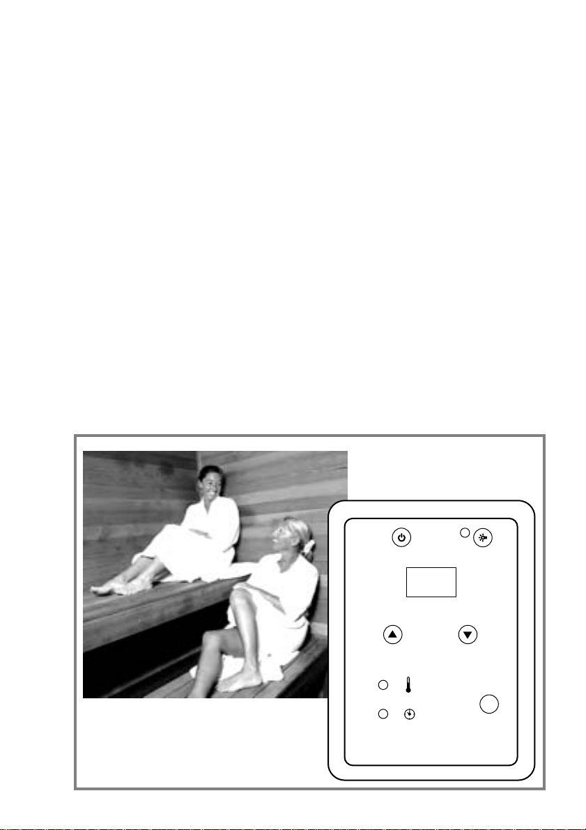
Infrarot-Steuerung
IHS 1 / IHF 1
Montageanweisung
Gebrauchsanweisung
60
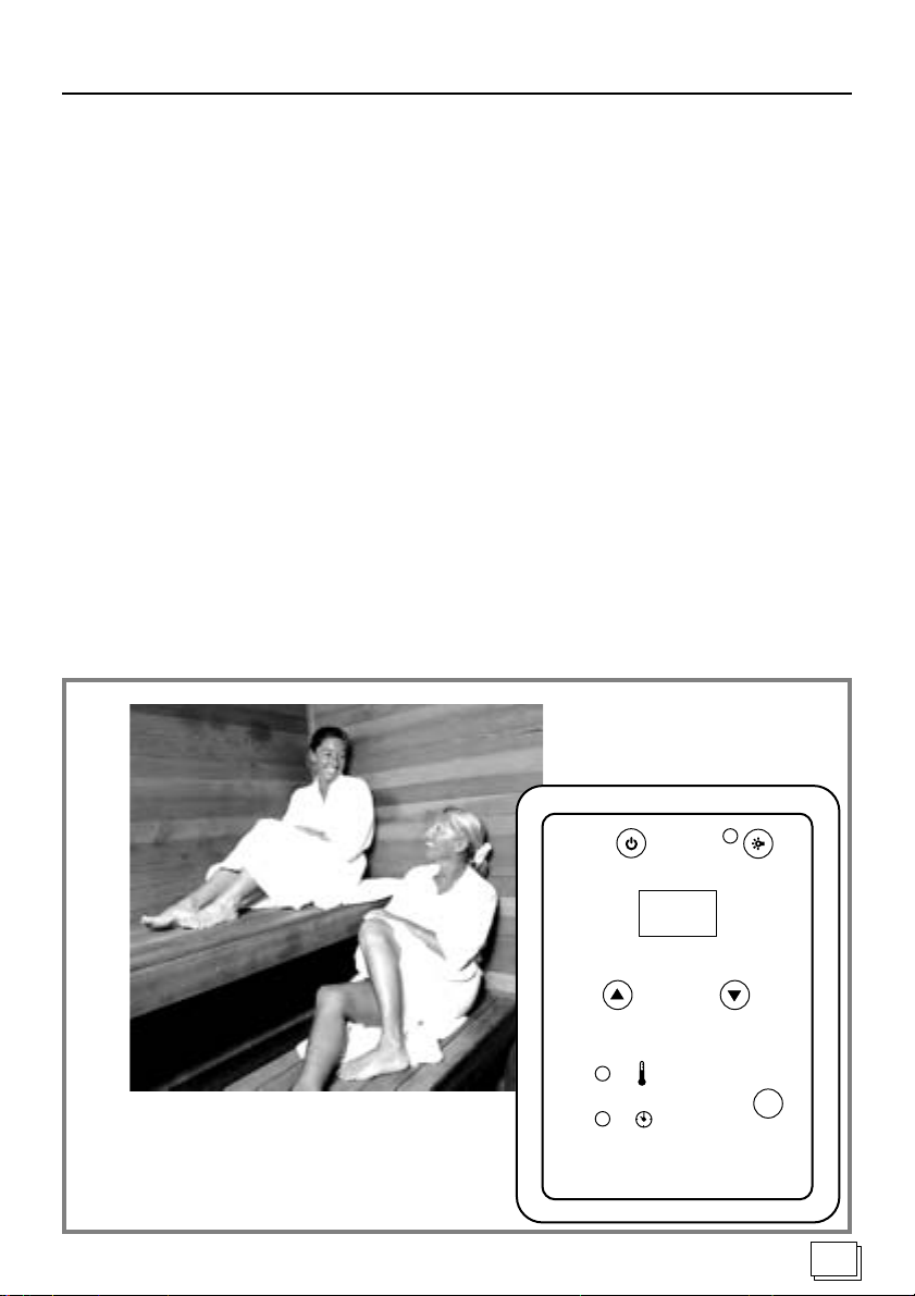
DEUTSCH 2 ENGLISH 9 FRANÇAIS 17 ITALIANO 25 NEDERLANDS 33
select
Page 2

Inhaltsverzeichnis
Teil 1 Montageanweisung nur für Fachpersonal
Allgemeine Sicherheitshinweise................................................................................................................. 3
1 Netzteil montieren ................................................................................................................................ 4
2 Bedienteil montieren ............................................................................................................................ 4
3 Innenraumtemperatur-Fühler montieren ............................................................................................. 5
4 Folientemperatur-Fühler montieren..................................................................................................... 5
Teil 2 Gebrauchsanweisung für den Benutzer
Allgemeine Sicherheitshinweise................................................................................................................. 6
1 Einstellungen und Bereiche................................................................................................................. 7
2 Zu Ihrer Sicherheit................................................................................................................................ 7
3 Fehlermeldungen ................................................................................................................................. 7
4 Bedienung ............................................................................................................................................ 7
5 Bei längeren Betriebspausen ............................................................................................................... 8
Teil 3 Technische Daten
Technische Daten........................................................................................................................................ 8
2
Page 3
Montageanweisung nur für Fachpersonal
Sehr geehrter Monteur
• Die Montage darf nur durch einen Elektrofachmann
oder einer vergleichsweise qualifizierten Person ausgeführt werden.
• Lesen Sie diese Montageanweisung sorgfältig vor
der Montage der Infrarot-Steuerung. Damit nutzen
Sie alle Vorteile, die das Gerät bietet und beugen
Schäden vor.
• Beim Auftreten besonderer Probleme, die in dieser
Montageanweisung nicht ausführlich genug behandelt werden, wenden Sie sich zu Ihrer eigenen Sicherheit an Ihren Lieferanten.
• Eigenmächtige Änderungen oder Umbauten an der
Infrarot-Steuerung sind aus Sicherheitsgründen
nicht gestattet.
• Technische Änderungen vorbehalten.
Bedeutung der in der Montageanweisung verwendeten Zeichen:
WARNUNG:
bei Nichtbeachtung besteht die Möglichkeit einer
schweren oder sogar tödlichen Verletzung.
VORSICHT:
bei Nichtbeachtung besteht die Möglichkeit von mittleren bis leichten Verletzungen oder Sachschäden.
Allgemeine Sicherheitshinweise
Beachten Sie auch die speziellen Sicherheitshinweise der einzelnen Kapitel.
Bestimmungsgemäßer Gebrauch:
• Die Infrarot-Steuerung dient zum Steuern und Regeln der Innenraumtemperatur:
- für Infrarot-Folien-Heizsysteme im Bereich von
30 - 50 Grad Celsius,
- für Infrarot-Stab-Heizsysteme im Bereich von
30 - 70 Grad Celsius.
• Die Infrarot-Steuerung darf nur zum Steuern und Regeln von 3 Heizkreisen mit maximal 1,2 kW Heizleistung pro Heizkreis eingesetzt werden.
Die Netzanschlussleitung ist mit 3 x 2,5
ren.
• Das Netzteil darf nur in Verbindung mit dem im Lieferumfang enthaltenen Bedienteil montiert und betrieben werden.
Entsorgung:
• Bitte entsorgen Sie die Verpackungsmaterialien
nach den gültigen Entsorgungsrichtlinien.
2
auszufüh-
HINWEIS:
gibt Anwendungstips und nützliche Informationen.
Entsorgung
Bewahren Sie diese Montageanweisung sorgfältig
in der Nähe der Infrarot-Steuerung auf, um jederzeit Sicherheitshinweise und wichtige Informationen nachschlagen zu können.
3
Page 4

Montageanweisung nur für Fachpersonal
1 Netzteil montieren
Abbildung 1
Das Netzteil wird auf die Kabinendecke oder die Kabinenwand oder gemäß der Herstellerempfehlung
montiert. Die elektrische Versorgung erfolgt mit einer
Netzanschlussleitung mit Schutzkontaktstecker (nicht
im Lieferumfang, nur als Zubehör erhältlich).
VORSICHT - Schäden am Gerät:
Das Netzteil an einem trockenen Ort montieren. Die
Umgebungsbedingungen von 40° Celsius und einer
maximalen Luftfeuchte von 95 Prozent einhalten.
1. Deckel 2 (mit vormontierter elektronischer Bau-
gruppe) des Netzteiles durch Herausschrauben
der vier Kreuzschlitzschrauben 4 x 12 mm lösen
und vorsichtig abnehmen.
2. Gehäuse 1 mit den beiliegenden vier Spanplat-
tenschrauben, 25 mm Länge, an die Kabinendekke oder die Kabinenwand anschrauben.
3. Deckel 2 wieder so auf das Gehäuse 1 mon-
tieren, dass die Anschlussstecker in den Gehäuseöffnungen liegen.
4. 10-polige Flachbandleitung 4 seitlich am Gehäu-
se auf den 10-poligen Steckverbinder 3 stecken.
VORSICHT - Schäden am Gerät:
Die Infrarot-Steuerung darf nur zum Steuern und Regeln von 3 Heizkreisen mit maximal 1,2 kW Heizleistung pro Heizkreis eingesetzt werden.
5. Das Anschliessen aller Komponenten am Netzteil 1
erfolgt gemäß Abbildung 1.
Die Stecker zum Anschliessen der Heizelemente und
der Kabinenbeleuchtung sind nicht im Lieferumfang
enthalten. Die entsprechenden Stecker ohne Leitung
sind als Zubehör erhältlich. (Stecksystem GST 18)
Heizelemente: Stecker schwarz
Kabinenbeleuchtung: Stecker kieselgrau
VORSICHT - Schäden am Gerät:
Zur Kühlung des Netzteiles muss eine freie Luftzirkulation möglich sein. Das Netzteil darf nicht durch
Gegenstände oder Materialien abgedeckt sein.
2 Bedienteil montieren
Abbildung 2
Das Bedienteil der Infrarot-Steuerung wird an der Kabinenaussenwand im maximalen Abstand von 3 Meter zum Netzteil montiert.
VORSICHT - Schäden am Gerät:
Das Bedienteil der Infrarot-Steuerung ist tropfwassergeschützt (Schutzgrad IP 43). Trotzdem darf das
Bedienteil nicht direkt mit Wasser in Berührung kommen.
Um den Schutzgrad IP 43 zu erzielen,
dienteil in der Kabinenwand versenkt montiert werden.
Das Bedienteil an einem trocken Ort montieren.
1. 25 mm tiefen Ausschnitt mit maximal 100 mm Brei-
te und maximal 156 mm Höhe in die Kabinenwand
schneiden.
2. Leitungsführungen für die Verbindungsleitungen
vorsehen.
3. Verriegelung mit einem Schraubendreher leicht
eindrücken und die Gehäuseabdeckung 4 abnehmen.
4. Gehäuse durch die Bohrungen 6 mit vier Span-
plattenschrauben an die Kabinenwand schrauben.
5. 10-poligen Stecker 5 der Flachbandleitung auf-
stecken.
6. 2-poligen Stecker 3 des Innenraumtemperatur-
Fühlers aufstecken.
Nur bei Heizstab-Heizsystem:
7. 2 PIN Jumper 1 (Steckerbrücke) im Bedienteil
abziehen.
Nur bei Folien-Heizsystem:
8. 3-poligen Stecker des Folientemperatur-Fühlers
2 aufstecken.
9. Leitungen der Folien- und Innenraumtemperatur-
Fühler zu den Montageorten führen.
10. 2 PIN Jumper 1 (Steckerbrücke) im Bedienteil
aufstecken.
HINWEIS - Konfigurieren der Varianten:
Gesteckter Jumper 1 = Folien-Heizsystem
Entfernter Jumper 1 = Heizstab-Heizsystem
muss das Be-
4
Page 5
Montageanweisung nur für Fachpersonal
3 Innenraumtemperatur-Fühler
montieren - Abbildung 3
Der Innenraumtemperatur-Fühler wird in der Saunakabine circa 30 cm unterhalb der Decke, oder nach
Angaben des Kabinen-Herstellers montiert.
Der maximale Abstand zum Bedienteil der InfrarotSteuerung soll 2 Meter nicht überschreiten.
VORSICHT - Zerstörung der Heizfolie:
Beim Infrarot-Folien-Heizsystem liegt die Heizfolie
direkt hinter der Saunawand.
Montieren Sie den Innenraumtemperatur-Fühler
nicht direkt über der Heizfolie.
VORSICHT - Falsche Messwerte:
Wird der Innenraumtemperatur-Fühler zu nahe an
die Heizung montiert, kommt es zu falschen Messwerten. Einen horizontalen Mindestabstand von circa 30 cm zur Heizung und circa 30 cm zur Kabinendecke einhalten.
Den Innenraumtemperatur-Fühler nicht über den Infrarot-Heizstäben montieren.
1. Innenraumtemperatur-Fühler 1 mit zwei Span-
plattenschrauben auf die Kabinenwand schrauben.
2. 2-polige Leitung 2 in der Kabinenwand verlegen
und mit Leitungsschellen fixieren.
4 Folientemperatur-Fühler
montieren - Abbildung 4
Der Folientemperatur-Fühler wird direkt an die Infrarot-Heizfolie montiert und mit einer Zugsicherung fixiert.
Der maximale Abstand zum Bedienteil der InfrarotSteuerung soll 2 Meter nicht überschreiten.
VORSICHT - Falsche Messwerte:
Wird der Folientemperatur-Fühler nicht direkt an die
Folie montiert, kommt es zu falschen Messwerten.
Den Folientemperatur-Fühler direkt an die Folie montieren.
HINWEIS:
Der Folientemperatur-Fühler wird nur beim Infrarot-Folien-Heizsystem benötigt.
1. Den Fühlerkopf 5 des Folientemperatur-Fühlers
1 direkt zwischen Dämmstoff und Heizfolie 4
montieren.
2. Folientemperatur-Fühler 1 mit der Zugentlastung
2 außerhalb des Folienbereiches fixieren.
3. 2-polige Leitung 3 in der Kabinenwand verlegen
und mit Leitungsschellen fixieren.
4. Je nach Ausführung des Heizsystems bzw. der
Kabine ist es erforderlich pro Heizkreis eine Übertemperatursicherung anzubringen und diese gemeinsam zum Leistungsteil zu führen.
Im Leistungsteil ist hierfür eine zweipolige Stiftleiste vorgesehen. Zuvor ist eventuell der aufgesteckte Jumper abzuziehen.
Nähere Angaben hierzu erfragen Sie bei Ihrem
Kabinenhersteller.
5
Page 6

Gebrauchsanweisung für den Anwender
Sehr geehrter Anwender
• Lesen Sie diese Gebrauchsanweisung sorgfältig vor
dem Gebrauch der Infrarot-Steuerung. Damit nutzen Sie alle Vorteile, die das Gerät bietet und beugen Schäden vor.
• Beim Auftreten besonderer Probleme, die in dieser
Gebrauchsanweisung nicht ausführlich genug behandelt werden, wenden Sie sich zu Ihrer eigenen
Sicherheit an Ihren Lieferanten.
• Eigenmächtige Änderungen oder Umbauten an der
Infrarot-Steuerung sind aus Sicherheitsgründen
nicht gestattet.
• Technische Änderungen vorbehalten.
Bedeutung der in der Gebrauchsanweisung verwendeten Zeichen:
WARNUNG:
bei Nichtbeachtung besteht die Möglichkeit einer
schweren oder sogar tödlichen Verletzung.
VORSICHT:
bei Nichtbeachtung besteht die Möglichkeit von mittleren bis leichten Verletzungen oder Sachschäden.
Allgemeine Sicherheitshinweise
Beachten Sie auch die speziellen Sicherheitshinweise der einzelnen Kapitel.
WARNUNG - Feuergefahr:
Vor dem Einschalten der Infrarot-Steuerung
ist sicher zu stellen, dass keine brennbaren
Gegenstände auf oder vor den IR-Heizstrahlern abgelegt sind.
Bestimmungsgemäßer Gebrauch:
• Die Infrarot-Steuerung dient zum Steuern und Regeln der Innenraumtemperatur:
- für Infrarot-Folien-Heizsysteme im Bereich von
30 - 50 Grad Celsius,
- für Infrarot-Stab-Heizsysteme im Bereich von
30 - 70 Grad Celsius.
• Die Infrarot-Steuerung darf nur zum Steuern und Regeln von 3 Heizkreisen mit maximal 1,2 kW Heizleistung pro Heizkreis eingesetzt werden.
• Das Netzteil darf nur in Verbindung mit dem im Lieferumfang enthaltenen Bedienteil montiert und betrieben werden.
HINWEIS:
gibt Anwendungstips und nützliche Informationen.
Feuergefahr
Entsorgung
Bewahren Sie diese Gebrauchsanweisung sorgfältig in der Nähe der Infrarot-Steuerung auf, um jederzeit Sicherheitshinweise und wichtige Informationen zur Bedienung nachschlagen zu können.
6
Entsorgung:
• Altgeräte enthalten wiederverwendbare Materialien. Geben Sie deshalb Altgeräte nicht einfach auf
die nächste Mülldeponie, sondern erkundigen Sie
sich bei Ihrer Stadt-oder Gemeindeverwaltung nach
der Möglichkeit der Wiederverwertung.
Page 7
Gebrauchsanweisung für den Anwender- Abbildung 5
1 Einstellungen und Bereiche
1.1 Was kann ich einstellen ?
• Die Innenraumtemperatur in Grad Celsius.
• Die Heizzeit in Minuten.
1.2 Welche Einstellbereiche habe ich ?
• Die Innenraumtemperatur kann beim:
- Infrarot-Folien-Heizsystem von 30 - 50 Grad Celsius,
- Infrarot-Stab-Heizsystem von 30 - 70 Grad Celsius
eingestellt werden.
• Die Heizzeit kann von 0 - 99 Minuten eingestellt
werden.
2 Zu Ihrer Sicherheit
VORSICHT - Schäden am Gerät:
Das Bedienteil der Infrarot-Steuerung darf nicht mit
Wasser übergossen oder sehr feucht gewischt werden. Benutzen Sie zum Reinigen ein leicht angefeuchtetes Reinigungstuch, das mit etwas milder Seifenlauge (Spülmittel) versehen ist.
3 Fehlermeldungen
Ein E_ mit einer Nummer in der Anzeige 1 signalisiert einen elektrischen Defekt der Infrarot-Steuerung
(siehe Technische Daten).
Die Infrarot-Steuerung ist nicht mehr betriebssicher:
• Ziehen Sie den Netzstecker 8.
• Verständigen Sie den Service.
• Kennzeichnen Sie das Gerät als defekt.
4 Bedienung
4.1 Die Infrarot-Steuerung einschalten
WARNUNG - Feuergefahr:
Vor dem Einschalten der Infrarot-Steuerung
ist sicher zu stellen, dass keine brennbaren
Gegenstände auf oder vor den IR-Heizstrahlern abgelegt sind.
1. Netzstecker des Netzteiles 8 in eine ordnungsgemäß geerdete Schutzkontakt-Steckdose einstecken.
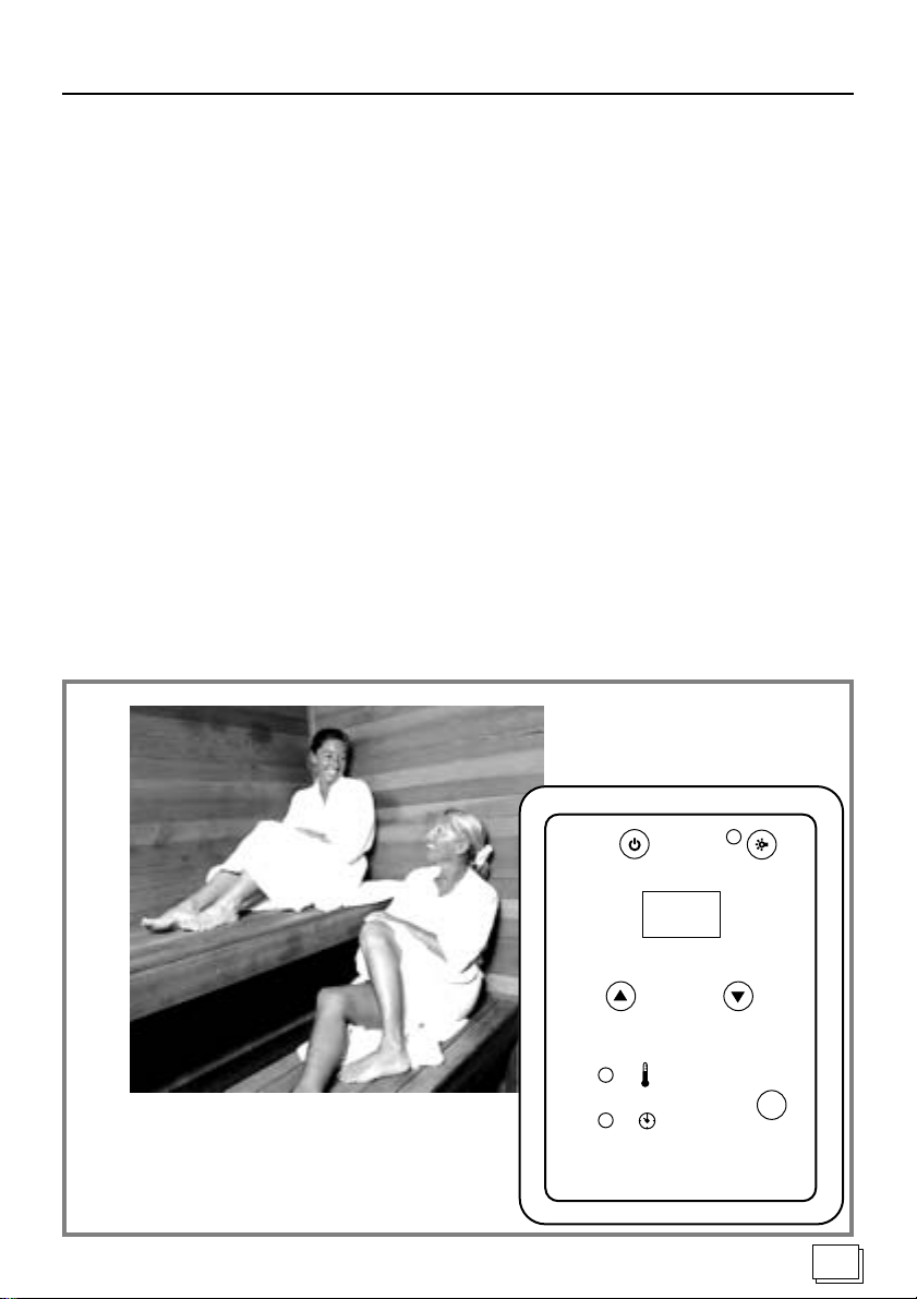
2. Infrarot-Steuerung am EIN / AUS Taster 1 einschalten.
In der Anzeige 3 erscheint die aktuelle Innenraumtemperatur.
4.2 Die Innenraumtemperatur einstellen
1. Wahltaster SELECT 5 drücken, bis die Leuchtanzeige TEMPERATUR 7 aufleuchtet.
In der Anzeige 3 erscheint die aktuelle Innenraumtemperatur.
HINWEIS:
Die Anzeige blinkt: Der Sollwert wird angezeigt.
Die Anzeige blinkt nicht: Die aktuelle Innenraumtemperatur wird angezeigt.
2. An den PLUS / MINUS T asten 4 den gewünsch-
ten Temperaturwert einstellen.
Die Anzeige 3 wechselt von der aktuellen Innenraumtemperatur zur Sollwertanzeige (Anzeige
blinkt).
3. Nach 5 Sekunden zeigt die Anzeige 3 wieder die
aktuelle Innenraumtemperatur (Anzeige 3 blinkt
nicht mehr).
Fortsetzung auf Seite 8.
7
Page 8
Gebrauchsanweisung für den Anwender- Abbildung 5
4 Bedienung (Fortsetzung)
4.3 Die Heizzeit einstellen
1. Wahltaster SELECT 5 drücken, bis die Leuchtanzeige HEIZZEIT 6 aufleuchtet.
In der Anzeige 3 erscheint 00.
2. An den PLUS / MINUS T asten 4 die gewünschte
Heizzeit einstellen.
Der Heizbetrieb startet. Die eingestellte Heizzeit
läuft rückwärts ab. Der rechte Dezimalpunkt blinkt
im Sekundentakt. Nach Ablauf der Heizzeit schaltet die Heizung ab. In der Anzeige 3 erscheinen
zwei Balken.
4.4 Die Infrarot-Steuerung ausschalten
1. Infrarot-Steuerung am EIN / AUS Taster 1 ausschalten.
4.5 Die Kabinen-Innenbeleuchtung ein- / aus-
schalten
1. Taste 2 schaltet die Kabinen-Innenbeleuchtung
EIN / AUS.
5 Bei längeren Betriebspausen
Netzstecker des Netzteiles 8 ziehen.
Technische Daten
Umgebungstemperatur: -10 °C bis + 40 °C
Lagertemperatur: -25 °C bis + 70 °C
Netzteil:
Abmessungen (B x H x T): 209 x 239 x 57 mm
Gewicht: ca. 1000 g
Nennspannung: 230 V AC; 50/60 Hz
Schaltleistung: AC1, 3 x 1,2 kW
Anschluss an das Versorgungsnetz mit einem bauseitigen Netzstecker.
Die Netzanschlussleitung ist mit 3 x 2,5
Bedienteil:
Abmessungen (B x H x T): 125 x 175 x 50 mm
Schutzart: IP 43 - Spritz-
Gewicht: ca. 180 g
Licht: AC1 = 1A
Einstellbereiche:
Temperatur Infrarot-Folien-Heizsystem:
30 - 50 Grad Celsius
Temperatur Infrarot-Stab-Heizsystem:
30 - 70 Grad Celsius
Heizzeitvorwahl: 00 - 99 Minuten
2
auszuführen.
wassergeschützt
Fehlermeldungen:
E1 Übertemperatursicherung hat abgeschaltet
E3 Fühlerleitungsbruch F1
E4 Fühlerleitungs-Kurzschluss F1
E5 Fühlerleitungs-Kurzschluss F2
E6 Fühlerleitungsbruch F2
E7 Übertemperaturfehler - Gerät vom Netz
trennen!
Ausgabe: 11-2007 Ident-Nr. 151 14 72
8
Page 9
ENGLISH
Infrared Control Unit IHS 1 / IHF 1
Assembling Instructions
Operating instructions
60
select
9
Page 10

Table of Contents
Part 1 Assembling Instructions for Specialist Staff Only
General Safety Information........................................................................................................................11
1 Mounting the power supply................................................................................................................ 12
2 Mounting the infrared control............................................................................................................. 12
3 Mounting the inside temperature sensor........................................................................................ ... 13
4 Mounting the foil temperature sensor................................................................................................ 13
Part 2 Operating instructions for the User
General Safety Information....................................................................................................................... 14
1 Settings and ranges ........................................................................................................................... 15
2 For your safety ................................................................................................................................... 15
3 Error messages .................................................................................................................................. 15
4 Operation............................................................................................................................................ 15
5 Pausing operation for a longer time period ....................................................................................... 16
Part 3 Technical Data
Technical data ........................................................................................................................................... 16
10
Page 11
Assembling Instructions for Specialist Staff Only
Dear Assembler
• Assembling may be performed by an electrician or
a comparatively qualified person only.
• Read the assembling instructions carefully, before
assembling the infrared control unit. By doing so you
will utilize all the benefits of the device and you will
prevent damages.
• Should particular problems occur, which are not suf-
ficiently dealt with in these assembling instructions,
to protect yourself, turn to your supplier.
• Unauthorized changes or modifications of the infra-
red control unit are not permitted due to safety reasons.
• We reserve the right to make technical changes.
Meaning of characters in the assembling instructions:
WARNING:
if not observed you may be subject to severe or even
deadly injury.
CAUTION:
if not observed you may be subject to medium to
light injuries or materials may be damaged.
General safety information
Follow the special safety information of each chapter.
As directed use:
• The infrared control unit is used to control the inside
temperature:
- for the infrared foil heating systems in the range of
30 - 50 degrees Celsius,
- for the infrared heating element systems in the range
of 30 - 70 degrees Celsius.
• Y ou are only allowed to use the infrared control unit
for controlling 3 heating circuits with a maximum
heating capacity of 1,2 kW per heating circuit.
The mains connection line must consist of 3 x 2,5².
• Only mount and operate the power supply unit with
the infrared control included in standard delivery.
Disposal:
• Please dispose of packaging materials in accordance with applicable disposal regulations.
NOTE:
gives advice concerning applications and useful information.
Disposal
Keep these assembling instructions near the infrared control unit for quick and easy reference regarding important information for safety and operation.
11
Page 12
Assembling Instructions for Specialist Staff Only
1 Mounting the power supply
Figure 1
Mount the power supply to the cabin ceiling or wall or
in accordance with manufacturer’s recommendations.
A power supply cord with an earthing pin plug (not
included in standard delivery) carries the electricity.
CAUTION - Damages of Device:
Mount the power supply unit at a dry location. With
environmental conditions of 40° Celsius and a maximum of 95 percent humidity.
1. Carefully remove the cover 2 (with pre- moun-
ted electronic component) of the power supply by
unscrewing the four recessed head screws 4 x 12
mm.
2. Fasten the housing 1 with the four, 25 mm long
wooden screws supplied, to the cabin ceiling or cabin wall.
3. Replace the cover 2 on the housing 1 so that
the connecting plugs are located in the housing
openings.
4. Guide the 10-pin flat stripwiring 4 into the 10-wire
socket 3 on the side of the housing.
CAUTION - Damages of Device:
You are only allowed to use the infrared control unit
for controlling 3 heating circuits with a maximum
heating capacity of 1,2 kW per heating circuit.
5. All of the components are connected to the power
supply 1 according to Figure 1.
The plugs for the connection of the heating elements and the cabin lighting are not included. The
appropriate plugs (without leads) are available as
accessories (plug system GST 18).
Heating elements: plug (black)
Cabin lighting: plug (silicon grey)
CAUTION - Damages of Device:
Allow free air circulation for the cooling of the power supply. The power supply may not be covered
by objects or materials.
2 Mounting the infrared control
Figure 2
Mount the infrared control to the outer cabin wall while
keeping a maximum distance of 3 meters to the power
supply unit.
CAUTION - Damages of Device:
The infrared control is drip-proof (degree of protection IP 43). Nevertheless, the infrared control may
not come in contact with water.
To attain the degree of protection of IP 43, the infrared control
Mount the infrared control at a dry location.
1. Cut a 25 mm deep opening with a maximum width
2. Provide wiring arrangements for the connection
3. Slightly push in the safety lock with a screwdriver
4. Through the bore holes 6 screw the housing with
5. Stick on 10-pin plug 5 of the flat band wiring.
6. Stick on 2-pinplug of the inside temperature sensor.
Applies to heating element systems only:
7. Pull off 2 PIN jumper 1 in the control unit.
Applies to foil heating systems only:
8. Stick on 3-pin plug of the foil temperature sensor 2.
9. Guide the lines of the foil and inside temperatu-
10. Stick on 2 PIN jumper 1 (connector jumper)
Plugged jumper 1 = foil heating system
Removed jumper 1 = heating element system
has to be recessed in the cabin wall.
of 100 mm and a maximum height of 156 mm in
the cabin wall.
lines.
and remove the upper housing cover 4.
four wooden screws to the cabin wall.
re sensors to the mounting locations.
control unit.
NOTE - Configuring the variants:
12
Page 13
Assembling Instructions for Specialist Staff Only
3 Mounting the inside temperature
sensor - Figure 3
Mount the inside temperature sensor in the sauna cabin, about 30 cm below the ceiling, or in accordance
with manufacturer specifications.
The maximum distance to the infrared control should
not exceed 2 meters.
CAUTION - Destruction of the heating foil:
The heating foil is located directly behind the sauna
wall of all infrared foil heating systems.
Do not mount the inside-temperature sensor directly above the heating foil.
CAUTION - Wrong measured values:
If the inside temperature sensor has been mounted
too close to the heater, it will indicate wrong measured values. Keep a minimum horizontal distance of
about 30 cm to the heater and about 30 cm to the
cabin ceiling.
Do not mount the inside temperature sensor above
the infrared heating elements.
1. Fasten the inside temperature sensor 1 with two
wooden screws to the cabin wall.
2. Run the 2-pin line 2 in the cabin wall and fasten
with wiring clips.
4 Mounting the foil temperature
sensor - Figure 4
Mount the foil temperature sensor directly to the infrared foil heating and fasten with a pull protection.
The maximum distance to the infrared control should
not exceed 2 meters
CAUTION - Wrong measured values:
If the foil temperature sensor has not been mounted
directly to the foil, it will indicate wrong measured
values.
Mount the foil temperature sensor directly to the foil.
NOTE:
The foil temperature sensor is only required in connection with infrared foil heating systems.
1. Mount the sensor head 5 of the foil temperature
sensor 1 directly between the insulating material and the heating foil 4.
2. Fasten the foil temperature sensor 1 with the
pull-relief 2 on the outside of the foil area.
3. Run the 2-pin line 3 in the cabin wall and fasten
with wiring clips.
4. Depending on the model of the heating system
and the cabin, per heating circuit it is necessary
to install an overtemperature fuse and connect it
together to the power unit. To do so, the power unit
has been equipped with a 2-pin plug connector.
If necessary, the mounted jumper may have to be
removed.
Y ou can obtain more information for this from your
cabin manufacturer.
13
Page 14
Operating instructions for the user
Dear User
• Carefully read the operating instructions before
using the infrared control unit.By doing so you will
utilize all the benefits of the device and you will
prevent damages.
• T o protect yourself, turn to your supplier should particular problems occur, which are not sufficiently
dealt with in these operating instructions.
• Unauthorized changes or modifications of the infrared control unit are not permitted due to safety reasons.
• We reserve the right to make technical changes.
Meaning of characters in the operating instructions:
WARNING:
if not observed you may be subject to severe or even
deadly injury.
CAUTION:
if not observed you may be subject to medium to
light injuries or materials may be damaged.
NOTE:
gives advice concerning applications and useful information.
Fire hazard
Disposal
General safety information
Follow the special safety information of each
chapter.
WARNING - Fire hazard:
Prior to turning on the sauna control make
sure that no combustible objects have been
placed on or in front of the IR radiant heaters.
As directed use:
• The infrared control unit is used to control the inside
temperature:
- for the infrared foil heating systems in the range of
30 - 50 degrees Celsius,
- for the infrared heating element systems in the range
of 30 - 70 degrees Celsius.
• Y ou are only allowed to use the infrared control unit
for controlling 3 heating circuits with a maximum
heating capacity of 1,2 kW per heating circuit.
• Only mount and operate the power supply unit with
the infrared control included in standard delivery.
Disposal:
• Old used devices contain recyclable materials.
Therefore please do not simply dispose of them at
the nearest landfill, but do inquire at the administrative offices of your city or district about the possibility of recycling.
Keep these operating instructions near the infrared
control unit for quick and easy reference regarding
important information for safety and operation.
14
Page 15
Operating instructions for the user - Figure 5
1 Settings and ranges
1.1 What can I adjust ?
• The inside temperature, measured in degrees of
Celsius.
• The heating time in minutes.
1.2 What are my ranges of adjustment ?
• The range of adjustment of the inside temperature
for:
- infrared foil heating systems is 30 - 50 degrees
Celsius,
- infrared heating element systems is 30 - 70 degrees Celsius.
• You can set the heating time for 0 - 99 minutes.
2 For your safety
CAUTION - Damages of Device:
Do not pour water on the infrared control unit or clean
it with a wet cloth.
For cleaning please use a cleaning cloth, which has
been slightly moistened with a mild soapy solvent
(dish detergent).
3 Error messages
4 Operation
4.1 Turn on the infrared control unit
WARNING - Fire hazard:
Prior to turning on the sauna control make
sure that no combustible objects have been
placed on or in front of the IR radiant heaters.
1. Plug the mains plug of the power supply 8 in a
properly grounded, ground contact outlet.
2. Turn on the infrared control unit with the ON / OFF
key 1.
The display 3 will indicate the current temperature of the inside.
4.2 How to set the inside temperature
1. Press option key SELECT 5, until the LED display TEMPERATURE 7 lights up.
The display 3 will indicate the current temperature of the inside.
NOTE:
The display flashes: The value desired is displayed.
The display does not flash: The current temperature
will be displayed.
The letter E_ with a number in the display 1 indicates an electrical defect of the infrared control unit (refer
to Technical Data).
The sauna control is no longer safe-to-operate:
• Pull the mains plug 8.
• Contact customer service.
• Mark the device as defective.
2. Set the desired temperature with the UP / DOWN
keys 4.
The display 3 will change from the current inside
temperature to the desired temperature (display
flashes).
3. After 5 seconds the display 3 will indicate the
current inside temperature again (display 3 no
longer flashes).
Continuation on page 16.
15
Page 16
Operating instructions for the user - Figure 5
4 Operation (Continued)
4.3 How to set the heating time
1. Press option key SELECT 5, until the LED display HEATING 6 lights up.
The display 3 indicates 00.
2. Set the desired heating time with the UP / DOWN
keys 4.
The heater starts up. The heating time set will
count down. The decimal point on the right flashes every second. After the heating time has
elapsed the heater will turn off. The display 3 will
indicate two bars.
4.4 How to turn off the infrared control unit
1. Turn off the infrared control unit with the ON / OFF
key 1.
4.5 How to turn on / off the interior cabin lighting
1. Key 2 turns the interior cabin lighting ON / OFF.
5 Pausing operation for a longer
time period
Pull the mains plug of the power supply 8.
Technical Data
Ambient temperature: -10°C to + 40°C
Storage temperature: -25°C to + 70°C
Power supply:
Dimensions (Wx H x D): 209 x 239 x 57 mm
Weight: approx. 1000 g
Nominal voltage: 230 VAC; 50/60 Hz;
Switching capacity: AC1, 3 x 1,2 kW
Connection to the supply system with a mains plug.
The mains connection line must consist of 3 x 2,5².
Infrared control:
Dimensions (Wx H x D): 125 x 175 x 50 mm
Type of protection: IP 43 - protection
from splashing water
Weight: approx. 180 g
Light: AC1 = 1A
Range of adjustment:
Temperature of the infrared foil heating system:
Temperature 30 - 50 degrees Celsius
Temperature of the infrared heating element system:
Temperature 30 - 70 degrees Celsius
Selection of heating time:
00 - 99 minutes
16
Error messages:
E1 Overtemperature fuse has switched off
E3 Break in sensor line F1
E4 Short in sensor line F1
E5 Short in sensor line F2
E6 Break in sensor line F2
E7 Error in overtemperature -
Disconnect the device from the power supply !
Edition: 11-2007 Ident-No. 151 14 72
Page 17
FRANÇAIS
Commande à infrarouge
IHS 1 / IHF 1
Instructions de montage
Instructions d’utilisation
60
select
17
Page 18

Table des matières
Partie 1 Instructions de montage pour les installateurs professionnels
Consignes de sécurité générales ............................................................................................................. 19
1 Montage du bloc d’alimentation......................................................................................................... 20
2 Montage du module de commande à infrarouge .............................................................................. 20
3 Montage de la sonde de température intérieure............................................................................... 21
4 Montage de la sonde de température d’écran .................................................................................. 21
Partie 2 Instructions d’utilisation pour l’utilisateur
Consignes de sécurité générales ............................................................................................................. 22
1 Réglages et plages de réglage.......................................................................................................... 23
2 Pour votre propre sécurité ................................................................................................................. 23
3 Messages d’erreur.............................................................................................................................. 23
4 Commande......................................................................................................................................... 23
5 En cas de temps d’arrêt prolongés.................................................................................................... 24
Partie 3 Spécifications techniques
Spécifications techniques ......................................................................................................................... 24
18
Page 19
Instructions de montage pour les installateurs professionnels
Cher Installateur,
• L’installation ne peut être réalisée que par un élec-
tricien ou toute autre personne disposant des qualifications similaires.
• Lisez attentivement les instructions de montage
avant de procéder à l’installation de la commande
à infrarouge. Vous pourrez ainsi tirer parti de tous
les avantages de l’appareil et éviter d’endommager
l’appareil.
• S’il se produit un problème qui n’est pas abordé de
façon suffisamment détaillée dans les présentes
instructions de montage, veuillez vous adresser à
votre fournisseur par mesure de sécurité.
• Toute modification ou transformation apportée par vos
soins à la commande à infrarouge est interdite.
• Sous réserve de modifications techniques.
Signification des symboles employés dans les instructions de montage:
AVERTISSEMENT :
Le non-respect des avertissements peut entraîner
de graves blessures.
Consignes de sécurité générales
Veuillez respecter les consignes de sécurité spécifiques de chaque chapitre.
Utilisation conforme:
• La commande à infrarouge sert à commander et à
régler la température intérieure:
- dans une plage de 30 à 50 degrés Celsius pour les
systèmes de chauffage à infrarouge à écrans;
- dans une plage de 30 à 70 degrés Celsius pour les
systèmes de chauffage à infrarouge à éléments.
• La commande à infrarouge ne peut être utilisée que
pour la commande et le réglage de trois circuits de
chauffage d’une puissance de chauffage maximale
de 1,2 kW par circuit de chauffage.
Le raccordement au secteur doit être réalisé avec
un câble de 3 x 2,5 mm².
• Le bloc d’alimentation ne peut être monté et employé que pour le module de commande à infrarouge
fourni.
Elimination:
ATTENTION :
Le non-respect de ces mises en garde peut entraîner des blessures légèrement à moyennement graves, ou des dommages matériels.
CONSEIL :
Les conseils fournissent des astuces d’utilisation
et des informations utiles.
Elimination
Conservez précieusement les présentes instructions de montage à proximité de la commande à
infrarouge de manière à pouvoir consulter ultérieurement les consignes de sécurité et d’autres
informations importantes.
• Veuillez éliminer les matériaux de conditionnement
conformément aux réglementations locales en vigueur.
19
Page 20
Instructions de montage pour les installateurs professionnels
1 Montage du bloc d’alimentation -
Illustrations 1
Le bloc d’alimentation doit être monté sur le plafond ou
la cloison de la cabine, ou suivant les instructions du fabricant. L’alimentation électrique est assurée au moyen
d’un câble secteur muni d’une fiche de sécurité (non fourni
et uniquement disponible en accessoire).
ATTENTION-Risques de dommages à l’appareil:
Le bloc d’alimentation doit être monté à un endroit
sec. Il importe de ne pas dépasser une température
ambiante de 40 ° Celsius et une humidité maximale
de 95 pour cent.
1. Desserrer et retirer le couvercle 2 (avec le mo-
dule électronique prémonté) du bloc d’alimentation
en dévissant les quatre vis cruciformes 4 x 12 mm.
2. Visser le boîtier 1 avec les quatre vis à bois de
25 mm de longueur fournies sur le plafond ou la
cloison de la cabine.
3. Réinstaller le couvercle 2 sur le boîtier 1 de fa-
çon à ce que les prises se placent dans les ouvertures du boîtier.
4. Introduire le câble plat à 10 pôles 4 dans le boî-
tier par l’ouverture de montage et le brancher sur
le connecteur enfichable à 10 pôles 3.
ATTENTION - Risques de dommages à l’appareil:
La commande à infrarouge ne peut être employée
que pour la commande et le réglage de trois circuits
de chauffage d’une puissance maximale de 1,2 kW
par circuit de chauffage.
5. Raccorder tous les composants du bloc
d’alimentation 1 conformément à l’illustration 1.
Les fiches de raccordement des éléments chauffants et pour l’éclairage de la cabine ne sont pas
fournies. Ces fiches sont disponibles en accessoires sans câblage (système de fiche GST 18).
Eléments chauffants: fiches noires
Eclairage de la cabine: fiches grises
ATTENTION - Risques de dommages à l’appareil:
Une circulation d’air libre doit être assurée pour garantir le refroidissement du bloc d’alimentation. Le
bloc d’alimentation ne doit en aucun cas être recouvert par des objets ou des matériaux quelconques.
20
2 Montage du module de comman-
de - Illustration 2
Le module de commande à infrarouge doit être monté
sur la cloison extérieure de la cabine à une distance
maximale de 3 mètres du bloc d’alimentation.
ATTENTION - Risques de dommages à l’appareil:
Le module de commande à infrarouge est étanche
aux projections d’eau (classe de protection IP 43).
La commande à infrarouge ne peut cependant pas
entrer directement en contact avec de l’eau. Pour
garantir la conformité de la classe de protection IP
43, le module de commande à infrarouge monté
affleurer à la surface de la cloison de la cabine.
Le module de commande à infrarouge doit être monté à un endroit sec.
1. Découper une ouverture de 25 mm de profondeur
et de maximum 100 mm de largeur et 156 mm de
hauteur dans la cloison de la cabine.
2. Prévoir des gaines à câbles pour les câbles de
raccordement.
3. Appuyer légèrement à l’aide d’un tournevis sur la
patte de verrouillage et retirer le couvercle du
boîtier 4.
4. Visser le boîtier sur la cloison de la cabine au
moyen de vis à bois en utilisant les quatre perçages 6 pratiqués dans le boîtier.
5. Brancher la fiche à 10 pôles 5 du câble plat.
6. Brancher la fiche à 2 pôles 3 de la sonde de tem-
pérature intérieure.
Pour le système de chauffage à éléments uniquement:
7. Débrancher le cavalier à 2 broches 1 (strap en-
fichable) du module de commande.
Pour le système de chauffage à écrans uniquement:
8. Brancher le cavalier à 3 broches de la sonde de
température d’écran 2.
9. Tirer les fils des sondes de température d’écran
et intérieure jusqu’au lieu de montage.
10. Brancher la fiche à 2 pôles 1 (strap enfichable).
CONSEIL - Configuration des variantes:
Cavalier enfiché 1 = système de chauffage à écrans
Cavalier non enfiché 1 = système de chauffage à
éléments
doit
Page 21
Instructions de montage pour les installateurs professionnels
3 Montage de la sonde de tempéra-
ture intérieure - Illustration 3
La sonde de température intérieure doit être montée
à l’intérieur de la cabine de sauna à environ 30 cm sous
le plafond, ou conformément aux instructions du fabricant de la cabine.
La distance maximale par rapport au module de commande à infrarouge ne peut pas dépasser 2 mètres.
ATTENTION - Risque de dommages aux
écrans chauffants:
Dans le cas d’un système de chauffage à infrarouge
à écran, l’écran chauffant est situé directement derrière la cloison du sauna.
Ne montez pas la sonde de température intérieure
directement au-dessus de l’écran chauffant.
ATTENTION - Risque d’erreur de valeurs de
mesure:
Si la sonde de température intérieure est montée trop
près du système de chauffage, il peut en résulter
des erreurs de mesure de la température. La sonde
de température intérieure doit être montée à une distance horizontale minimale d’environ 30 cm par rapport au chauffage et d’environ 30 cm du plafond de
la cabine.
La sonde de température intérieure ne peut pas être
montée au-dessus des éléments chauffants.
1. Visser la sonde de température intérieure 1 sur
la cloison de la cabine à l’aide de deux vis à bois.
2. Poser le câble à 2 pôles 2 dans la cloison de la
cabine et les fixer au moyen de brides de fixation.
4 Montage de la sonde de tempéra-
ture d’écran chauffant Illustration 4
La sonde de température d’écran chauffant doit être
montée directement sur l’écran chauffant à infrarouge
et fixée au moyen d’une décharge de traction.
La distance maximale par rapport au module de commande à infrarouge ne peut pas dépasser 2 mètres.
ATTENTION - Risque d’erreur de valeurs de
mesure:
Si la sonde de température intérieure n’est pas directement montée sur l’écran, il peut en résulter des
erreurs de mesure de la température. La sonde de
température d’écran doit être montée directement
sur l’écran chauffant.
CONSEIL:
La sonde de température d’écran est uniquement nécessaire dans le cas d’un système de chauffage à écran
à infrarouge.
1. Monter directement la tête de la sonde 5 de la
sonde de température d’écran 1 entre le matériau isolant et l’écran chauffant 4.
2. Fixer la sonde de température d’écran 1 avec la
décharge de traction 2 en dehors de la zone de
l’écran.
3. Tirer le câble à 2 pôles 3 dans la cloison de la
cabine et la fixer au moyen de brides de fixation.
4. Selon le modèle du système de chauffage ou de
la cabine, il peut être nécessaire d’installer une
protection de surchauffe par circuit de chauffage
et de les raccorder au bloc d’alimentation. Le bloc
d’alimentation doit pour cela comporter une barrette à broches à 2 pôles. Il convient éventuellement de débrancher le cavalier au préalable.
Pour des informations complémentaires à ce sujet,
prendre contact avec le fabricant de la cabine.
21
Page 22
Instructions d’utilisation pour l’utilisateur
Cher Utilisateur,
• Veuillez lire attentivement les instructions d’utilisation
avant d’employer la commande à infrarouge. Vous
pourrez ainsi tirer parti de tous les avantages de
l’appareil et éviter de l’endommager.
• S’il se produit un problème qui n’est pas abordé de
façon suffisamment détaillée dans les présentes
instructions d’utilisation, veuillez vous adresser à
votre fournisseur par mesure de sécurité.
• Toute modification ou transformation apportée par
vos soins à la commande à infrarouge est interdite pour des raisons de sécurité.
• Sous réserve de modifications techniques.
Signification des symboles employés dans les
instructions de montage:
AVERTISSEMENT:
Le non-respect de ces mises en garde peut entraîner de graves blessures.
ATTENTION:
Le non-respect de ces mises en garde peut entraîner des blessures légèrement à moyennement graves, ou des dommages matériels.
CONSEIL:
Les conseils fournissent des astuces d’utilisation
et des informations utiles.
Risque d’incendie
Consignes de sécurité générales
Veuillez respecter les consignes de sécurité spécifiques de chaque chapitre.
AVERTISSEMENT - Risque d’incendie:
Avant la mise sous tension de la commande à infrarouge, s’assurer qu’il n’y a pas
d’objets inflammables au-dessous ou devant le radiateur IR.
Utilisation conforme:
• La commande à infrarouge sert à commander et à
régler la température intérieure:
- dans une plage de 30 à 50 degrés Celsius pour les
systèmes de chauffage à infrarouge à écrans;
- dans une plage de 30 à 70 degrés Celsius pour les
systèmes de chauffage à infrarouge à éléments.
• La commande à infrarouge ne peut être utilisée que
pour la commande et le réglage de trois circuits de
chauffage d’une puissance de chauffage maximale
de 1,2 kW par circuit de chauffage.
• Le bloc d’alimentation ne peut être monté et employé que pour le module de commande à infrarouge
fourni.
Elimination:
• Les appareils usagés contiennent des matériaux
recyclables. Par conséquent, ne jetez pas les appareils usagés avec les ordures ménagères, mais
renseignez-vous auprès de l’administration de votre
ville ou région sur les possibilités de recyclage.
Elimination
Conservez précieusement les présentes instructions de montage à proximité de la commande à
infrarouge de manière à pouvoir consulter ultérieurement les consignes de sécurité et d’autres
informations importantes.
22
Page 23
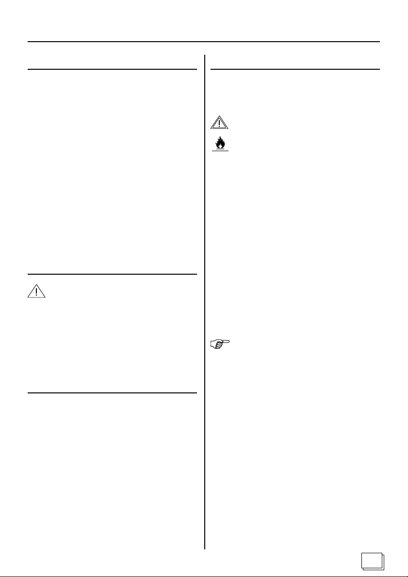
Instructions d’utilisation pour l’utilisateur - Illustration 5
1 Réglages et plages de réglage
1.1 Que puis-je régler?
• La température intérieure en degrés Celsius.
• Le temps de chauffage en minutes.
1.2 Quelles sont les plages de réglages utilisables?
• La température intérieure peut être réglée:
- dans une plage de 30 à 50 degrés Celsius pour
les systèmes de chauffage à infrarouge à écrans;
- dans une plage de 30 à 70 degrés Celsius pour
les systèmes de chauffage à infrarouge à éléments.
• Le temps de chauffage peut être réglé dans une
page de 0 à 99 minutes.
2 Pour votre sécurité
ATTENTION - Risques de dommages à
l’appareil :
Le module de commande à infrarouge ne peut pas
être plongé dans l’eau ni être nettoyé avec un chiffon mouillé. Pour le nettoyage du module de commande à infrarouge, utilisez un chiffon légèrement
imprégné d’une solution détergente neutre (détergent à vaisselle).
3 Messages d’erreur
4 Utilisation
4.1 Mise sous tension de la commande à infrarouge
AVERTISSEMENT - Risque d’incendie:
Avant la mise sous tension de la commande à infrarouge, s’assurer qu’il n’y a pas
d’objets inflammables au-dessous ou devant le radiateur IR.
1. Brancher la fiche secteur du bloc d’alimentation
8 sur une prise de courant mise à la terre en parfait état.
2. Mettre la commande à infrarouge sous tension à
l’aide de l’interrupteur MARCHE/ARRET 1.
La température intérieure instantanée apparaît
dans la fenêtre d’affichage 3.
4.2 Réglage de la température intérieure
1. Appuyer sur le sélecteur SELECT 5 jusqu’à ce
que le témoin TEMPERATURE 7 s’allume.
La température intérieure instantanée apparaît
dans la fenêtre d’affichage 3.
CONSEIL:
L’affichage clignote: la valeur programmée est affichée.
L’affichage ne clignote pas: la température intérieure instantanée est affichée.
Si la lettre E_ suivie d’un numéro apparaît dans la
fenêtre d’affichage 1, cela signifie qu’une défaillance
électrique s’est produite dans la commande à infrarouge (voir Spécifications techniques).
La commande à infrarouge n’offre plus toute la
sécurité d’utilisation voulue:
• Débrancher la fiche d’alimentation secteur 8.
• Avertir le service après-vente.
• Signaler l’appareil comme défectueux.
2. Appuyer sur les touches PLUS / MOINS 4 pour
régler la température voulue.
L’affichage 3 passe de la température intérieure instantanée à la température programmée
(l’affichage clignote).
3. Au bout de 5 secondes, l’affichage 3 revient à
la température intérieure instantanée (l’affichage
3 ne clignote plus).
23
Page 24
Instructions d’utilisation pour l’utilisateur - Illustration 5
4 Utilisation
4.3 Réglage du temps de chauffage
1. Appuyer sur le sélecteur SELECT 5 jusqu’à ce
que le témoin TEMPS DE CHAUFFAGE 6
s’allume.
La valeur 00 apparaît dans l’affichage 3.
2. Régler la durée voulue à l’aide des touches PLUS
/ MOINS 4.
Le compte à rebours démarre et le chauffage commence. Le point décimal de droite clignote de
seconde en seconde. Au terme de la durée programmée, le chauffage se coupe et deux traits
apparaissent dans l’affichage 3.
4.4 Mise hors tension de la commande à infra-
rouge
1. Mettre la commande à infrarouge hors tension à
l’aide de l’interrupteur MARCHE / ARRET 1.
4.5 Mise sous/hors tension de l’éclairage de la
cabine
1. La touche MARCHE /ARRET 2 commande la
mise sous/hors tension de l’éclairage de la cabine.
5 En cas de temps d’arrêt prolongé
Débrancher la fiche d’alimentation secteur du bloc
d’alimentation 8.
Spécifications techniques
Température ambiante: -10 à + 40 °C
Température de stockage: -25 à + 70 °C
Bloc d’alimentation:
Dimensions (l x h x p): 209 x 239 x 57 mm
Poids: env. 1 000 g
Tension nominale: 230 V CA ; 50/60 Hz
Puissance de coupure: AC1, 3 x 1,2 kW
Raccordement au secteur via un bloc d’alimentation
vous incombant (non fourni).
Le raccordement au secteur doit être réalisé avec un
câble de 3 x 2,5 mm².
Module de commande:
Dimensions (l x h x p) : 125 x 175 x 50 mm
Classe de protection: IP 43 - Etanche aux
projections d’eau
Poids: env. 180 g
Eclairage: AC1 = 1 A
Plages de réglage:
Système de chauffage à infrarouge à écrans :
30 à 50 degrés Celsius
Système de chauffage à infrarouge à éléments :
30 à 70 degrés Celsius
Présélection du temps de chauffage :
0 à 99 minutes
24
Messages d’erreur :
E1 Déclenchement de la protection de surchauffe
E3 Coupure du fil de la sonde F1
E4 Court-circuit du fil de la sonde F1
E5 Court-circuit du fil de la sonde F2
E6 Coupure du fil de la sonde F2
E7 Sonde de température de surchauffe - Dé
brancher l’appareil du secteur !
Edition: 11-2007 N° d’ident. 151 14 72
Page 25
ITALIANO
Controllo a infrarossi
IHS 1 / IHF 1
Istruzioni per il montaggio
Istruzioni per l’uso
60
select
25
Page 26

Indice
Parte 1 Istruzioni per il montaggio solo per il personale specializzato
Indicazioni generali sulla sicurezza.......................................................................................................... 27
1 Montare l’alimentatore ....................................................................................................................... 28
3 Montare il sensore della temperatura all’interno della sauna........................................................... 28
4 Montare il sensore della temperatura del foglio................................................................................29
Parte 2 Istruzioni per l’uso per l’utente
Indicazioni generali sulla sicurezza.......................................................................................................... 30
1 Impostazioni e intervalli ...................................................................................................................... 31
2 Per la vostra sicurezza....................................................................................................................... 31
3 Messaggi d’errore............................................................................................................................... 31
4 Uso...................................................................................................................................................... 31
5 Pause prolungate di funzionamento.................................................................................................. 32
Parte 3 Dati tecnici
Dati tecnici................................................................................................................................................. 32
26
Page 27
Istruzioni per il montaggio solo per il personale specializzato
Caro montatore,
• Il montaggio può essere eseguito solo da un elet-
tricista specializzato o da una persona con una qualifica equivalente.
• Legga queste istruzioni per il montaggio con cura
prima di effettuare il montaggio del controllo a infrarossi. Così facendo sarà possibile usufruire di tutti
i vantaggi che l’apparecchio offre ed evitare danni.
• Nel caso si verifichino problemi particolari, che non
sono stati trattati in modo esauriente in queste istruzioni per il montaggio, per la propria sicurezza, Si
rivolga al proprio fornitore.
• Modifiche o cambiamenti non autorizzati sul cont-
rollo a infrarossi non sono consentiti per motivi di
sicurezza.
• Con riserva di modifiche tecniche.
Significato dei simboli utilizzati nelle istruzioni per
il montaggio:
AVVERTIMENTO:
in caso di inosservanza c’è la possibilità di un ferimento grave o addirittura mortale.
Indicazioni generali sulla sicurezza
Osservare anche le indicazioni speciali sulla sicurezza dei singoli capitoli.
Uso conforme:
• Il controllo a infrarossi serve a controllare e regolare la temperatura all’interno della sauna:
- Per il sistema di riscaldamento del foglio, a infrarossi,
nell’intervallo di
30 - 50 gradi Celsius,
- per il sistema di riscaldamento della sbarra, a infrarossi, nell’intervallo
30 - 70 gradi Celsius,
Il controllo a infrarossi può essere utilizzato per con-
trollare e regolare 3 circuiti di riscaldamento con una
potenzialità calorifera massima di 1,2 kW per circuito.
Eseguire la linea di allacciamento alla rete con
2
3 x 2,5
.
• L’alimentatore può essere montato ed utilizzato solo
in collegamento al controllo contenuto nella fornitura.
ATTENZIONE:
in caso di inosservanza c’è la possibilità di un ferimento da medio a leggero o di danni agli oggetti.
NOTA:
dà consigli per l’applicazione ed informazioni utili.
Smaltimento
Conservare con cura queste istruzioni per il montaggio vicino al controllo a infrarossi, per poter
raggiungere in qualsiasi momento le indicazioni
sulla sicurezza e le informazioni importanti.
Smaltimento:
• Smaltire i materiali dell’imballo secondo le direttive
per lo smaltimento in vigore.
27
Page 28
Istruzioni per il montaggio solo per il personale specializzato
1 Montare l'alimentatore
Figura 1
Montare l’alimentatore sul soffitto della cabina o sulla
parete della cabina o secondo le indicazioni del costruttore.
L’alimentazione elettrica ha luogo con una linea di allacciamento alla rete con spina con messa a terra (non nella
fornitura, ottenibile solo come accessorio).
ATTENZIONE - Danni all'apparecchio:
Montare l’alimentatore in un luogo asciutto. Le condizioni ambientali devono essere di 40° Celsius con
un’umidità massima dell’aria del 95 percento.
1. Allentare il coperchio 2 (con gruppo elettronico
premontato) dell’alimentatore svitando le quattro
viti con impronta a croce 4 x 12 mm e toglierlo con
cautela.
2. Avvitare il contenitore 1 con le quattro viti di legno
allegate di 25 mm di lunghezza, sul tetto della cabina o avvitarlo alla parete della cabina.
3. Rimontare il coperchio 2 sul contenitore 1 in
modo che i connettori si trovino nelle aperture del
contenitore.
4. Inserire il cavo piatto a 10 poli 4 lateralmente nel
contenitore sul connettore a 10 poli 3.
ATTENZIONE - Danni all'apparecchio:
Il controllo a infrarossi può essere utilizzato per controllare e regolare 3 circuiti di riscaldamento con una
potenzialità calorifera massima di 1,2 kW per circuito.
5. Effettuare l’allacciamento di tutti i componenti
all’alimentatore 1 secondo la figura 1.
I connettori per allacciare i riscaldatori e l’illuminazione
della cabina non sono contenuti nella fornitura. Le
spine relative senza linea si possono ricevere come
accessorio (plug system GST 18).
Riscaldatori: Connettore a spina nero.
Illuminazione cabina: Connettore a spina grigio silice.
2 Montare l'unità di controllo
Figura 2
Montare l’unità di controllo del controllo a infrarossi
sulla parete esterna della cabina ad una distanza
massima di 3 metri dall’alimentatore.
ATTENZIONE - Danni all'apparecchio:
L’unità di controllo del controllo a infrarossi è protetta contro lo stillicidio (grado di protezione IP 43).
Ciononostante l’unità di controllo non deve entrare
in contatto diretto con l’acqua.
Per ottenere il grado di protezione IP 43, l’unità di
controllo
rete della cabina.
Montare l’unità di controllo in un luogo asciutto.
1. Tagliare un’apertura profonda 25 mm con
2. Provvedere alle guide per le linee di collegamento.
3. Premere leggermente il bloccaggio con un caccia-
4. Avvitare il contenitore attraverso i fori 6 con
5. Inserire la spina a 10 poli 5 del cavo piatto.
6. Inserire la spina a 2 poli 3 del sensore della tem-
Solo su sistemi di riscaldamento con riscaldatore a immersione:
7. Sfilare i 2 PIN Jumper 1 (ponticelli) nell’unità di
Solo su sistemi di riscaldamento con foglio:
8. Inserire la spina a 3 poli del sensore della tempe-
9. Introdurre le linee del sensore della temperatura
10. Inserire i 2 PIN Jumper 1 (ponticelli) nell’unità di
deve essere montata incassata nella pa-
un’ampiezza di 100 mm al massimo e 156 mm di
altezza al massimo nella parete della cabina.
vite e togliere la copertura del contenitore 4.
quattro viti de legno alla parete della cabina.
peratura all’interno della sauna.
controllo.
ratura del foglio 2.
del foglio e all’interno della sauna fino ai luoghi di
montaggio.
controllo.
ATTENZIONE - Danni all'apparecchio:
Per raffreddare l’alimentatore deve essere possibile
una libera circolazione dell’aria. L’alimentatore non
deve essere coperto da oggetti o materiali.
28
NOTA - Configurare le varianti:
Jumper inserito 1 = Sistema di riscaldamento a fogli
Jumper rimosso 1 = Sistema di riscaldamento con
riscaldatore a immersione
Page 29
Istruzioni per il montaggio solo per il personale specializzato
3 Montare il sensore della tempera-
tura all'interno della sauna Figura 3
Il sensore della temperatura all’interno della sauna
viene montato nella cabina della sauna a circa 30 cm
dal soffitto, o secondo le indicazioni del costruttore della
cabina.
La distanza massima dall’unità di controllo del controllo a infrarossi non deve superare i 2 metri.
ATTENZIONE - Distruzione del foglio riscaldante:
Sul sistema di riscaldamento con fogli a infrarossi,
il foglio riscaldante si trova direttamente dietro alla
parete della sauna.
Montare il sensore della temperatura all’interno della sauna non direttamente sopra foglio riscaldante.
ATTENZIONE - Valori misurati sbagliati:
Se il sensore della temperatura all’interno della sauna viene montato troppo vicino al riscaldamento, si
ottengono valori misurati sbagliati. Osservare una
distanza orizzontale minima di circa 30 cm dal riscaldamento e circa 30 cm dal soffitto della cabina.
Non montare il sensore della temperatura all’interno
della sauna sopra al riscaldatore a immersione a
infrarossi.
1. Avvitare il sensore della temperatura all’interno
della sauna 1 con due viti de legno sulla parete della cabina.
2. Collocare la linea a 2 poli 2 nella parete della
cabina e fissarla con delle fascette.
4 Montare il sensore della tempera-
tura del foglio - Figura 4
Il sensore della temperatura del foglio viene montato
direttamente sul foglio di riscaldamento a infrarossi e
fissato con una protezione.
La distanza massima dall’unità di controllo del controllo a infrarossi non deve superare i 2 metri.
ATTENZIONE - Valori misurati sbagliati:
Se il sensore della temperatura del foglio non viene
montato direttamente sul foglio, si ottengono valori
misurati sbagliati.
Montare il sensore della temperatura del foglio direttamente sul foglio.
NOTA:
Il sensore della temperatura del foglio è necessario solo
su un sistema di riscaldamento con foglio a infrarossi.
1. Montare la testa del sensore 5 del sensore della
temperatura del foglio 1 direttamente tra il materiale isolante ed il foglio riscaldante 4.
2. Fissare il sensore della temperatura del foglio 1
con scarico della trazione 2 all’esterno della zona
del foglio.
3. Collocare la linea a 2 poli 3 nella parete della
cabina e fissarla con delle fascette.
4. A seconda del modello del sistema di riscaldamen-
to o della cabina è necessario installare, su ogni
circuito di calore, un fusibile di sovratemperatura
e collegarlo all’unità di potenza.
Nell’unità di potenza è previsto un connettore a
due poli. Prima di questo estrarre eventualmente il jumper inserito.
Potrà ottenere maggiori indicazioni a questo riguardo dal costruttore della vostra cabina.
29
Page 30
Istruzioni per l'uso per l'utente
Caro utente
• Legga queste istruzioni per l’uso con cura, prima di
utilizzare il controllo a infrarossi. Così facendo sarà
possibile usufruire di tutti i vantaggi che
l’apparecchio offre ed evitare danni.
• Nel caso si verifichino particolari problemi, che in
queste istruzioni per l’uso non sono stati trattati in
modo esauriente, per la propria sicurezza, Si rivolga
al proprio fornitore.
• Modifiche o cambiamenti non autorizzati sul controllo a infrarossi non sono consentiti per motivi di
sicurezza.
• Con riserva di modifiche tecniche.
Significato dei simboli utilizzati nelle istruzioni per
l’uso:
AVVERTIMENTO:
in caso di inosservanza c’è la possibilità di un ferimento grave o addirittura mortale.
ATTENZIONE:
in caso di inosservanza c’è la possibilità di un ferimento da medio a leggero o di danni agli oggetti.
NOTA:
dà consigli per l’applicazione ed informazioni utili.
Indicazioni generali sulla sicurezza
Osservare anche le indicazioni speciali sulla sicurezza dei singoli capitoli.
AVVERTIMENTO - Pericolo d'incendio:
Prima di accendere il controllo a infrarossi
assicurarsi che nessun oggetto infiammabile sia collocato sopra o davanti ai raggi
IR.
Uso conforme:
• Il controllo a infrarossi serve a controllare e regolare la temperatura all’interno della sauna:
- Per il sistema di riscaldamento a infrarossi del foglio nell’intervallo di
30 - 50 gradi Celsius,
- per il sistema di riscaldamento con sbarra, a infrarossi, nell’intervallo
30 - 70 gradi Celsius,
• Il controllo a infrarossi può essere utilizzato per controllare e regolare 3 circuiti di riscaldamento con una
potenzialità calorifera massima di 1,2 kW per circuito.
• L’alimentatore può essere montato ed utilizzato solo
in collegamento all’alimentatore contenuto nella
fornitura.
Pericolo d'incendio
Smaltimento
Conservare con cura queste istruzioni per l’uso
vicino al controllo a infrarossi, per poter raggiungere in qualsiasi momento le indicazioni sulla sicurezza e le informazioni importanti per l’uso.
30
Smaltimento:
• Gli apparecchi usati contengono materiali riutilizzabili. Non getti quindi gli apparecchi usati semplicemente nella discarica di rifiuti più vicina, ma Si informi, presso l’amministrazione della Sua città o del
Suo comune, circa la possibilità di riciclaggio.
Page 31
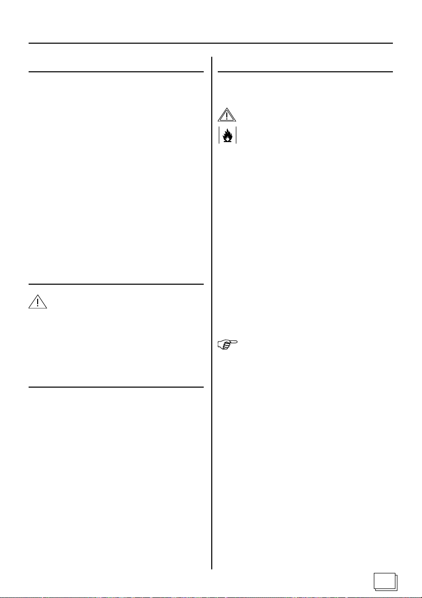
Istruzioni per l'uso per l'utente - Figura 4
1 Impostazioni e intervalli
1.1 Che cosa posso impostare?
• La temperatura all’interno della sauna in gradi
Celsius.
• Il tempo di riscaldamento in minuti.
1.2 Che intervalli di regolazione ho?
• La temperatura all’interno della sauna può essere
impostata:
- sul sistema di riscaldamento con foglio a infrarossi
dai 30 ai 50 gradi Celsius,
- sul sistema di riscaldamento con asta a infrarossi
dai 30 ai 70 gradi Celsius.
• Il tempo di riscaldamento può essere impostato
da Die Heizzeit kann von a 99 minuti.
2 Per la vostra sicurezza
ATTENZIONE - Danni all'apparecchio:
Non versare acqua sull’unità di comando del controllo a infrarossi nè strofinarla con un panno molto
umido. Per pulire utilizzare un panno di pulizia leggermente imbevuto con un detergente delicato (detersivo per piatti).
3 Messaggi d'errore
Una E_ con un numero sul display 1 segnala un
difetto elettrico del controllo a infrarossi (vedi dati tecnici).
Il controllo a infrarossi non è più sicuro per funzionare:
• Tirare il connettore di rete 8.
• Informare il servizio assistenza.
• Contrassegnare l’apparecchio come difettoso.
4 Uso
4.1 Accendere il controllo a infrarossi
AVVERTIMENTO - Pericolo d'incendio:
Prima di accendere il controllo a infrarossi
assicurarsi che nessun oggetto infiammabile sia collocato sopra o davanti ai raggi
IR.
1. Inserire il connettore di rete dell’alimentatore 8
in una presa regolarmente collegata a terra con
contatto di terra.
2. Accendere il controllo a infrarossi con il tasto ON/
OFF 1.
Sul display 3 compare la tempratura attuale
all’interno della sauna.
4.2 Impostare la temperatura interna
1. Premere il tasto di scelta SELECT 5, finchè la
spia luminosa TEMPERATURA 7 si accende.
Sul display 3 compare la tempratura attuale
all’interno della sauna.
NOTA:
Il display lampeggia: viene indicato il valore nominale.
Il display non lampeggia: viene indicata la temperatura attuale all’interno della sauna.
2. Impostare la temperatura desiderata con i tasti
PIÙ/MENO 4.
Il display 3 passa dalla visualizzazione della
temperatura interna attuale alla visualizzazione del
valore nominale (il display lampeggia).
3. Dopo 5 secondi il display 3 indica di nuovo la
temperatura attuale all’interno della sauna (display
3 non lampeggia più).
Continua a pagina 32.
31
Page 32
Istruzioni per l'uso per l'utente - Figura 5
4 Uso (continua)
4.3 Impostare il tempo di riscaldamento.
1. Premere il tasto di scelta SELECT 5, finchè la
spia luminosa TEMPO DI RISCALDAMENTO 6
si accende.
Sul display 3 compare 00.
2. Impostare il tempo di riscaldamento desiderato
con i tasti PIÙ/MENO 4.
Il riscaldamento si avvia. Il tempo di riscaldamento
impostato scorre alla rovescia. Il punto decimale
sulla destra lampeggia ogni secondo. Al termine
del tempo di riscaldamento il riscaldamento si
spegne. Sul display 3 compaiono due barre.
4.4 Spegnere il controllo a infrarossi
1. Spegnere il controllo a infrarossi con il tasto ON/
OFF 1.
4.5 Accendere/spegnere l’illuminazione interna
della cabina
1. Il tasto 2 accende/spegne l’illuminazione
all’interno della cabina ON / OFF.
5 Pause prolungate di funzionamento
Tirare il connettore di rete dell’alimentatore 8.
Dati tecnici
Temperatura ambiente: da -10°C a + 40°C
T emperatura d’immagazzinamento: da -25°C a + 70°C
Alimentatore:
Dimensioni (L x A x P): 209 x 239 x 57 mm
Peso: ca. 1000 g
Tensione nominale: 230 V AC; 50/60 Hz
Potere di rottura: AC1, 3 x 1,2 kW
Allacciamento alla rete di alimentazione con un connettore di rete.
Eseguire la linea di allacciamento alla rete con 3 x 2,5
Unità di controllo:
Dimensioni (L x A x P): 125 x 175 x 50 mm
Grado di protezione: IP 43 - Protezione
dagli schizzi d’acqua
Peso: ca. 180 g
Luce: AC1 = 1A
Intervalli di regolazione:
Temperatura del sistema di riscaldamento a fogli e
infrarossi: 30 - 50 gradi Celsius,
Temperatura del sistema di riscaldamento ad aste e
infrarossi: 30 - 70 gradi Celsius,
Preselezione del tempo di riscaldamento:
00 - 99 minuti
2
.
32
Messaggi d’errore:
E1 Il fusibile di sovratemperatura si è staccato
E3 Rottura nella linea del sensore F1
E4 Cortocircuito nella linea del sensore F1
E5 Cortocircuito nella linea del sensore F2
E6 Rottura nella linea del sensore F2
E7 Errore di sovratemperatura - Separare
l’apparecchio dalla rete!
Edizione: 11-2007 N. ident. 151 14 72
Page 33
NEDERLANDS
Infraroodbesturing IHS 1 / IHF 1
Installatiehandleiding
Gebruiksaanwijzing
60
select
33
Page 34

Inhoud
Deel 1 Installatiehandleiding enkel voor vaklui
Algemene veiligheidsvoorschriften........................................................................................................... 35
1 Installatie van de voedingseenheid ................................................................................................... 36
2 Installatie van het bedieningselement ............................................................................................... 36
3 Installatie van de binnentemperatuursensor.....................................................................................37
4 Installatie van de folietemperatuursensor ......................................................................................... 37
Deel 2 Gebruiksaanwijzing voor de gebruiker
Algemene veiligheidsvoorschriften........................................................................................................... 38
1 Instellingen en niveaus ...................................................................................................................... 39
2 Voor uw veiligheid .............................................................................................................................. 39
3 Foutmeldingen.................................................................................................................................... 39
4 Bediening............................................................................................................................................ 39
5 Bij langdurig niet-gebruik ................................................................................................................... 40
Deel 3 Technische gegevens
Technische gegevens ............................................................................................................................... 40
34
Page 35
Installatiehandleiding enkel voor vaklui
Beste installateur,
• Deze besturing mag enkel geïnstalleerd worden
door een elektricien of door een persoon die over
een vergelijkbare kennis beschikt.
• Lees deze installatierichtlijnen zorgvuldig door voo-
raleer de infraroodbesturing te installeren. Op die
manier benut u alle voordelen van dit apparaat en
vermijdt u eventuele schade.
• Indien zich bijzondere problemen voordoen die
onvoldoende behandeld worden in deze handleiding, richt u dan voor uw eigen veiligheid tot uw
leverancier.
• Uit veiligheidsoverwegingen is het niet toegestaan
zelf wijzigingen of aanpassingen aan te brengen aan
de infraroodbesturing.
• Onder voorbehoud van technische wijzigingen.
Betekenis van de symbolen in deze installatiehandleiding:
WAARSCHUWING:
Bij niet-naleving kunt u ernstig gewond raken.
OPGELET:
Bij niet-naleving kunt u matige tot lichte verwondingen oplopen of kan het materiaal beschadigd raken.
Algemene veiligheidsvoorschriften
Gelieve ook de speciale veiligheidsvoorschriften
per hoofdstuk te lezen.
Reglementair gebruik:
• De infraroodbesturing dient voor het bedienen en
regelen van de binnentemperatuur:
- van infrarood folieverwarmingssystemen tussen
30 - 50 graden Celsius,
- van infrarood staafverwarmingssystemen tussen
30 - 70 graden Celsius.
• De infraroodbesturing mag enkel gebruikt worden
voor de bediening en regeling van 3 verwarmingscircuits met een maximale verwarmingscapaciteit
van 1,2 kW per verwarmingscircuit.
Voor de aansluiting op het stroomnet moet een
netkabel van 3 x 2,5² gebruikt worden.
• Installeer en gebruik de voedingseenheid alleen in
combinatie met het origineel geleverde bedieningselement.
Verwijdering van afval:
• Verwijder het verpakkingsmateriaal volgens de
geldende richtlijnen voor afvalverwijdering.
TIP:
Toepassingstips en nuttige informatie.
Verwijdering van afval
Bewaar deze installatierichtlijnen zorgvuldig bij de
infraroodbesturing zodat u op elk ogenblik snel en
makkelijk de veiligheidsrichtlijnen en andere belangrijke informatie kunt raadplegen.
35
Page 36
Installatiehandleiding enkel voor vaklui
1 Installatie van de voedingseen-
heid - afbeelding 1
De voedingseenheid wordt geïnstalleerd aan het plafond
of tegen de wand van de cabine of volgens de richtlijnen
van de fabrikant. De elektrische voeding wordt verzekerd
via een netkabel naar de voedingseenheid met veiligheidsstekker (niet meegeleverd, enkel verkrijgbaar als optie).
OPGELET – Schade aan het apparaat:
Installeer de voedingseenheid steeds op een droge
plaats, waarbij u ervoor zorgt dat de omgevingscondities van 40° Celsius en een maximale luchtvochtigheid van 95 procent nageleefd worden.
1. Behuizing 2 (met vooraf geïnstalleerde elektro-
nische module) van de voedingseenheid losmaken en verwijderen door de 4 kruiskopschroeven
4 x 12 mm los te schroeven.
2. Behuizing 1 met de meegeleverde 4 Hout-
schroeven van 25 mm lang bevestigen aan het
plafond of tegen de wand van de cabine.
3. Behuizing 2 zodanig opnieuw monteren op be-
huizing 1 dat de netstekkers in de behuizingsopeningen passen.
4. 10-pins bandkabel 4 aan de zijkant van de be-
huizing vastmaken aan de 10-pinsconnector 3.
OPGELET – Schade aan het apparaat:
De infraroodbesturing mag enkel gebruikt worden
voor de bediening en regeling van 3 verwarmingscircuits met een maximale verwarmingscapaciteit
van 1,2 kW per warmtecircuit.
5. De aansluiting van alle componenten op de voe-
dingseenheid 1 verloopt volgens afbeelding 1.
De stekkers voor de aansluiting van de verwarmingselementen en de cabineverlichting worden niet meegeleverd. De respectieve stekkers zonder kabel zijn
als optie verkrijgbaar (stekkersysteem GST 18).
Verwarmingselementen: zwarte stekker
Cabineverlichting: kiezelgrijze stekker
OPGELET – Schade aan het apparaat:
Er moet een vrije luchtcirculatie mogelijk zijn zodat
de voedingseenheid voldoende gekoeld wordt. Bovendien mag de voedingseenheid niet bedekt worden door voorwerpen of materialen.
36
2 Installatie van het bedieningsele-
ment - afbeelding 2
Het bedieningselement van de infraroodbesturing wordt
geïnstalleerd aan de buitenwand van de cabine op een
maximale afstand van 3 meter van de voedingseenheid.
OPGELET – Schade aan het apparaat:
Het bedieningselement van de infraroodbesturing
is spatwaterdicht (beschermingsgraad IP 43). Toch
mag het bedieningselement niet rechtstreeks met
water in contact komen.
Om de beschermingsgraad IP 43 te verkrijgen,
het bedieningselement in de cabinewand ingewerkt
worden.
Het bedieningselement op een droge plaats installeren.
1. Snijd een opening in de cabinewand van 25 mm
diep met een maximale breedte van 100 mm en
een maximale hoogte van 156 mm.
2. Voorzie kabeltrajecten voor de verbindingskabels.
3. Druk de vergrendeling lichtjes in met een schroe-
vendraaier en verwijder de behuizingkap 4.
4. Schroef de behuizing met 4 Hout-schroeven door
de boorgaten 6 vast aan de cabinewand.
5. 10-pinsstekker 5 van de bandkabel inpluggen.
6. 2-pinsstekker 3 van de binnentemperatuursensor
inpluggen.
Enkel van toepassing bij een staafverwarmingssysteem:
7. 2-pinsjumpers 1 (geleiderbrug) uit het bediening-
selement verwijderen.
Enkel van toepassing bij een folieverwarmingssysteem:
8. 3-pinsstekker van de folietemperatuursensor 2
inpluggen.
9. Kabels van de folie- en binnentemperatuursensor
naar de installatieplaatsen leiden.
10. 2-pinsjumpers 1 (geleiderbrug) in het bediening-
selement inpluggen.
TIP – configuratie van de varianten:
Aanwezige jumper 1 = folieverwarmingssysteem
Verwijderde jumper 1 = staafverwarmingssysteem
moet
Page 37
Installatiehandleiding enkel voor vaklui
3 Installatie van de binnentempera-
tuursensor - afbeelding 3
De binnentemperatuursensor wordt in de saunacabine
ongeveer 30 cm onder het plafond gemonteerd of volgens de richtlijnen van de cabinefabrikant. De maximale afstand tot het bedieningselement van de infraroodbesturing mag niet meer dan 2 meter bedragen.
OPGELET – Beschadiging van de verwarmingsfolie:
Bij een infrarood folieverwarmingssysteem bevindt
de verwarmingsfolie zich onmiddellijk achter de saunawand.
Installeer de binnentemperatuursensor niet direct
boven de verwarmingsfolie.
OPGELET – Verkeerde meetwaarden:
Als de binnentemperatuursensor te dicht bij de verwarming geïnstalleerd is, worden verkeerde meetwaarden weergegeven. Respecteer steeds een horizontale minimumafstand van ongeveer 30 cm tot
de verwarming en ongeveer 30 cm tot het cabineplafond.
Monteer de binnentemperatuursensor niet boven de
infrarood verwarmingselementen.
1. Binnentemperatuursensor 1 met 2 Hout-schroe-
ven aan de cabinewand vastmaken.
2. 2-pinskabel 2 in de cabinewand inwerken en
vastmaken met draadbeugels.
4 Installatie van de folietemperatu-
ursensor - afbeelding 4
De folietemperatuursensor wordt rechtstreeks op de
infrarood verwarmingsfolie gemonteerd en met een
trekbeveiliging vastgemaakt. De maximale afstand tot
het bedieningselement van de infraroodbesturing mag
niet meer dan 2 meter bedragen.
OPGELET – Verkeerde meetwaarden:
Als de folietemperatuursensor niet rechtstreeks op
de folie gemonteerd is, worden verkeerde meetwaarden weergegeven. De folietemperatuursensor moet
rechtstreeks op de folie gemonteerd worden.
TIP:
De folietemperatuursensor is enkel nodig bij een infrarood folieverwarmingssysteem.
1. De sensorkop 5 van de folietemperatuursensor
1 rechtstreeks tussen het isolatiemateriaal en de
verwarmingsfolie 4 monteren.
2. De folietemperatuursensor 1 met de snoerklem
2 vastmaken aan de buitenkant van de locatie
waar de folie zit.
3. 2-pinskabel 3 in de cabinewand inwerken en met
draadbeugels vastmaken.
4. Naar gelang de uitvoering van het verwarmings-
systeem of de cabine wordt per warmtecircuit best
een oververhittingsveiligheid aangebracht, die dan
met de voedingseenheid verbonden wordt. Daarvoor is in de voedingseenheid een 2-pinsconnector
voorzien. Eventueel moet de ingeplugde jumper
eerst uitgetrokken worden.
Verdere informatie hierover kunt u verkrijgen bij
uw cabinefabrikant.
37
Page 38
Gebruiksaanwijzing voor de gebruiker
Beste gebruiker,
• Lees deze gebruiksaanwijzing zorgvuldig door vooraleer de infraroodbesturing te gebruiken. Op die
manier benut u alle voordelen van dit apparaat en
vermijdt u eventuele schade.
• Indien zich bijzondere problemen voordoen die
onvoldoende behandeld worden in deze handleiding, richt u dan voor uw eigen veiligheid tot uw
leverancier.
• Uit veiligheidsoverwegingen is het niet toegestaan
zelf wijzigingen of aanpassingen aan te brengen aan
de infraroodbesturing.
• Onder voorbehoud van technische wijzigingen.
Betekenis van de symbolen in deze gebruiksaanwijzing:
WAARSCHUWING:
Bij niet-naleving kunt u ernstig gewond raken.
OPGELET:
Bij niet-naleving kunt u matige tot lichte verwondingen oplopen of kan het materiaal beschadigd raken.
TIP:
Toepassingstips en nuttige informatie.
Brandgevaar
Verwijdering van afval
Bewaar deze gebruiksaanwijzing zorgvuldig bij de
infraroodbesturing zodat u op elk ogenblik snel en
makkelijk de veiligheidsrichtlijnen en andere belangrijke informatie met betrekking tot de bediening kunt raadplegen.
Algemene veiligheidsvoorschriften
Gelieve ook de speciale veiligheidsvoorschriften
per hoofdstuk te lezen.
WAARSCHUWING - Brandgevaar:
Vooraleer u de infraroodbesturing inschakelt, moet u erop letten dat er zich op of vlak
voor de verwarmingselementen geen brandbaar materiaal bevindt.
Reglementair gebruik:
• De infraroodbesturing dient voor het bedienen en
regelen van de binnentemperatuur:
- van infrarood folieverwarmingssystemen tussen
30 - 50 graden Celsius,
- van infrarood staafverwarmingssystemen tussen
30 - 70 graden Celsius.
• De infraroodbesturing mag enkel gebruikt worden
voor de bediening en regeling van 3 verwarmingscircuits met een maximale verwarmingscapaciteit
van 1,2 kW per verwarmingscircuit.
• Installeer en gebruik de voedingseenheid alleen in
combinatie met het origineel geleverde bedieningselement.
Verwijdering van afval:
• Gebruikte apparaten bevatten recycleerbaar materiaal. Gooi gebruikte apparaten dus ook niet zomaar
weg op de stortplaats, maar vraag inlichtingen bij
uw stads- of gemeentebestuur over eventuele recyclingmogelijkheden.
38
Page 39
Gebruiksaanwijzing voor de gebruiker - afbeelding 5
1 Instellingen en niveaus
1.1 Wat kan ik instellen?
• De binnentemperatuur in graden Celsius.
• De verwarmingstijd in minuten.
1.2 Wat zijn de mogelijke instelniveaus?
• Volgende instellingen zijn mogelijk voor de binnentemperatuur:
- voor het infrarood folieverwarmingssysteem: van
30 - 50 graden Celsius,
- voor het infrarood staafverwarmingssysteem: van
30 - 70 graden Celsius.
• De opwarmingstijd kan ingesteld worden van 0 99 minuten.
2 Voor uw veiligheid
OPGELET – Schade aan het apparaat:
Het bedieningselement van de infraroodbesturing
mag niet met water overgoten of heel vochtig gereinigd worden.
Om het apparaat te reinigen gebruikt u best een doek
die licht bevochtigd is met een zacht zeepmiddel
(afwasproduct).
3 Foutmeldingen
4 Bediening
4.1 De infraroodbesturing inschakelen
WAARSCHUWING - Brandgevaar:
Vooraleer u de infraroodbesturing inschakelt, moet u erop letten dat er zich op of vlak
voor de verwarmingselementen geen brandbaar materiaal bevindt.
1. Netstekker van de voedingseenheid 8 in een reglementair geaard veiligheidsstopcontact inpluggen.
2. Infraroodbesturing inschakelen via de AAN/UITtoets 1.
Het display 3 geeft de actuele binnentemperatuur weer.
4.2 De binnentemperatuur instellen
1. SELECT-toets 5 indrukken tot het verklikkerlichtje
TEMPERATUUR 7 oplicht.
Het display 3 geeft de actuele binnentemperatuur weer.
TIP:
Het display knippert: de gewenste temperatuur wordt
weergegeven.
Het display knippert niet: de actuele binnentemperatuur wordt weergegeven.
Wanneer in het display 1 een letter E_ gevolgd door
een nummer verschijnt, duidt dit op een elektrisch
defect in de infraroodbesturing (zie technische gegevens).
De infraroodbesturing is niet langer bedrijfszeker:
• Trek de stekker uit het stopcontact 8.
• Contacteer de klantendienst.
• Geef duidelijk aan dat het apparaat defect is.
2. Via de PLUS/MIN-toetsen 4 de gewenste tem-
peratuur ingeven.
Het display 3 schakelt van de actuele binnentemperatuur over naar de gewenste temperatuur (display begint te knipperen).
3. Na 5 seconden geeft het display 3 opnieuw de
actuele binnentemperatuur weer (display 3 stopt
met knipperen).
39
Page 40
Gebruiksaanwijzing voor de gebruiker - afbeelding 5
4 Bediening
4.3 De opwarmingstijd instellen
1. SELECT-toets 5 indrukken tot het verklikkerlichtje
OPWARMINGSTIJD 6 oplicht.
In het display 3 verschijnt de waarde 00.
2. Via de PLUS/MIN-toetsen 4 de gewenste opwarmingstijd instellen.
De opwarming start en de ingestelde opwarmingstijd telt af. Het decimale punt rechts knippert met
de seconden mee. Zodra de opwarmingstijd voorbij is, wordt de verwarming uitgeschakeld. In het
display 3 verschijnen 2 balkjes.
4.4 De infraroodbesturing uitschakelen
1. Infraroodbesturing met de AAN/UIT-toets 1 uitschakelen.
4.5 De verlichting in de cabine in- en uitschakelen
1. Via toets 2 schakelt u de cabineverlichting AAN/
UIT.
5 Bij langdurig niet-gebruik
Stekker uit de voedingseenheid 8 trekken.
Technische gegevens
Omgevingstemperatuur: -10 °C tot +40 °C
Opslagtemperatuur: -25 °C tot +70 °C
Voedingseenheid:
Afmetingen (B x H x D): 209 x 239 x 57 mm
Gewicht: ca. 1000 g
Nominale spanning: 230 V AC; 50/60 Hz
Afschakelvermogen: AC1, 3 x 1,2 kW
Aansluiting op het stroomnet met een ingebouwde
stekker.
Voor de aansluiting op het stroomnet moet een netkabel van 3 x 2,5² gebruikt worden.
Bedieningselement:
Afmetingen (B x H x D): 125 x 175 x 50 mm
Beschermingsklasse: IP 43 – spatwater
dicht
Gewicht: ca. 180 g
Licht: AC1 = 1A
Instelniveaus:
Temperatuur infrarood folieverwarmingssysteem:
30 - 50 graden Celsius
Temperatuur infrarood staafverwarmingssysteem:
30 - 70 graden Celsius
Instelling opwarmingstijd:
00 - 99 minuten
40
Foutmeldingen:
E1 de oververhittingsveiligheid is uitgeschakeld
E3 breuk in sensorleiding F1
E4 kortsluiting in sensorleiding F1
E5 kortsluiting in sensorleiding F2
E6 breuk in sensorleiding F2
E7 oververhittingsfout – stekker uit het stopcon
tact halen!
Versie: 11-2007 Ident-Nr. 151 14 72
 Loading...