

Page 1
VI350
Instruction Manual
English Version1.0
VI350 EXPANDABLE
VIDEO DOORPHONE
SYSTEM
(WITH HANDS-FREE INTERCOM)
Copyright © 2006 Lorex Technology Inc www.homesentinel.com
Page 2

Table of Contents
FCC Class B Notice......................................................................................................................3
1 Safety Warnings and Precautions.........................................................................................4
1.1 Important Safety Instructions.........................................................................................4
1.2 Warnings.......................................................................................................................5
1.2.1 Explanation of Symbols.........................................................................................5
1.3 Precautions ...................................................................................................................6
2 Introduction ...........................................................................................................................7
2.1 System Contents...........................................................................................................7
2.2 Features........................................................................................................................7
3 The Video Doorphone System..............................................................................................8
3.1 The Monitor Station.......................................................................................................8
3.2 Monitor Terminal Connections ....................................................................................10
3.3 The Doorphone Camera..............................................................................................12
3.4 Camera Terminal Connections....................................................................................13
4 Installation...........................................................................................................................15
4.1 Additional Door Camera Set-up ..................................................................................16
4.2 Video Doorphone Operation........................................................................................16
5 Video Doorphone Expansion Options.................................................................................18
5.1 The MO 350 Monitor ...................................................................................................19
5.1.1 MO 350 Monitor Installation ................................................................................22
5.1.2 MO 350 Monitor Operation..................................................................................22
5.2 The CA 350 Outdoor Camera .....................................................................................23
5.2.1 CA 350 Outdoor Camera Installation...................................................................23
5.2.2 CA 350 Outdoor Camera Operation....................................................................23
5.2.3 The Door Release Function ................................................................................23
6 Troubleshooting Guide........................................................................................................25
7 Specifications......................................................................................................................26
8 APPENDIX #1.....................................................................................................................27
8.1 Connect Electric Door Strike or Magnetic Lock (optional)...........................................27
9 APPENDIX 2.......................................................................................................................29
9.1 Connect the Video Doorphone System with Existing Wiring.......................................29
Page 2 of 31 VI350-MANUAL-EN.R1.doc
Page 3

FCC Class B Notice
This equipment has been certified and found to comply with the limits regulated by
FCC, EMC and LVD. Therefore, it is designed to provide reasonable protection
against interference and will not cause interference with other appliance usage.
However, it is imperative that the user follows this manual's guidelines to avoid
improper usage which may result in damage to the unit, electrical shock and fire
hazard or injury. In order to improve the feature functions and quality of this product,
the specifications are subject to change without notice from time to time.
This equipment has been tested and found to comply with the limits For a Class B
digital device, pursuant to Part 15 of the FCC Rules. These limits are designed to
provide reasonable protection against harmful interference in a residential
installation. This equipment generates, Uses and can radiate radio frequency
energy and, if not installed and used in accordance with the instruction, may cause
harmful interference to radio communications. However, there is no guarantee that
interference will not occur in a particular installation. If this equipment does cause
harmful interference to radio or television reception, (which can be determined by
turning the equipment off and on), the user is encouraged to try to correct the
interference by one or more of the following measures:
• Re-orient or relocate the monitor unit
• Increase the separation between the monitor and camera.
• Connect the equipment on a separate outlet
• Consult the dealer or an experienced radio or television technician for help
Page 3 of 31 VI350-MANUAL-EN.R1.doc
Page 4

1 Safety Warnings and Precautions
1.1 Important Safety Instructions
WARNING
TO REDUCE THE RISK OF FIRE OR ELECTRIC SHOCK
DO NOT EXPOSE THIS APPLIANCE OR POWER
ADAPTER TO WATER OR MOISTURE
Read Instructions – All the safety and operating instructions should be read before
operating this equipment. These instructions should be retained for future reference
Heed Warnings – All warnings on the equipment and in the operating instructions
should be adhered to. All instructions regarding care and operation of this equipment
should be followed.
Power Sources – Equipment should only be connected to the power supply
specified in the operating instructions or as marked on the equipment.
Power-Cord Protection – Keep cable cords and plugs clear of other objects,
particularly at the point where they exit the equipment.
Cleaning – Clean the equipment by wiping with a soft cloth, (do not use any
abrasive agents or water).
Non-use Periods – Power cords should be unplugged from the outlet when left
unused for a long period of time.
Object and Liquid Entry – Take care not to drop objects or liquids on any part of
the equipment.
Damage Requiring Service – The unit should be serviced by a qualified service
personnel when:
• The power-supply cord or the plug has been damaged; or
• Objects have fallen, or liquid has been spilled onto the equipment; or
• The equipment has been exposed to rain; or
• The equipment does not appear to operate normally or exhibits a
• marked change in performance; or
• The equipment has been dropped, and/or the enclosure has
• been damaged
Page 4 of 31 VI350-MANUAL-EN.R1.doc
Page 5
Servicing – Do not attempt to service the appliance beyond that described in the
operating instructions. All other servicing should be referred to a Qualified
Distributor’s Service Personnel.
1.2 Warnings
CAUTION
RISK OF ELECTRIC SHOCK
TO REDUCE THE RISK OF ELECTRIC SHOCK, DO NOT
REMOVE COVER (OR BACK) NO USER-SERVICEABLE
PARTS INSIDE. REFER SERVICING TO QUALIFIED
SERVICE PERSONNEL
1.2.1 Explanation of Symbols
The lightning flash with arrowhead symbol, within an equilateral triangle,
is intended to alert the user to the presence of un-insulated "dangerous
voltage" within the product's enclosure that may be of sufficient
magnitude to constitute a risk of electric shock to persons.
The exclamation point within an equilateral triangle is intended to alert the
user to the presence of important operating and maintenance (servicing)
instructions in the literature accompanying the appliance.
NOTE THE GRAPHIC SYMBOLS WITH SUPPLEMENTAL MARKING ARE ON THE
BOTTOM OF THE SYSTEM.
WARNING
TO PREVENT FIRE OR SHOCK HAZARD
DO NOT EXPOSE THE UNIT TO RAIN OR MOISTURE
Page 5 of 31 VI350-MANUAL-EN.R1.doc
Page 6

1.3 Precautions
• Use only the power adapter supplied with the system. The use of any other
power adapter may cause damage to the system which is not covered under
warranty.
• Keep it dry. If water should get on it, wipe it off immediately. Water contains
minerals that can corrode electronic circuits.
• Do not use or store in area of high levels of dirt or dust. The electronic circuit
may be contaminated, and any moving parts will wear prematurely.
• Avoid installing the monitor directly into the sun or in any other intensely bright
locations.
• Do not install the monitor in areas where it may be exposed to excessive
moisture or extreme temperatures.
• Do not install near corrosive chemicals or harmful gases.
• Before installing the system completely, it is a good idea to check for proper
operation by temporarily connecting the monitor to the camera and powering
up units.
Page 6 of 31 VI350-MANUAL-EN.R1.doc
Page 7

2 Introduction
Thank you for purchasing the Home Sentinel Video Doorphone entry system. This
model allows you to identify and communicate with callers at the door, from the
security and convenience of any room in your home. Visitors activate the system by
pressing a call button on the outdoor camera, which sounds a doorbell chime as well
as turning on the inside video monitor. A 2-way audio intercom then lets you speak
with visitors after first visually identifying them. It consists of a monitor station and an
outdoor camera unit. Expansion is possible to include up to 4 monitors and 2 outdoor
camera stations.
For proper usage and application, please read the instruction manual completely.
2.1 System Contents
• Monitor Station • 65 ft. Cable
• AC adapter • Owner’s Manual
• Outdoor Camera Station
• Mounting Hardware Kit
2.2 Features
• High definition 4" flat screen CRT
• Hands free with 2 way audio intercom between outdoor camera stations and
monitors
• Expansion camera setup
• Auto shut off after 30 seconds for unanswered calls and 90 seconds for
answered calls
• Remote door open function (requires optional electric door strike)
• High resolution 1/3" B/W CCD image sensor camera
• Wide angle lens with auto iris adjustments
• Infrared illumination for clear night vision ( 0 lux) at close range
• The system can be expanded with up to 4 monitors and up to 2 outdoor camera
units.
Page 7 of 31 VI350-MANUAL-EN.R1.doc
Page 8
L1 L2
3 The Video Doorphone System
The video doorphone system is designed to identify and commnunicate with callers
at the door from the security of your home.
The Monitor Station and Camera are the main components of the system.
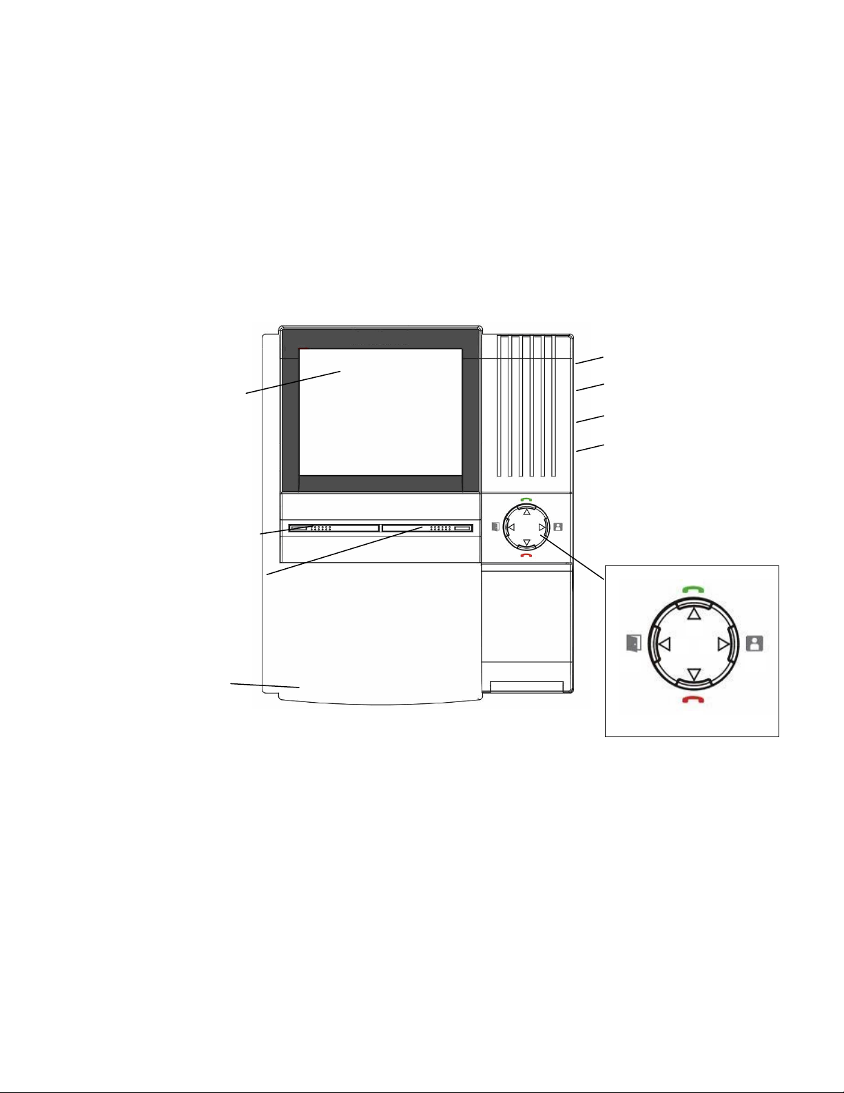
3.1 The Monitor Station
The Monitor Station comprises functional buttons, controls and a B&W screen.
6
1
3
4
5
7
8
9
B4
Figure 1: The Monitor Station
The following buttons, controls and screen display are located on your Monitor
Station:
2
B2
L3
B1
B3
1 4” B/W flat type CRT screen: Displays image delivered from the door
camera
2 Function button for Monitor/ Intercom/ Door Open and Cut off, see Figure
1, and refer to the chart on the next page for further descriptions.
Page 8 of 31 VI350-MANUAL-EN.R1.doc
Page 9
LED Light Button Name Press This Button To
ON while the
monitor
L1
displays video
B1
Monitor
Manually monitor camera
locations (press multiple times
to navigate between camera
locations)
Call other monitoring station for
ON while the
intercom is
L2
activated
B2
Intercom
intercom function between
monitors (additional monitors
required). Intercom time is 90
seconds before cut-off (10 sec
if no response)
ON while the
system has
L3
power
B4
Door Open
Release door strike (open door
- accessory door strike
required). If the monitor is not
online, this button has no effect
End function. If the monitor is
B3
Cut Off
not online this button has no
effect
3 Speak-out button (one way): While this button is pressed, you can talk
and the visitor can only listen in at the camera location
4 Speakerphone button (two way): When this button is pressed it allows for
two way conversation between the monitor and the camera unit.
5 Microphone: Picks up sound around the monitor.
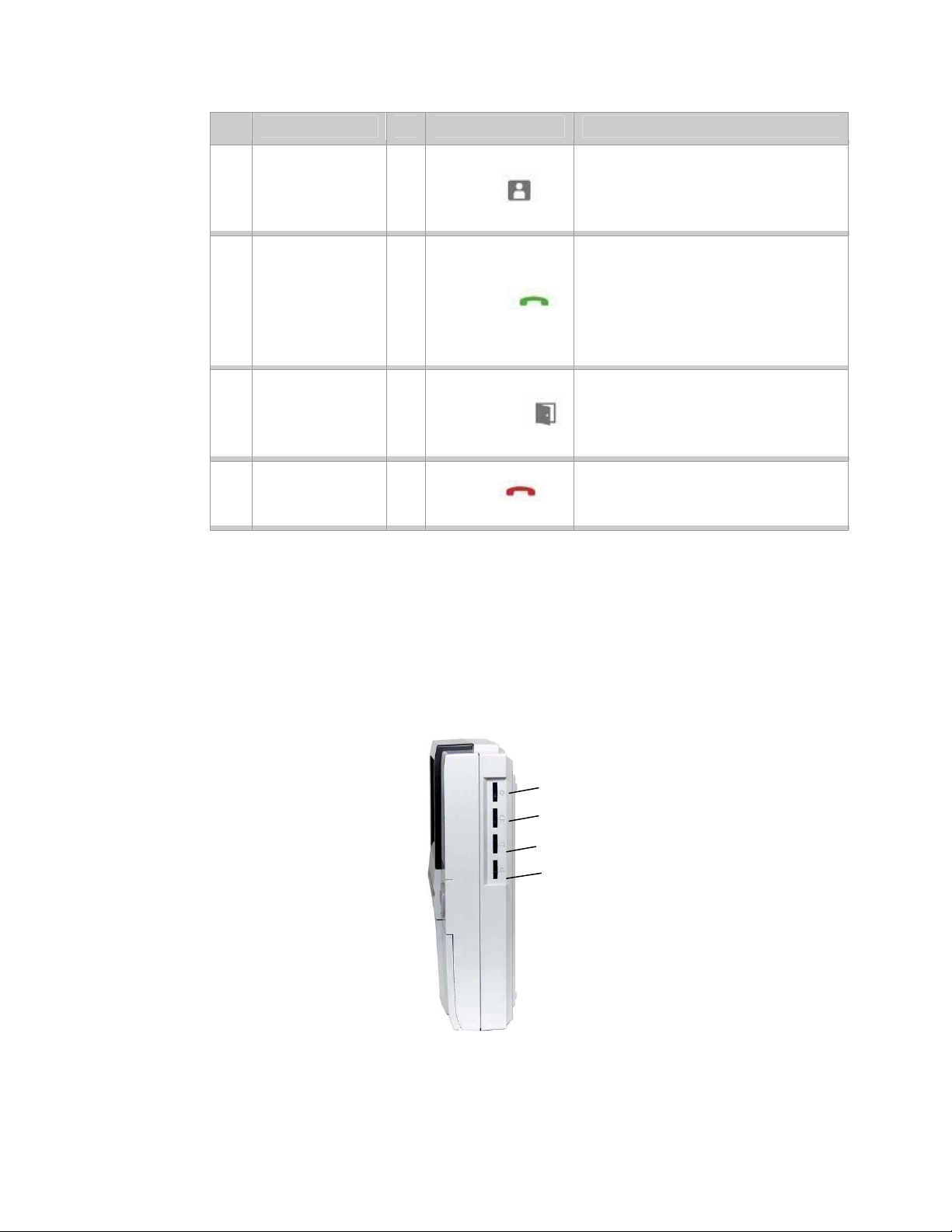
6
7
8
9
Figure 2: Monitor Side
6 Brightness control: Allows you to control the brightness of the picture.
Page 9 of 31 VI350-MANUAL-EN.R1.doc
Page 10
7 Sharpness control: Allows you to control the sharpness of the picture
8 Bell volume control: Allows you to adjust the bell volume on the monitor
9 Speakerphone volume control: Allows you to adjust the the volume for
two way conversation
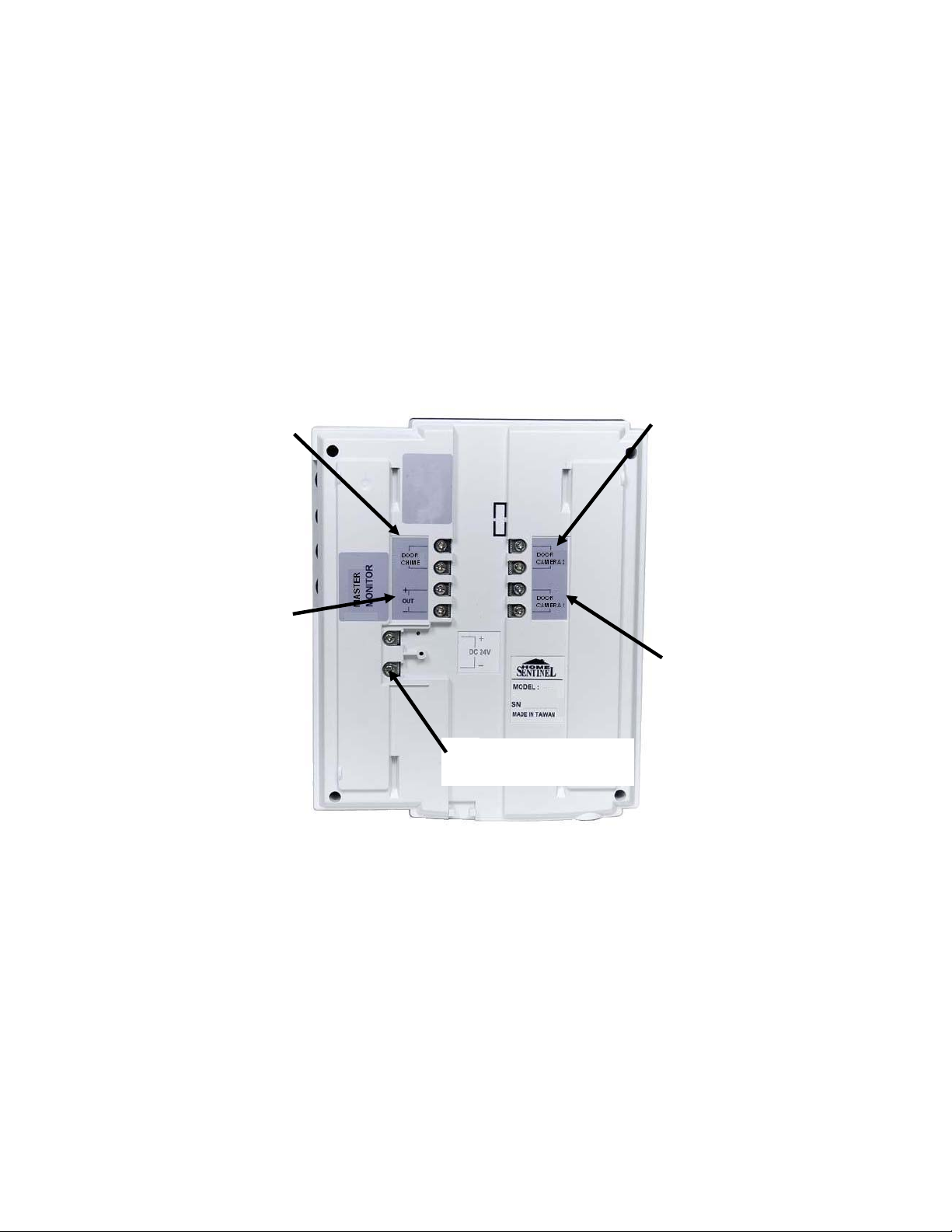
3.2 Monitor Terminal Connections
The Monitor Station terminal connections are located on the back of the Monitor and
are labelled for proper identification, see Figure 3.
4
DOOR CHIME
5
OUT
1
POWER ADAPTER
CONNECTION
Figure 3: Monitor Terminal Connections
3
DOOR CAMERA 2
2
DOOR CAMERA 1
The Monitor Station connections are labelled: Power Adapter, Door Camera 1, Door
Camera 2, Door Chime and Out, which are connected or used as follows:
1 Power Adapter Connection
(1) Remove the screw and the plastic cover
(2) Connect the 24V DC power adapter from the back of the monitor to
a wall outlet. Use the supplied adapter.
NOTE The terminal connection at the monitor is a Y-terminal.
Page 10 of 31 VI350-MANUAL-EN.R1.doc
Page 11

(3) Insert the +/- leads and screw them into the corresponding contacts
(refer to the DC 24V illustration).
2 Door Camera 1
(1) Connect the 2 conductor 18 gauge wire (20 meter/65 feet) from the
terminals marked, “Door Camera 1” on the monitor to the terminals
on the outdoor camera unit, marked, “Monitor”. Alternatively, you
can use your existing doorbell wiring (Please refer to APPENDIX 2,
page 29, for more details regarding this option).
3 Door Camera 2
(1) Connect two wires from this terminal to an additional door camera.
(Additional camera CA350 sold separately)
NOTE The connection between the camera and monitor has no polarity (the leads are
interchangeable, with no +/-).
4 Door Chime
Used to connect to an alternate door chime (optional).The terminal will activate
when the call button on the outdoor camera is pressed (active duration time
about 3 seconds)
NOTE This terminal is N.O. (normally open) dry contact.
(1) Connect an existing or additional door chime to this terminal
(optional).
5 Out
(1) Connect an additional slave monitor to the out terminal (additional
monitor M0350 sold separately).
NOTE This terminal has a polarity. Make sure to connect the out terminal correctly.
Page 11 of 31 VI350-MANUAL-EN.R1.doc
Page 12

3.3 The Doorphone Camera
The doorphone camera identifies and commnunicates with callers at the door.
3
2
1
4
5
6
Figure 4: The Doorphone Camera
The following functional controls and B&W camera are located on your doorphone
camera:
1 1/3” B/W CCD camera
A discreet high resolution black & white 1/3” CCD camera is located behind the
tinted cover.
2 Infrared Emitters
Infrared Light Emitting Diodes (LED) will give you clear pictures at night at
close range.
3 Microphone
Picks up sound around the camera.
4 Back-lit, Call button
Press this button to ring the doorbell chime and activate the monitor. The light
around the call button will illuminate when the system has power.
Page 12 of 31 VI350-MANUAL-EN.R1.doc
Page 13

5 Speaker
Emits sound from the monitor location.
6 Screw cover
This cover hides the screw that fastens the camera to the bracket.
3.4 Camera Terminal Connections
The Camera terminal connections are located on the back of the Camera and are
labelled for proper identification, see Figure 5.
2
1
3
Figure 5: Camera Terminal Connections
The Camera terminal connections are labelled:Door Release, Door Release Switch
and Monitor which are connected or used as follows:
1 Door Release
Connect this terminal to the Electric Door strike (optional).
NOTE For connecting an Electric Door strike see APPENDIX #1, page 27.
Page 13 of 31 VI350-MANUAL-EN.R1.doc
Page 14

2 Door Release Switch
The switch sets a door release terminal output type (N.O. dry contact or 12V
DC, 300 mA power output).
NOTE Please see The Door Release Function, page 23 for further information on how to
set this switch.
3 Monitor
Connect two wires from this terminal to the monitor’s Door Camera 1 input.
Page 14 of 31 VI350-MANUAL-EN.R1.doc
Page 15

4 Installation
This section describes the installation and setup of the video doorphone system.
The system monitor and camera are installed and then connected before utilizing
the functions.
IMPORTANT NOTE
Turn off the power to all units being used before connecting
or disconnecting cables.
Figure 6: Install Monitor and Camera
Install the video doorphone monitor and camera:
1 Monitor Installation
(1) Choose a suitable location in your home.
(2) Fasten the wall mount plate on the wall. Use the provided hardware.
Page 15 of 31 VI350-MANUAL-EN.R1.doc
Page 16

2 Camera Installation
(1) Fasten the wall mount bracket (for the camera beside your door) at
a height of between 60” – 64” from the ground.
NOTE When the camera is installed the lens of the camera is situated at the eye level of
the visitor
3 Connect the Camera to the Monitor
(1) Run the 20m/65ft cable from the camera unit to the monitor.
(2) Connect the two wires on the Monitor input marked “Door Camera”
NOTE It is a good idea to check all units together on a table/ bench prior to installing the
units in their permanent locations. However, audio feedback may occur if the
camera and monitor are set up beside each other.
4.1 Additional Door Camera Set-up
NOTE Additional CA350 camera is sold separately.
To enable a second camera:
(1) Press and hold the “Speakerphone (button #4) and Monitor- button
B1 per Figure 1 diagram” buttons at the same time while plugging in
the power supply.
(2) The additional Door Camera will enable when the monitor produces
a “Ding Dong” sound. Wait for 1.5 ~ 3 seconds for this “Ding Dong”
sound.
NOTE To toggle the additional camera ON/OFF disconnect and reconnect the power
supply while holding the “Speakerphone and Monitor” buttons at the same time
for 1~3 seconds, each time.
4.2 Video Doorphone Operation
Operating the doorphone system consists of responding to visitor calls from the
camera unit, monitoring audio and visuals, speaking to another monitor and
remotely opening the door.
1 Visitor Calls From Camera Unit
Page 16 of 31 VI350-MANUAL-EN.R1.doc
Page 17

• When the Call button on the camera is pressed, All monitors in the
system will ring the doorbell chime and turn the screen ON.
• After the call, if the “Speak-out” or “Two-way” button is not pressed, it will
cutoff after 30 seconds.
• If the “Speak-out” or “Two-way” button is pressed you have 90 seconds
to communicate before it automatically cuts off, or press the “Cut off”
button to terminate a call at any time.
2 Audio & Video Monitoring
• Press the Monitor button for monitoring a camera manually
• Press button again to switch the monitoring channel (If there is more
than one camera connected)
• Press the “Cut off” button to end the monitoring mode
3 Intercom Function between Monitors
• Press the “Intercom” button from any monitor to generate a call
signal at all monitor locations (i.e. expansion monitor)
• From another monitor respond to a call signal by pressing the “Two way”
button. The calling monitor and responding monitor can then engage in
the voice intercom function. The intercom LED will turn ON at all monitor
locations to indicate the intercom function is engaged.
NOTE Only 2 monitors are allowed in this function.
Now 2 monitors can talk to each other, “hands-free”. This function will
be terminated automatically after 90 sec, or when the “cut off” button is
pressed, or when the calling button on the outdoor camera is pressed.
4 Door Release Function
• Pressing the “Door Open” button at the monitor (which must be
online), will activate the door strike at the online camera. (Door strike
EDS350 sold separately).
• The “Door Open” button at an offline monitor cannot activate this
function.
Page 17 of 31 VI350-MANUAL-EN.R1.doc
Page 18

5 Video Doorphone Expansion Options
The video doorphone system can be expanded to add another monitor (MO 350)
and outdoor camera (CA 350), see Figure 7.
NEXT SLAVE
MONITOR
OUT
EXPANSION
MONITOR
IN
MASTER
MONITOR
Figure 7: Expansion Options — Monitor and Outdoor Camera
OUTDOOR
CAMERA
OUTDOOR
CAMERA
Page 18 of 31 VI350-MANUAL-EN.R1.doc
Page 19

5.1 The MO 350 Monitor
The MO 350 comprises functional buttons, controls and a B&W screen.
6
1 7
8
9
2
3
4
B4
B2
L3
L2
L1
B1
5
The MO 350 Monitor Controls:
1 4” B/W flat type CRT screen: Displays image delivered from the door
camera
2 Function button for “Monitor/ Intercom/ Door open and Cut off.”
B3
Figure 8: MO 350 Monitor Controls
Page 19 of 31 VI350-MANUAL-EN.R1.doc
Page 20

LED Light Button Name Press This Button To
ON while the
monitor
L1
displays video
B1
Monitor
Manually monitor camera
locations (press multiple times
to navigate between camera
locations)
Call other monitoring station for
ON while the
intercom is
L2
activated
B2
Intercom
intercom function between
monitors (additional monitors
required). Intercom time is 90
seconds before cut-off (10 sec
if no response)
ON while the
system has
L3
power
B4
Door Open
Release door strike (open door
– accessory door strike
required). If the monitor is not
online, this button has no effect
End function. If the monitor is
B3
Cut Off
not online this button has no
effect
3 Speak-out button (one way): While this button is pressed, you can talk
and the visitor can only listen in at the camera location
4 Speakerphone button (two way): When this button is pressed it allows for
two way conversation between the monitor and the camera unit.
5 Microphone: Picks up sound around the monitor.
6 Brightness control: Allows you to control the brightness of the picture.
7 Sharpness control: Allows you to control the sharpness of the picture.
8 Bell volume control: Allows you to adjust the bell volume on the monitor.
9 Speakerphone volume control: Allows you to adjust the the volume for
two way conversation.
Page 20 of 31 VI350-MANUAL-EN.R1.doc
Page 21

4
RESERVE
5
OUT
1
POWER ADAPTER
CONNECTION
3
RESERVE
2
IN
Figure 9: The MO 350 Terminal Connection
1 Power Adapter Connection: Remove the screw and the plastic cover to
connect the 24V DC power adapter from the back of the monitor to a wall
outlet using the supplied adapter. The terminal connection at the monitor
is a Y-terminal, and the +/- leads need to be inserted and screwed into the
corresponding contacts, see Figure 9.
2 IN+ /- : This terminal is used for connection to main/other slave monitor
OUT+ / - terminal.
NOTE Make sure to connect IN + to OUT + and the IN - to OUT -. This terminal has a
polarity.
3 OUT+ / - : This terminal is used for connection to other slave monitor “IN+
/-“ terminal.
NOTE Make sure to connect OUT + to IN + and the OUT - to IN -. This terminal has a
polarity.
Page 21 of 31 VI350-MANUAL-EN.R1.doc
Page 22

5.1.1 MO 350 Monitor Installation
1 Connect 2 wires IN+ and IN- on the back of the expansion monitor MO350
to the OUT+ and OUT- on the master monitor or other expansion monitor
(MO 350)
NOTE When connecting multiple monitors, connect all monitors in series from the
master monitor.
5.1.2 MO 350 Monitor Operation
1 Visitor Calls From Camera Unit
• Operates the same as the main monitor unit
• When the monitor LED is on it indicates the other monitor unit is on line
to the camera unit
• When a visitor calls, you can answer from any monitor unit which will
automatically cut-off all the other monitor stations.
• When the other monitor unit is online with the camera unit, you cannot
access the system.
2 Audio & Video Monitoring
• Operates the same as the main monitor unit
• If other monitor is online, it cannot access the system.
3 Intercom between Monitoring Units
• Operates the same as the master monitor unit
4 Door Release Function
• Operates the same as the master monitor unit
Page 22 of 31 VI350-MANUAL-EN.R1.doc
Page 23

5.2 The CA 350 Outdoor Camera
CA 350
INSTALLATION
2 WIRES TO LOCK DOOR
RELEASE CONTROL
(IGNORE WHEN NO DOOR
STRIKE IS CONNECTED)
Figure 10: Connect CA 350 Outdoor Camera
2 WIRES TO
‘DOOR CAMERA 2’
TERMINALS OF
THE MAIN
MONITOR
5.2.1 CA 350 Outdoor Camera Installation
See Figure 7, page 18 for diagrams of the terminal connections.
1 Connect the two wires from the “Monitor” terminal on the camera to the 2
terminals on the main monitor, marked Door Camera 2.
2 Press and hold the “Speakerphone and Monitor” buttons (B1+4 from
Figure 1 diagram) together at the main monitor for 1~3 seconds while
plugging in the power supply. You will hear the “ding dong” sound from
the monitor to confirm the addition door camera is set up.
5.2.2 CA 350 Outdoor Camera Operation
1 This CA 350 operates the same as the main camera unit.
5.2.3 The Door Release Function
The CA 350 Outdoor Camera includes selectable door release outputs, either a
normally open (N.O.) dry contact or 12V DC, 300 mA using the switch setting.
NOTE For information on connecting an electric door strike (i.e. magnetic lock), see
APPENDIX #1, page 27.
Page 23 of 31 VI350-MANUAL-EN.R1.doc
Page 24

The DOOR RELEASE switch
provides a normally open
contact with no polarity
allowing maximum by-pass
current of DC 24V or AC 24V
1A
Left Side:
N.O. Dry Contact
The DOOR RELEASE switch
provide current output of
maximum 12V DC 300 mA
Right Side:
12V DC 300mA
Figure 11: Switch Setting
Page 24 of 31 VI350-MANUAL-EN.R1.doc
Page 25

6 Troubleshooting Guide
Before requesting service, check the troubleshooting guide to solve the problem.
Problem Solution
No Power ( no picture on monitor) Make sure that the AC plug is firmly
inserted into the AC outlet. Make sure
that the DC Power is firmly connected to
the monitor with correct polarity (+/-).
System is on, but no picture on the
monitor
Sound is too low Adjust the volume control clockwise
The picture is too dark or too white Adjust the brightness and sharpness
Audio won’t work correctly after
adjusting the volume
NOTE Be sure to use the Power Adaptor supplied with the system.
Make sure that the cable is firmly
connected between the monitor and the
camera. Adjust the brightness and
sharpness controls clockwise
controls
The system may have been
inadvertently set to Demo mode. Press
and hold Speakerphone and Intercom
buttons for 1~3 seconds while plugging
in the power supply. Listen for noise to
indicate toggling of the Normal/Demo
modes.
Page 25 of 31 VI350-MANUAL-EN.R1.doc
Page 26

7 Specifications
Monitor Unit
Power Source: Full range switching power
Power Consumption: Active 15W, standby 3W
CRT Screen: 4" B/W Flat type
TV system: B/W EIA
Resolution: Over 380 TV Lines
Conversation Time: 90 seconds
Conversation System: Hand Free Semi Duplex
Multi-Voltage 100 ~ 240Vac
DC 23V, 0.75A
Max. Wiring Distance
(Terminal to Terminal):
Operating Temperature:
Dimensions: 6.69" (W) x 8.18" (H) x 2.13" (D)
Camera Unit
Power Source: supply from monitor
Resolution: 380 Lines
Image Sensor: 1/3" B/W CCD
TV System: B/W EIA
Illumination: Infrared LED
Min.Intensity of Illumination: 0 Lux (up to 3 feet from camera)
Operating Temperature:
Lens:
Dimensions: 3.94" (W) x 5.24" (H) x 1.38" (D)
60 M with AWG #20 wire
100 M with AWG #18 wire
32°F ~ 104°F (0 ~ 40°C)
-13°F ~ 122°F (-25°C ~ 50°C)
3.7 mm F2.0, 90° diagonal viewing
Page 26 of 31 VI350-MANUAL-EN.R1.doc
Page 27

8 APPENDIX #1
8.1 Connect Electric Door Strike or Magnetic Lock (optional)
IMPORTANT NOTE
Before attempting to install the Electric Door Strike or
Magnetic Lock please call a professional such as a locksmith
or electrician to help with your installation.
1. N.O. Dry Contact Option
You can open the door remotely by pressing the Door Open button on the monitor to
release an electric door strike or magnetic lock
(1) Connect two wires (18 gauge)
to the Outdoor Camera marked
“Door Release” to the Electric
Door Strike.
(2) One wire from the Outdoor
Camera will connect to the
positive terminal on the power
supply.
(3) The other wire from the
Outdoor Camera will connect to
the positive terminal on the door
strike unit.
(4) A third wire will connect from
the negative terminal on the
power supply to the negative
terminal on the door strike unit.
Page 27 of 31 VI350-MANUAL-EN.R1.doc
Page 28

IMPORTANT NOTE
You will need to install a power supply that is compatible with
the eletronic door strike installed.
For example: if a 12V DC / 320 mA Electronic Door Strike is
used, then a compatible power supply would be 12V DC / 500
mA (the power supply should have a higher current rating
than the door strike so that it could handle the requirement
CAUTION
Potential for damage to the unit
Do not overload the current on the lock.
Current overload may cause damage on the monitor and
door strike unit
2. 12V DC 300 mA Power Option
Connect two wires (18 gauge) between the camera terminal marked “Door Release”
and the Electronic Door strike, see Figure 12.
Figure 12: 12V DC 300 mA Power Option
NOTE When using the 12V DC 300 mA power option, make sure that the Electric Door
strike used is rated for 12V DC and the current rating less than 300mA.
Page 28 of 31 VI350-MANUAL-EN.R1.doc
Page 29

9 APPENDIX 2
9.1 Connect the Video Doorphone System with Existing Wiring
Although there are many different styles of doorbell systems on the market, they mainly
consist of the same 3 main components and are installed in the same way.
These are the 3 main components in a typical doorbell system: Doorbell (a visitor at the
door presses it), Transformer (or power –it is attached to the house circuit and provides a
voltage output of approximately 6 to 24 volts) and Doorchime (it rings when the doorbell is
pressed).
Doorbell
/Doorchime wire
Doorbell
Button
Doorbell/
Transformer
wire
Transformer
lowers voltage
Doorchime
Transformer/
Doorchime wire
Household circuit
wires
Figure 13: Household Wiring for a Typical Doorbell
The following basic instructions explains how to install the Video Doorphone System
using your existing doorbell wiring.
IMPORTANT NOTE
Turn off the breaker that supplies power to the doorbell
before attempting to install the doorphone system. Please
call a professional such as a locksmith or electrician to help
with your installation.
Step 1. Remove the Doorbell Wires from the House Circuit
NOTE Typically Doorbells use "transformers" to convert the current in your house to low voltage current
(i.e. approximately 6 to 24 volts). The transformer is attached to the house circuit and provides
power to the Doorbell.
Page 29 of 31 VI350-MANUAL-EN.R1.doc
Page 30

2. Disconnect the Doorbell/ Transformer wire (wire attached to the
Transformer which leads from the Doorbell, see Household Wiring for a
Typical Doorbell).
3. Disconnect the Transformer/ Doorchime wire (wire attached to the
Transformer that leads from the Door Chime, see Household Wiring for a
Typical Doorbell).
4. Join the two disconnected wires (Doorbell/ Transformer wire and
Transformer/ Doorchime wire) with wire connectors.
Step 2. Remove the Doorbell and Connect the Door Camera
1. Uninstall the Doorbell cover.
2. Disconnect the wires from the Doorbell’s terminal screws.
3 Remove the Doorbell.
4. Connect the existing Doorbell wires to the terminals marked Monitor
at the back of the Door Camera.
5. Mount the Doorphone Camera (refer to the Installation chapter for
instructions).
NOTE The Doorphone Camera should be located at visitor height for viewing.
Step 3. Remove the Door Chime and Connect the Monitor
1. Uninstall the Door Chime cover.
2. Disconnect the wires from the Door Chime’s terminal screws.
3 Remove the Door Chime.
4. Connect the existing doorbell wires to the terminals marked CAM1 at
the back of the Monitor.
NOTE If the existing wires are not long enough for you to locate the Monitor then you must extend the
wires to the location of the Monitor.
5. Mount the Monitor (refer to Installation chapter for instructions).
Page 30 of 31 VI350-MANUAL-EN.R1.doc
Page 31

It’s all on the web
Product Information
User Manuals
Quick Start Guides
Specification Sheets
Software Upgrades
Firmware Upgrades
VISIT
www.homesentinel.com
www.homesentinel.com
Lorex Technology Inc
 Loading...