

Sentinel Leak Defense System Installation Manual & Owner's Manual
Installation Guide
& Owner’s Manual
Indoor installation only
CRITICAL NOTES
for installing the
Leak Defense System
are highlighted in shaded boxes
throughout the document.
It is essential these
critical notes are read
prior to installation.
VERY IMPORTANT!
The Leak Defense System large
valve/flowbody assemblies can
weigh over 15 lbs. Bracing may be
required if your plumbing system
is unable to support this weight.
Please leave this guide with the homeowner when installation is complete.
INSTALLER:

Congratulations on installing the most advanced system available to protect
Homeowners against catastrophic loss due to water damage.
The Leak Defense System monitors the flow of water into your home 24 hours a day, 7 days a week. Should
a leak develop, the system will alarm, and, if the leak is not corrected, will automatically halt all water flow to the home before
additional damage can occur.
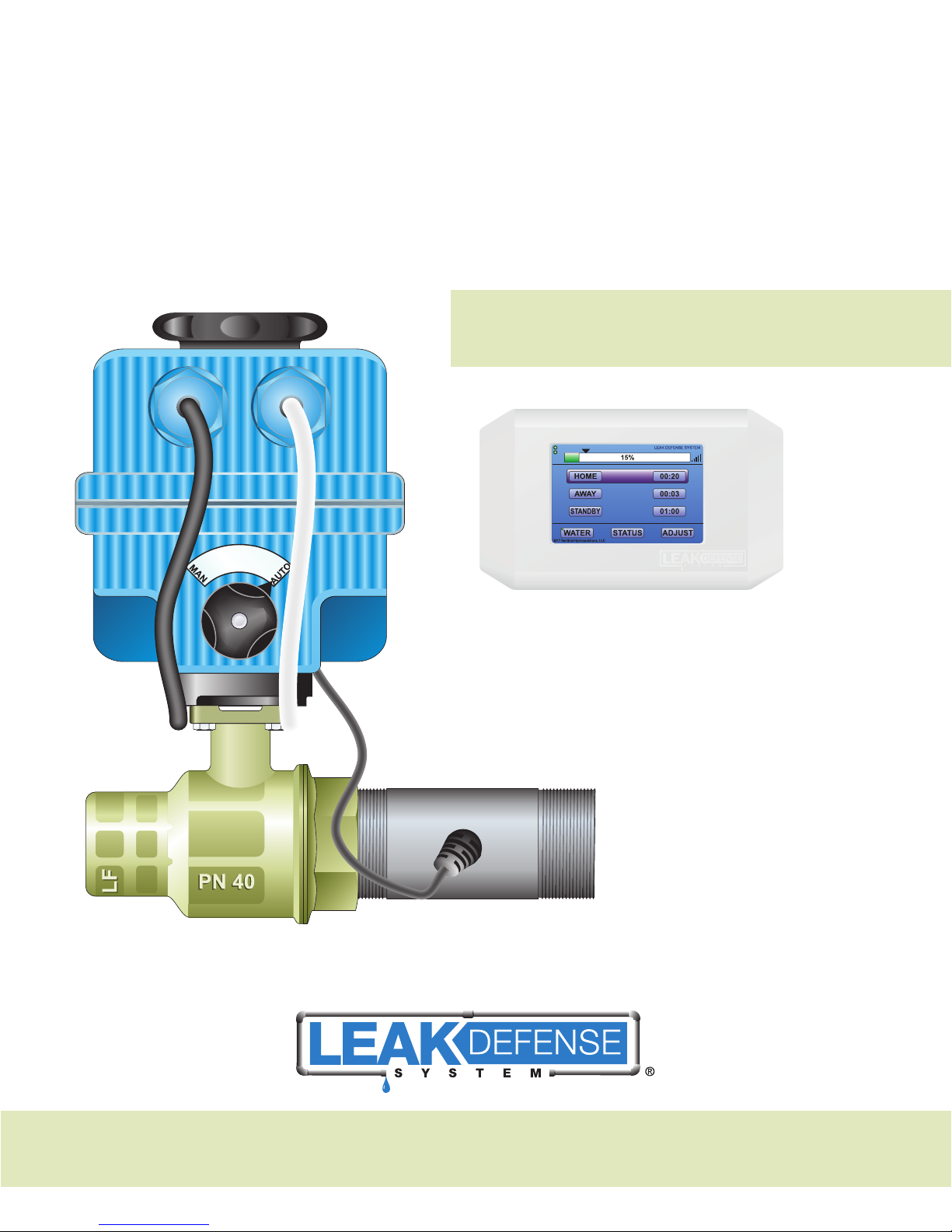
System Overview
The system includes a motorized ball valve, extremely low flow sensors and a control panel with a touch screen display.
If water flow to your home continuously exceeds your system settings for more than your predetermined time, the alarm will
sound and the ball valve will close — shutting off water to your home and potentially preventing major water damage. So the
principle of the system is continuous water flow over time. Everything in your house allows for water to start and stop. A leak
is the one situation where the water does not stop. The Leak Defense System is looking for this.
System Features
• Constant monitoring of your water system (24 hours per day, 7 days a week )
• Leak detection with audio/visual alarm notifications
• Automatic water shut-off protection to minimize water damage
• State of the art wireless color touch screen control panel
• System retains all settings in memory, even if the electrical power is interrupted
• Simple menu driven programming
• Ability to turn water ON and OFF from the control panel
Serial Number:
Installation Date:
Company / Person who installed
the Leak Defense System:
Installer Phone Number:
Sentinel Hydrosolutions Leak Defense System
Help Line: 1.866.410.1134
(9:00 am to 4:00pm Pacific Time)
LEAK DEFENSE INSTALLATION GUIDE 2

INSTALLER —
After installation, review Leak Defense System operation with the owner
Using pages 21- 23 of the Owner’s Manual section as a guide:
a. Explain the system and use the control panel to demonstrate the various Leak Defense System functions.
b. Encourage the owner to physically interact with the control panel during your demonstration. This will promote a level
of comfort and usability.
c. Clearly explain the purpose of the Leak Defense System is to detect and protect from leaks and not to
locate the source of leaks.
d. Explain the Leak Defense System will constantly monitor water flow every day.
e. Explain the importance of using the AWAY mode
1. Explain the difference between the HOME and AWAY mode settings
2. Explain that not using the AWAY mode when the home is unoccupied limits protection to the HOME mode settings.
NOTE: Take the owner through an alarm scenario as part of the customer education and to test the alarm.
OWNERS —
There are helpful videos on our website with information that might be more up to date regarding the operation of your
Leak Defense System. You can access them at www.leakdefensesystem.com
LEAK DEFENSE INSTALLATION GUIDE 3
Table of Contents
INSTALLATION GUIDE:
Planning and System Preparation
Step 1: Tools and supplies needed ................................................................. 6
Step 2: Pre-Installation survey ....................................................................... 6
Installing the Valve/Flowbody
Step 3: Determining the valve location for the Leak Defense System ..................... 7
Power & Panel Location
Step 4: Locate an electrical outlet for the valve ................................................. 8
Step 5: Determine wireless control panel location .............................................. 8
Figure 1: Piping Diagram ............................................................................... 9
Installing the Valve/Flowbody
Step 6: Cut a space to accommodate valve/flowbody ...................................... 10
Step 7: Install Leak Defense System valve/flowbody ........................................ 10
Checks & Programming
Step 8: Connecting to power ...................................................................... 11
Step 9: Mount the wireless control panel ....................................................... 11
Step 10: Power the system .......................................................................... 11
PAGE
The Wireless Control Panel
Step 11: Confirm control panel water shut-off feature ......................................... 12
Step 12: Calibrating the system ................................................................... 13
Step 13: Verify and set automatic shut-off features .......................................... 14
Step 14: Other Features / Selecting the mode ................................................ 15
API-Alarm
Step 15: API-Alarm Panel Interface ................................................................ 16
API
Connecting an Intermatic Spring Wound Timer ................................................ 18
Wiring a PAM Relay ................................................................................... 18
Wiring a Hardwired Water Recirculation Pump ................................................. 19
Connnecting a POLD to Your LDS-3 System ............................................... 19-20
OWNER’S MANUAL:
Control Panel Overview ............................................................................... 21
Setting HOME and AWAY / Turning off the water / Program the system ................ 22
Partial flow feature ..................................................................................... 23
Alarm is sounding. What do I do? ................................................................. 23
Set up wifi and web-based app .................................................................... 24
Fine-tuning to your lifestyle .......................................................................... 25
Warranty
Leak Defense System Limited Warranty .......................................................... 26
LEAK DEFENSE INSTALLATION GUIDE 4

Installation Guide

Planning & System Preparation
STEP 1:
Tools and supplies needed
a. Pipe cutting, soldering equipment and supplies
b. Tape measure
c. Pipe marking pen
d. #2 Phillips screw driver
e. 1⁄4” twist drill bit and drill (diameter of no more than .160” )
f. 2 ea. - #6 drywall anchors and screws
STEP 2:
Pre-Installation Survey
There are six steps necessary to properly perform a pre-installation survey. These are:
1) Determine the best location for the Leak Defense System valve.
The valve must be located downstream of any fire sprinkler system and, ideally, should be located down-stream of
all irrigation lines. The valve should be installed in an indoor location free from direct sun and moisture.
2) Determine if any of the following water using systems is downstream of the Leak Defense System valve:
a) Reverse Osmosis Water Purification System d) Automatic Pool Fill System
b) Water Softener System e) Outside hose bibs
c) Irrigation System f) Any other appliance that may automatically use water
3) If any of the above is present down-stream of the Leak Defense System valve, please refer to the document,
LDS-API, Alarm Panel Interface.
4) Determine where a non-switched 120 VAC outlet is in a dry location and determine how you will get the
(2 conductor) power wire to the transformer at this location.
24 VAC from the transformer should not be run longer than 100 feet. If a longer power wire is needed, it is
recommended that a new 120VAC outlet be installed closer to the Leak Defense System.
5) Determine where the customer would like the wireless control panel and confirm it is within 100’ of
where the valve is installed.
A standard 110 outlet is required to provide power to the wireless panel.
6) A battery backup or generator is recommended for locations that are prone to power outages.
LEAK DEFENSE INSTALLATION GUIDE 6

STEP 3:
Valve Location
Determining the valve location for the
The Leak Defense System valve must be installed on the main water line and downstream of the primary shut-off valve,
pressure regulator, irrigation line and fire sprinkler line. (See Figure 1 on page 9.)
Typical location of the Leak Defense System valve installation will be in a garage, basement or crawl space. If the home is
on a concrete slab, the valve can be installed in the garage or before water enters the home. In the latter case, the valve
should be located at least 18” above grade. It must be protected from direct sun exposure, moisture and
freezing conditions.
Leak Defense System
Other important considerations include:
a. Install the valve in an accessible location allowing easy access for proper installation and maintenance.
b. Some water utilities require the valve be a minimum of 18” downstream of the water utility meter.
c. If possible, install the valve downstream of a manual shut-off valve to allow for easier maintenance.
d. A bypass around the valve is not required but may be recommended.
IMPORTANT: The valve cannot be installed where it may be submerged in water or exposed to moisture or freezing
conditions. An appropriate insulated or water proof box should be installed to protect the Leak Defense System.
Note: If there is a fire sprinkler and/or irrigation system that branches off the building supply downstream of the utility
meter, the Leak Defense System valve must be installed on the building supply downstream of the fire sprinkler, and
if possible, irrigation supply branch. In no instance may the Leak Defense System be installed in a way that it will
interfere with the fire sprinkler system.
Note: The Leak Defense System sees water flowing, but does not differentiate between flow direction (flow in vs. out).
As water main pressures fluctuate, there may be a slight flow out of the home/office which will be seen as flow.
A backflow preventer valve (=SPRING check valve) may be considered to remedy this. This backflow will usually only
be an intermittent or sporadic event, while a leak will have continuous water movement.
LEAK DEFENSE INSTALLATION GUIDE 7

Power & Panel Location
STEP 4:
Locate an electrical outlet for the valve
a. Locate an available 120 VAC outlet close to the valve into which the transformer can be plugged.
Make sure this outlet is not connected to an on/off switch or a GFI.
b. The 120 VAC outlet should not be more than 100 feet from the valve. If a longer power wire is needed,
it is recommended that a new 120 VAC outlet be installed closer to the valve.
Critical: The outlet must be located in a dry location.
STEP 5:
Determine wireless control panel location
a. The control panel should be located inside near the most frequently used door of the home or in an easily
accessible area.
b. Once a location is chosen, make sure there is an outlet within 6’ to provide power to the wireless panel.
c. The wireless control panel should be located no farther than 100 feet from the Leak Defense System valve.
d. An optional power supply is available upon request. The optional power supply allows the contractor to conceal the low
voltage wire behind drywall. The standard length is 10’ but additional wire may be requested.
Note: Please install control panel at least 8 inches (20 centimeters) from a common use area, per FCC/IC regulations.
LEAK DEFENSE INSTALLATION GUIDE 8

Figure 1
General Piping Diagram
LEAK DEFENSE INSTALLATION GUIDE 9
 Loading...