

Sentinel KalGuard Installation Manual

Page 1
KalGUARD
®
Installation Manual
Water Treatment Equipment to
Manage Hardwater Limescale
Version 3 – April 2018
IMPORTANT
Please leave a copy of this
manual with the KalGUARD
equipment in its plant room

Page 2 KalGUARD
®
Installation Manual V3 04/18
WARNING:
The KalGUARD Controller circuit boards
have live connections and should only
be accessed by a competent person.

Page 3 KalGUARD
®
Installation Manual V3 04/18
Index
Section Page
Installation Advice 4
System and Component Arrangement 4
Typical Installation 5
General Notes 6
Specification Tables 7
Component Checklist 8
Principle Installation Guidelines 9
Installation Schematics 10–12
Concluding the Installation 13
Pipework Sanitation 13
Preparing the KalGUARD for Commissioning 14
Technical Description: MK1 Controller 15–17
Technical Description: MK2 Controller 18–19
Water Meter 20
Water Filtration 21
Pulse Splitter User Instructions 22–23
Health & Safety 24
Servicing & Monitoring 25
Service Contract 25
Recommended Monitoring 25
Other Service Considerations 25
Automatic Servicing 25
Commissioning Details 26
Trouble Shooting 27–28
Service Log 29–31
Please copy page 31 if additional sheets are needed
Please visit www.sentinelprotects.com/uk/guarantee-registration
for Guarantee Registration and Terms and Conditions.
KalGUARD is a registered Trade Mark and is protected by
CTM 012658688 owned by Sentinel Performance Solutions Limited.
Page 4 KalGUARD
®
Installation Manual V3 04/18
Installation Advice
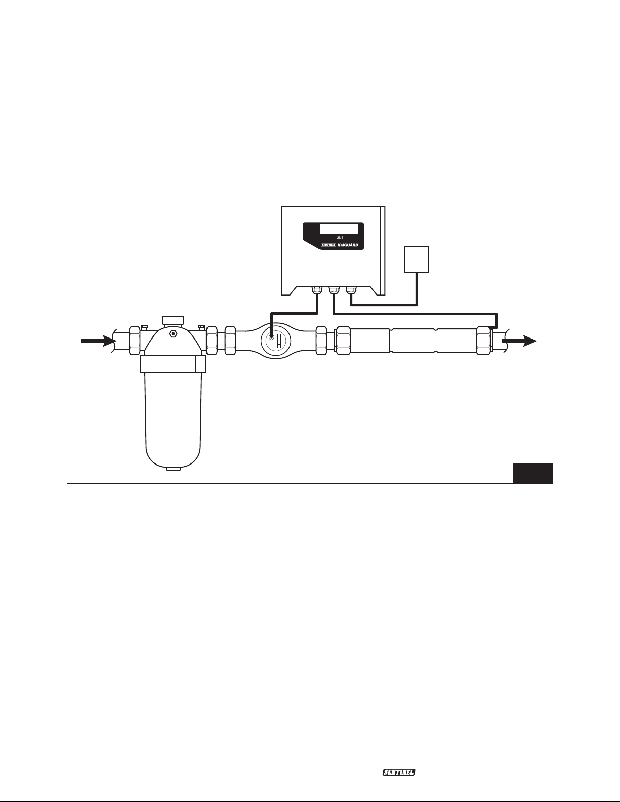
SYSTEM AND COMPONENT ARRANGEMENT
It is important to ensure that the KalGUARD system components are installed in the same
water flow line, as per Fig. 1. They should typically be arranged in a ‘side-stream loop’ to the
main water feed line. It should be possible to place the side-stream loop in or out of service by
the operation of isolation valves on the loop and a by-pass valve on the main water feed line.
KalGUARD Anode Unit
This component contains a zinc anode
which continuously doses small amounts of
zinc ions into the water passing through it to
inhibit scale formation.
KalGUARD Controller
The controller links with the water meter to
automatically match the output of zinc ions
to water flow.
25/55 µM Water Filter
Filtration of incoming mains water to
≤50µm is recommended to ensure
optimum performance of the equipment.
For all pipe sizes up to 108mm (4"), the filter
supplied will be a “stacked disc" type. The
filter must always be installed upstream of
the KalGUARD anode unit.
Water Meter
The water meter provides essential data
to the KalGUARD controller to ensure
intelligent activation of the KalGUARD anode
unit. It is NOT intended for direct paralleling
with a BMS for volumetric water coupling
(see later – “Installation of Electrics/
Electronics").
Following the completion of the
installation, please refer to the check list
on page 14 before contacting Sentinel on
01928 704 330 to arrange
COMMISSIONING.
Filter
Controller
Anode UnitWater
Meter
Mains System
Mains 240V/50Hz
(Single phase)
Fig. 1
Page 5 KalGUARD
®
Installation Manual V3 04/18
Installation Advice
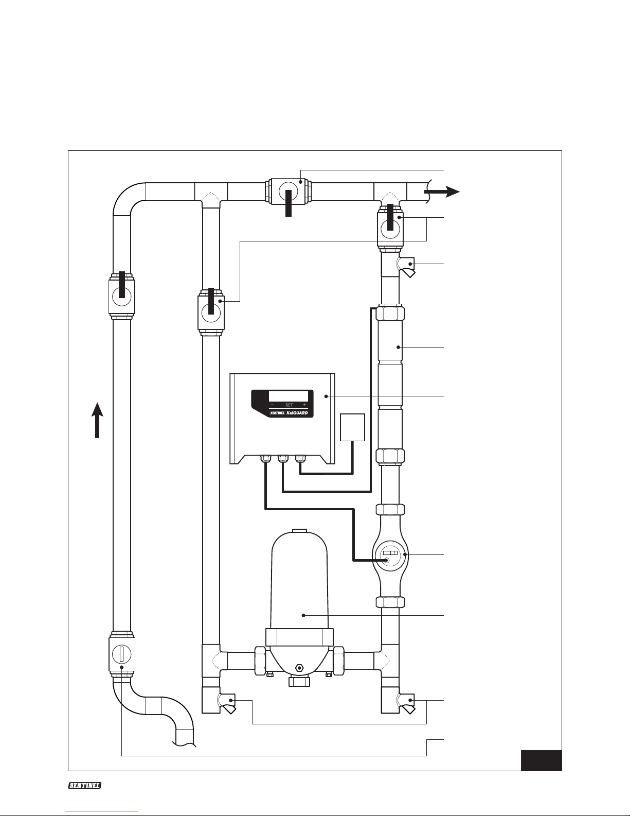
TYPICAL INSTALLATION
When installed, the KalGUARD ‘kit’ will have this general appearance.
By-pass Valve
Side-stream
Isolation Valves
Drain Valve
Anode Unit
Controller
Flow Meter
Filter 55µM
Drain Valves
Non-return
Valve
Fig. 2
Water Flow Direction
Earth Strapping Clip
Anode Unit Supply Cable
Power Cable

Page 6 KalGUARD
®
Installation Manual V3 04/18
Installation Advice
Note 4:
The combination of the water flow meter
and system controller provides intelligent
operation of the KalGUARD anode unit. This
reactive intelligence limits operation of the
KalGUARD system during periods when
there is low or no water flow and maximises
effective treatment at other times.
Note 5:
It is important that ALL INSTALLATIONS
HAVE EASY ACCESS FOR MAINTENANCE
PURPOSES.
Note 6:
The side-stream configuration allows the
maintenance engineer to divert the water
flow via the by-pass section during servicing
and thus ensure no interruption of the water
supply to the building. The only variation
that can apply is that the water flow meter
may instead be mounted in the adjacent
common pipework. Where the unit feeds
a cold water storage tank, the side-stream
configuration can sometimes be omitted.
This is only the case where the storage tank
will supply adequate water to allow servicing
to take place.
Note 7:
The KalGUARD anode unit is WRAS
approved and is safe to install in drinking
water pipework.
Note 8:
Only the water meter supplied by Sentinel
can be used with the KalGUARD system.
GENERAL NOTES
Note 1:
The following items are also required for
installation, but not provided with the
KalGUARD ‘kit’ depending on installation
configuration: (See fig 2 for reference)
• Delayed action inlet valve
Where the equipment is installed on a
water system feeding a preliminary break
tank of < 10m
3
(prior to a water system
booster set) the break tank inlet water
valve should be a “delayed action" type.
This is to ensure fast or full flow from the
mains when actuated.
• Non-return valve
• Quarter-turn isolating valves
Up to three required – refer to the
appropriate installation diagram.
• Drain valves
Up to four required – refer to the
appropriate installation diagram.
Note 2:
Lagging is recommended. All cold metal
pipework surfaces encourage condensation
which can be prevented by appropriate
fixed lagging. The KalGUARD anode unit
should have a removable insulating jacket
held closed by Velcro strips and its ends
closed with draw strings or tapes. A similar
arrangement will protect the flow sensor
water meter.
Note 3:
It is preferable to install the KalGUARD onto
the incoming mains water line for whole
water system protection. Where this is
not possible, it can be applied to just the
hot water system to protect commercial
and industrial water heaters. The intention
is also to maximise protection for the
downstream hot water pipework. This can
also become fouled in areas where water
supplies have high mineral content (‘hard’
water) and consequently high potential for
causing flow-restricting limescale deposits.

Page 7 KalGUARD
®
Installation Manual V3 04/18
Installation Advice
KALGUARD SPECIFICATION TABLE – ANODE UNITS
Product
Code
Length Diameter
(Main
Body)
Weight
(KG)
Design Flow
(l/m)
Design
Fl ow m³/ h
Connection ΔP (bar)
@ Design
Flow
KALG22 375 42 2.5 37 2.22 ¾" BSP Female 0.15
KALG28 450 54 3.1 64 3.84 1" BSP Female 0.13
KALG 35 484 67 4.6 96 5.76 1 ¼" BSP Female 0.23
KALG 42 505 67 4.9 142 8.52 1 ½" BSP Female 0.26
KALG 54 525 76 6.4 255 15.3 2" BSP Female 0.26
KALG 67 650 108 16.8 423 25.38 2 ½" 8 bolt DIN/ANSI Flange 0.20
KALG76 650 134 30.0 523 31.38 3" 8 bolt DIN/ANSI Flange 0.23
KALG108 650 160 3 7.0 1099 65.94 4" 8 bolt DIN/ANSI Flange 0.20
KALGUARD SPECIFICATION TABLE – CONTROLLERS
Version For Width
(mm)
Height
(mm)
Depth
(mm)
Display Display BMS Connectivity IP Rating
Mk 1 67, 76, 108mm KG 193 180 103 LCD 240 V ACFault Alert, Optional Pulse Splitter 65
Mk 2 22, 28, 35, 42 &
54mm KG
259 213 66 OLED 240 V ACFault Alert, Remote Switching (on/
off), Optional Pulse Splitter
65
KALGUARD SPECIFICATION TABLE – WATER METERS
KG Size Water
Meters
(in)
Length
(mm)
Width
(mm)
Height
(mm)
Weight
(KG)
Connections Qmax*
(m³/h)
Qn*
(m³/h)
Qmin
(l/h)
Max
Pres.
(bar)
K Value
(litre)
ΔP
(bar) @
Design
Flow
22 ¾" 190 99 107 1.7 ¾" BSP Male 5 2.5 50 16 1 0.20
28 1" 160–260 104 115 2.6 1" BSP Male 7 3.5 70 16 1 0.35
35 1 ¼" 160–260 104 120 3.1 1 ¼" BSP Male 12 6 100 16 1 0.38
42 1 ½" 200–300 125 14 8 5.2 1 ½" BSP Male 20 10 200 16 1 0.20
54 2" 300 125 173 8.5 2" BSP Male 30 15 450 16 1 0.23
67 2 ½" 200 65 200 10.1 PN16 Flanges 50 25 750 16 10 0.06
76 3" 200 80 270 13.8 PN16 Flanges 80 40 1200 16 10 0.03
108 4" 250 100 270 18.2 PN16 Flanges 120 60 1800 16 10 0.05
*Qmax = Max flow (short period)
*Qn = Nominal flow
KALGUARD SPECIFICATION TABLE – FILTERS
Connection
Size
For Length
(mm)
Width
(mm)
Height
(mm)
Weight
(KG)
Connection
Diameter (mm)
Average Flow
(m³/h) @ 55u
ΔP (bar) @
Design Flow
1" Short 22mm KG 158 130.0 233 1.1 25 3.15 0.11
1" Super 28mm KG 158 130.0 340 1.42 25 4.2 0.05
1 ½" Super 35mm KG 200 130.0 350 1.5 40 6.3 0.12
2" Leader 42 &
54mm KG
230 215.0 425 3.2 50 11 0.28
3" Leader 67m m KG 742 228.0 320 6.3 90 22 0.17
4" Leader 76mm KG 1188 319.0 445 28.8 110 42 0.05
6" Leader 108mm KG 1188 319.0 415 30.4 160 49 0.06
Page 8 KalGUARD
®
Installation Manual V3 04/18
Installation Advice
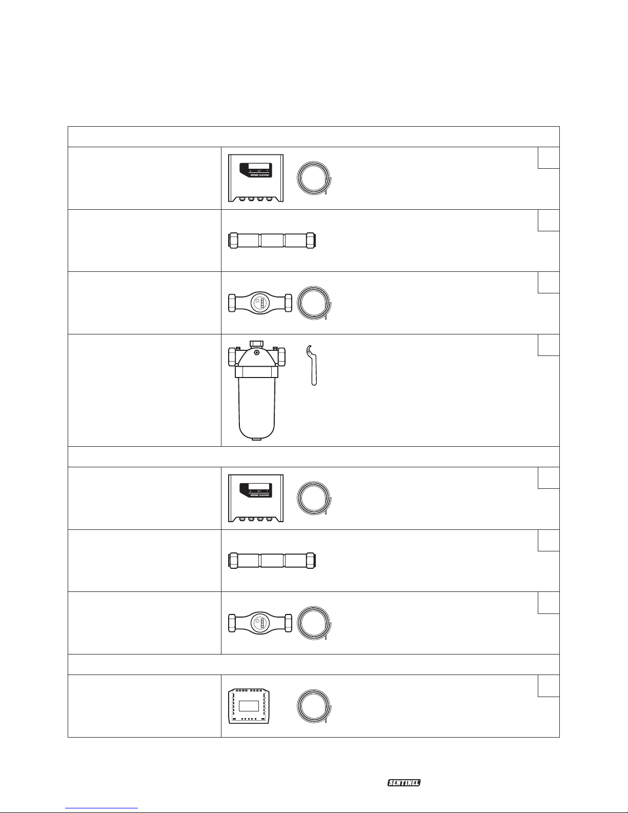
COMPONENT CHECKLIST
Full Pack
Controller with anode unit
supply cable
Anode Unit
Water Meter with cable
Filter (with C-spanner on
22mm – 54mm range)
Part Pack
Controller with anode unit
supply cable
Anode Unit
Water Meter with cable
Optional extra for both packs
Pulse Splitter with cable

Page 9 KalGUARD
®
Installation Manual V3 04/18
Installation Advice
• At least 50mm (2”) vertical clearance
must be allowed for the filter bowl (to
facilitate servicing).
• The water flow meter can be installed
anywhere on the side-stream loop or,
if necessary, on adjacent common
pipework. It must always be mounted in
the same water flow as the anode unit.
• Use a NRV (non-return valve), “¼ turn”
isolating valves and drain valves as shown
in the schematic diagrams.
• All pipework and fittings should be
assembled to facilitate easy access for
maintenance.
• Pipework earthing must comply with the
latest electrical safety regulations.
PRINCIPLE INSTALLATION GUIDELINES
• Mechanical connections to the anode
unit and water flow meter must be
demountable to facilitate the servicing of
both units.
• There must be at least three metres of
direct pipeline between the anode unit
and the plant. Additional pipework should
be added (as a coil or serpentine) to
ensure this is achieved.
• The equipment should always be installed
as a side-stream to the main water feedline so that it can be easily isolated for
maintenance.
• The filter must always be installed
upstream of the anode unit.
• If the anode unit can be placed on the
in-coming water main then the whole
building will benefit from the protection
the unit can provide.
• The single bowl filter orientation must
always be vertical. Ensure, however, that
the orientation is such that the bowl
sits ‘below’ for sizes 1", 1¼" and 1½"
and ‘above’ for 2". The 2" size has a drain
valve into the pipework body part for ease
of maintenance.
Page 10 KalGUARD
®
Installation Manual V3 04/18
Installation Advice
INSTALLATION SCHEMATICS
Note:
All the installations on the following pages show two drain valves to which hoses may be
connected. This is to facilitate draining the side-stream prior to servicing and to assist
cleaning.
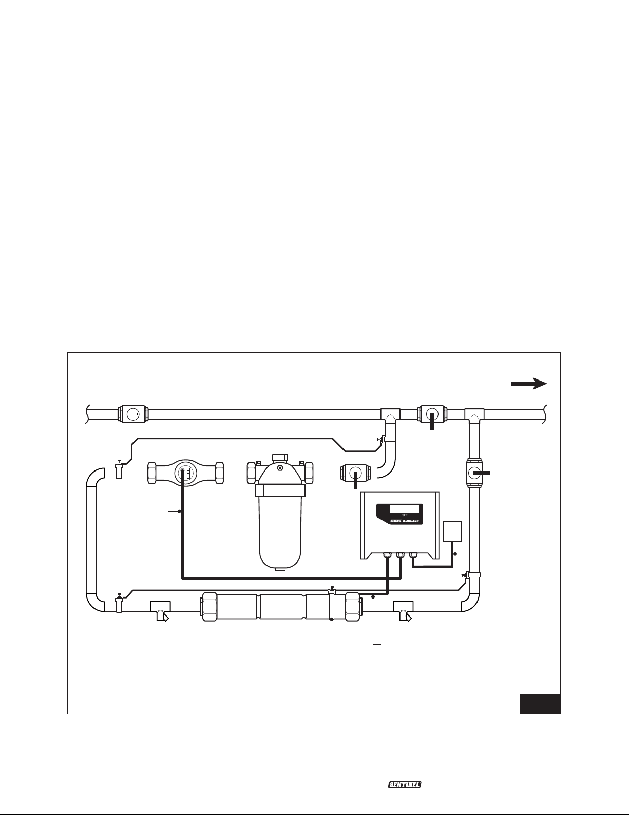
Schematic 1: Horizontal Pipe
For horizontal pipe mounted along a wall well above ground level.
This is the most typical installation where the incoming pipe to the building, or main feed to
the water system involved, is mounted on a wall and is a metre or more from the ground.
The installation point should allow full service access and should not be obscured by other
equipment.
Servicing the filter requires 50mm vertical clearance for removal of the filter bowl. There must
also be good access to the anode unit. Access for periodic inspection of electrical components
should also be available.
Water Flow Direction
NRV
Drain Drain
Anode Unit
Earth Strapping Clip
Anode Unit Supply Cable
Power Cable
Controller
Signal Cable
Fig. 3
 Loading...