

Page 1
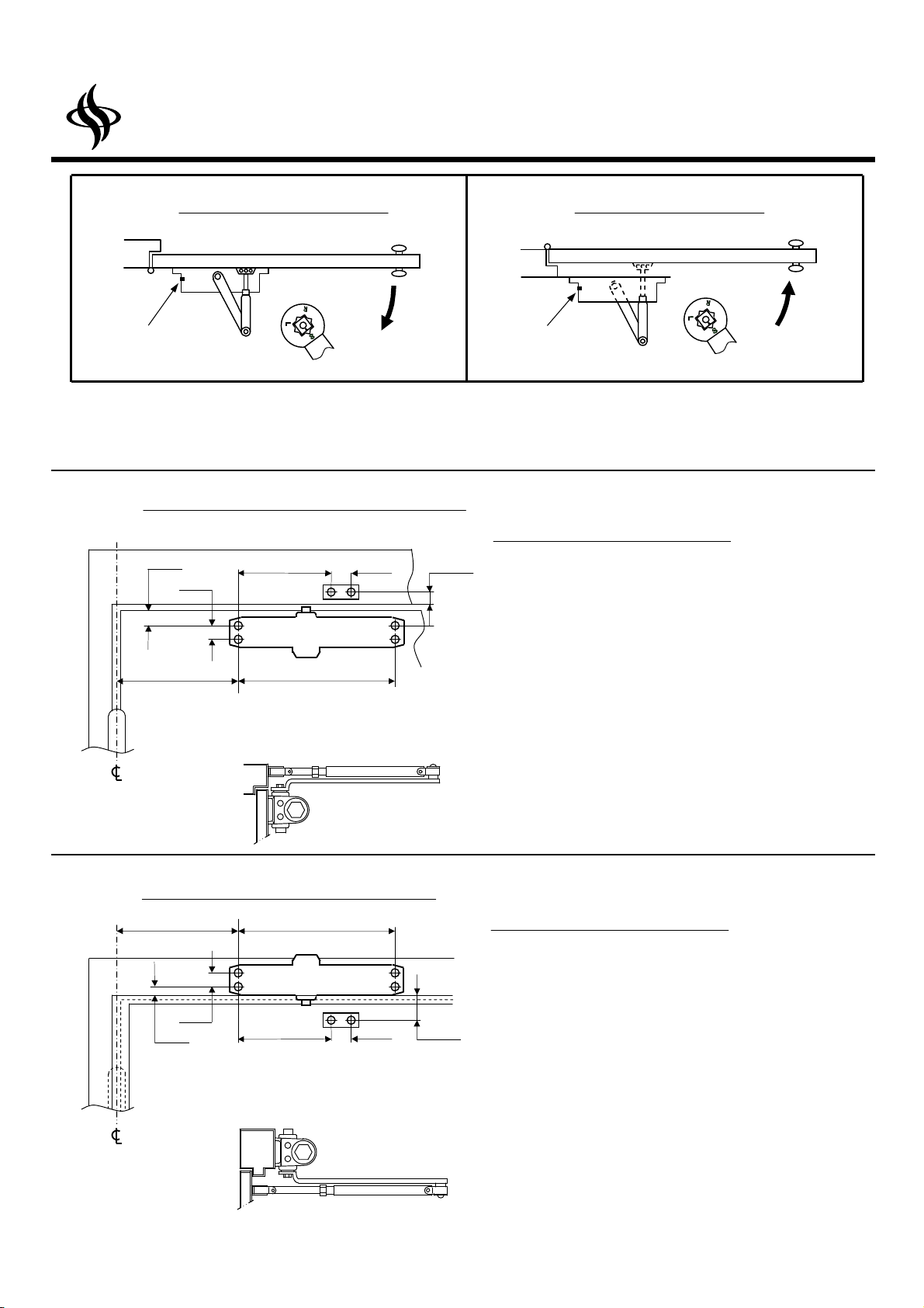
STANDARD (PULL SIDE) Mounting
TOP JAMB (PUSH SIDE) Mounting
This drawing is not to full scale. Therefore, do not use it as your template to locate the hole positions while you fabricate your
Hinge or Pivot
Hinge or Pivot
Instructions
SENTINEL
Installation
Series 5000
A
Type
Standard Installation
Right hand door
B
Type
Top Jamb Installation
Left hand door
SPEED
ADJUSTING
VALVE
PULL
side of door
SPEED
ADJUSTING
VALVE
PUSH
side of door
Please note
door and frame for the installation of this product. Instead, make the measurements needed manually without the use of the
enclosed template which is not to full scale.
AType
1
(25)
3/4
(19)
6 1/2
(165)
1 3/4
(44.4)
(25.4)
4
(101)
Right hand door shown.
Left hand door opposite.
Dimensions: inches (mm)
9 1/16
(230)
INSTALLATION INSTRUCTIONS
1. Using template dimensions shown above, mark FORE(4)
1
HOLES ON DOOR for door closer and TWO(2) HOLES
ON FRAME for arm shoe.
2. Drill pilot holes in door and frame for #14 all-purpose screws
or drill and tap for 1/4-20 machine screws.
3. Install adjustable forearm/arm shoe to frame using screws provided.
4. Mount closer on door using screws provided.
VALVE MUST BE POSITIONED TOWARD HINGE EDGE
5. Install main arm to top pinion shaft, perpendicular to door as shown
below. Secure tightly with arm screw/washer assembly provided.
6. Adjust length of forearm so that forearm is perpendicular to frame
when assembled to preloaded main arm(Illustration below).
Secure forearm to main arm with screw/washer assembly provided.
7. Adjust closing speed of door,
8. Snap pinion cap over shaft at bottom of closer.
SPEED ADJUSTING
.
BType
4
(101)
3/4
(19)
1/2
(12.7)
Left hand door shown.
Right hand door opposite.
Dimensions: inches (mm)
6 1/4
(159)
9 1/16
(230)
1 3/4
(44.4)
1 3/4
(44.4)
INSTALLATION INSTRUCTIONS
1. Using template dimensions shown above, mark FORE(4)
HOLES ON FRAME for door closer and TWO(2) HOLES
ON DOOR for arm shoe.
2. Drill pilot holes in door and frame for #14 all-purpose screws
or drill and tap for 1/4-20 machine screws.
3. Install adjustable forearm/arm shoe to door using screws provided.
4. Mount closer on frame using screws provided.
VALVE MUST BE POSITIONED TOWARD HINGE EDGE.
5. Install main arm to top pinion shaft, perpendicular to door as shown
below. Secure tightly with arm screw/washer assembly provided.
6. Adjust length of forearm so that forearm is perpendicular to door
when assembled to preloaded main arm(Illustration below).
Secure forearm to main arm with screw/washer assembly provided.
7. Adjust closing speed of door, Snap pinion cap over shaft at
bottom of closer.
SPEED ADJUSTING
Page 2
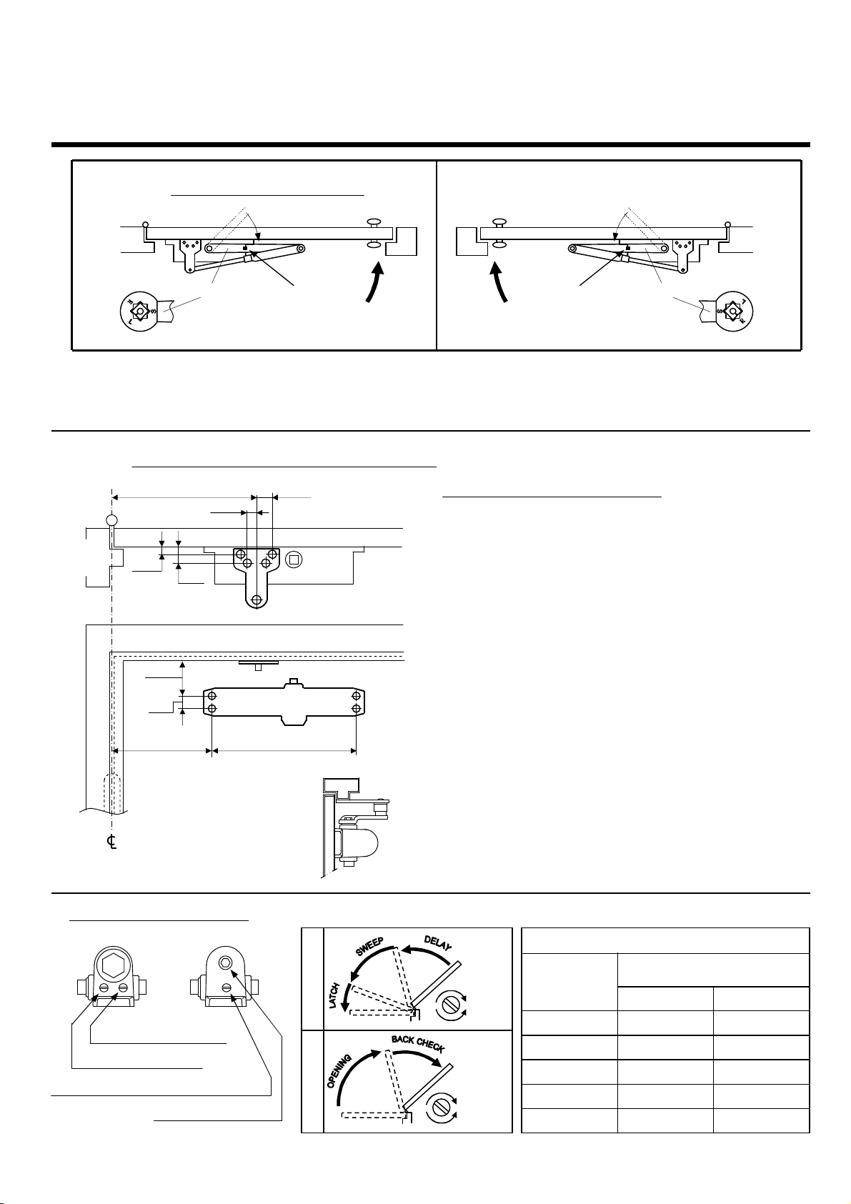
PARALLEL ARM (PUSH SIDE) Mounting
full scale. Therefore, do not use it as your template to locate the hole positions while you fabricate your
Hinge or Pivot
(121)
1
-8 -3
5000
5000BF
CLOCKWISE TURNS OF
Installation Instructions
C
Type
Please note
This drawing is not to
door and frame for the installation of this product. Instead, make the measurements needed manually without the use of the
enclosed template which is not to full scale.
Parallel Arm Installation
Left hand door
Main arm
SPEED
ADJUSTING
VALVE
side of door
PUSH
C
Type Opposite
Right hand door
PUSH
side of door
SPEED
ADJUSTING
VALVE
Series 5000
Main arm
CType
8 3/10
(211)
3/8
(9.5)
3 3/8
(86)
3/4
(19)
1
(25.5)
13/16
(20.5)
4 3/4
Left hand door shown.
Right hand door opposite.
Dimensions: inches (mm)
9 1/16
(230)
1 3/8
(35)
INSTALLATION INSTRUCTIONS
1. Using template dimensions shown above, mark FORE(4)
HOLES ON DOOR for door closer and FORE(4) HOLES
ON FRAME for parallel bracket.
2. Drill pilot holes in door and frame for #14 all-purpose screws or
drill and tap for 1/4-20 machine screws.
3. Install Parallel Arm Bracket shoe to frame using screws provided.
4. Mount closer on door using screws provided.
VALVE MUST BE POSITIONED TOWARD AWAY FROM HINGE
EDGE.
5. Install main arm to top pinion shaft, with arm pointing toward speed
adjusting screw. Secure tightly with arm screw/washer assembly provided.
6. Remove arm shoe from fore arm and discard. Install ROD end of fore
arm to bracket using screw/washer assembly provided. Adjust length
of fore arm to set arm elbow approximately 1-1/2"(38mm) from
door(refer to Illustration below). Attach fore arm to main arm by
rotating main arm away from door. Secure forearm to main arm using
screw/washer assembly provided.
7. Adjust length of fore arm so when it is attached to main arm the main
arm will be slightly away from parallel with closed door and assemble
at elbow then tighten locknut.
8. Adjust door closing speed by speed adjusting valves.
9. Snap pinion cap over shaft at bottom of closer.
SPEED ADJUSTING
CLOSER ADJUSTMENT
POWER ADJUSTMENT CHART
CLOSER
Slow
Closing cycle
SWEEP Adjusting Valve
LATCH Adjusting Valve
BACKCHECK or DELAY Adjusting Valve
Power Adjusting Nut
Opening cycle
Fast
Decreas
Increase
SIZE
2
3
4
5
ADJUSTING NUT
-
-4
0
6
12
0
6
-
 Loading...