


Mounting and operating instructions
RSTHM-2
COMBINED T AND RH
ROOM TRANSMITTER

www.sentera.eu
MIW-RSTHM-2-EN-000 - 15 / 01 / 2019 2 - 10
Table of contents
SAFETY AND PRECAUTIONS 3
PRODUCT DESCRIPTION 4
ARTICLE CODES 4
INTENDED AREA OF USE 4
TECHNICAL DATA 4
STANDARDS 4
OPERATIONAL DIAGRAMS 5
MOUNTING & OPERATING INSTRUCTIONS IN STEPS 5
OPERATING INSTRUCTIONS 7
VERIFICATION OF INSTALLATION INSTRUCTIONS 8
MODBUS REGISTER MAPS 8
TRANSPORT AND STORAGE 10
WARRANTY AND RESTRICTIONS 10
MAINTENANCE 10
RSTHM-2
COMBINED T AND RH
ROOM TRANSMITTER

www.sentera.eu
MIW-RSTHM-2-EN-000 - 15 / 01 / 2019 3 - 10
back to the table of contents
SAFETY AND PRECAUTIONS
Read all the information, the datasheet, mounting and operating instructions and
study the wiring and connection diagram before working with the product. For
personal and equipment safety, and for optimum product performance, make sure you
entirely understand the contents before installing, using, or maintaining this product.
For safety and licensing (CE) reasons, unauthorised conversion and / or
modifications of the product are inadmissible.
e product should not be exposed to abnormal conditions, such as: extreme
temperatures, direct sunlight or vibrations. Long-term exposure to chemical
vapours in high concentration can affect the product performance. Make sure the
work environment is as dry as possible; avoid condensation.
All installations shall comply with local health and safety regulations and local
electrical standards and approved codes. is product can only be installed by an
engineer or a technician who has expert knowledge of the product and safety
precautions.
Avoid contacts with energised electrical parts; always treat the product as if it is
live. Always disconnect the power supply before connecting, servicing or repairing
the product.
Always verify that you apply appropriate power supply to the product and use
appropriate wire size and characteristics. Make sure that all the screws and nuts
are well tightened and fuses (if any) are fitted well.
Recycling of equipment and packaging should be taken into consideration and these
should be disposed of in accordance with local and national legislation/regulations.
In case there are any questions that are not answered, please contact your
technical support or consult a professional.
RSTHM-2
COMBINED T AND RH
ROOM TRANSMITTER

www.sentera.eu
MIW-RSTHM-2-EN-000 - 15 / 01 / 2019 4 - 10
back to the table of contents
PRODUCT DESCRIPTION
e RSTHM-2 series are combined room transmitters which measure
temperature, relative humidity and ambient light. ey are Power over
Modbus supplied and all the parameters are accessible via Modbus RTU.
ARTICLE CODES
Code Supply Connection
RSTHM-2 24 VDC, PoM RJ45
INTENDED AREA OF USE
■
Monitoring indoor temperature and relative humidity in HVAC applications
■
Suitable for residential and commercial buildings
■
For indoor use only
TECHNICAL DATA
■
Maximum power consumption: 0,0,312 W
■
Nominal power consumption in normal operation: 0,0,234 W
■
Imax: 13 mA
■
Selectable temperature range: 0—50 °C
■
Selectable relative humidity range: 5—85 %
■
Ambient light sensor with adjustable ‘active’ and ‘standby’ level
■
Bootloader for updating the firmware via Modbus RTU communication
■
3 LEDs for status indication
■
Accuracy: ±0,4 °C (0—50 °C); ±3 % rH (5—85 % rH), depending on the selected
parameter
■
Enclosure:
►
rear plate: plastic ABS, black (RAL 9004)
►
front cover: ASA, ivory (RAL 9010)
■
Protection standard: IP30 (according to EN 60529)
■
Operating ambient conditions:
►
temperature: 0—50 °C
►
rel. humidity: 5—85 % rH, (non-condensing)
■
Storage temperature: -10—60 °C
RSTHM-2
COMBINED T AND RH
ROOM TRANSMITTER

www.sentera.eu
MIW-RSTHM-2-EN-000 - 15 / 01 / 2019 5 - 10
back to the table of contents
STANDARDS
■
Low Voltage Direc tive 2014/35/EC; EN 60529:1991; EN 60730-1:2011
■
EMC Directive 2014/30/EC; EN 60730-1:2011, EN 61000-6-1:2007, EN 61000-63:2007, EN 61326-1:2013, EN 61326-2-3:2013
■
WEE E 2012/ 19/ E C
■
RoHs Directive 2011/65/EC
OPERATIONAL DIAGRAMS
10
20
30
40
50
60
70
80
90
100
Minimum
range
Minimum
alert
Maximum
alert
Input r egister 1
or 2 [%]
T [°C ] / rH [%] *
Maximum
range
Out of
range
Wit hin
range
Alert rangeAlert rangeOut of
range
* LED ind ications r efer to T (def ault) or rH, de pending on th e selected p arameter
MOUNTING & OPERATING INSTRUCTIONS IN STEPS
Before you start mounting the RSTHM-2 room transmitter, read carefully “Safety
and Precautions”. Choose a smooth surface for installation (a wall, panel and etc.).
Follow these steps:
1. Using a flat screwdriver, remove the front white cover by releasing the snap-fits
on its both sides (see Fig. 1 Snap-fits release).
2. Inser t the crimped RJ45 cable through the opening on the rear plate and plug it
into the socket (see Fig. 2 Mounting dimensions).
3. Using suitable fastening materials (not supplied), position the room sensor at
least 1,5 m from the floor. When planning the installation, allow enough clearance
for maintenance and service. Mount the sensor in a well-ventilated area. Mind
the correct mounting position and unit dimensions. See Fig. 2 and Fig. 3.
RSTHM-2
COMBINED T AND RH
ROOM TRANSMITTER

www.sentera.eu
MIW-RSTHM-2-EN-000 - 15 / 01 / 2019 6 - 10
back to the table of contents
Fig. 1 Snap-fits release Fig. 2 Mounting dimension Fig. 3 Mounting position
2x Ø 6
59,8
9,8
74,5
104,5
20
104,5
25,6
70,5
Correct Incorrect
Posit ion at min. 1,5 m
from the floor
4. Do the wiring according to the wiring diagram (see Fig.4).
Fig. 4 Wiring diagram
RJ45
1234567
8
24 VDC GND A /B
Supply voltage
24 VDC
Ground
Modbus RTU
communication,
signal A
Modbus RTU
communication,
signal /B
/B
A
GND
24 VDC
8 mm
8 mm
8 mm
8 mm
RJ45
1
2
3
4
5
6
7
8
1
2
3
4
5
6
7
8
5. Put back the cover and snap it in.
6. Switch on the mains supply.
5.
RSTHM-2
COMBINED T AND RH
ROOM TRANSMITTER
www.sentera.eu
MIW-RSTHM-2-EN-000 - 15 / 01 / 2019 7 - 10
back to the table of contents
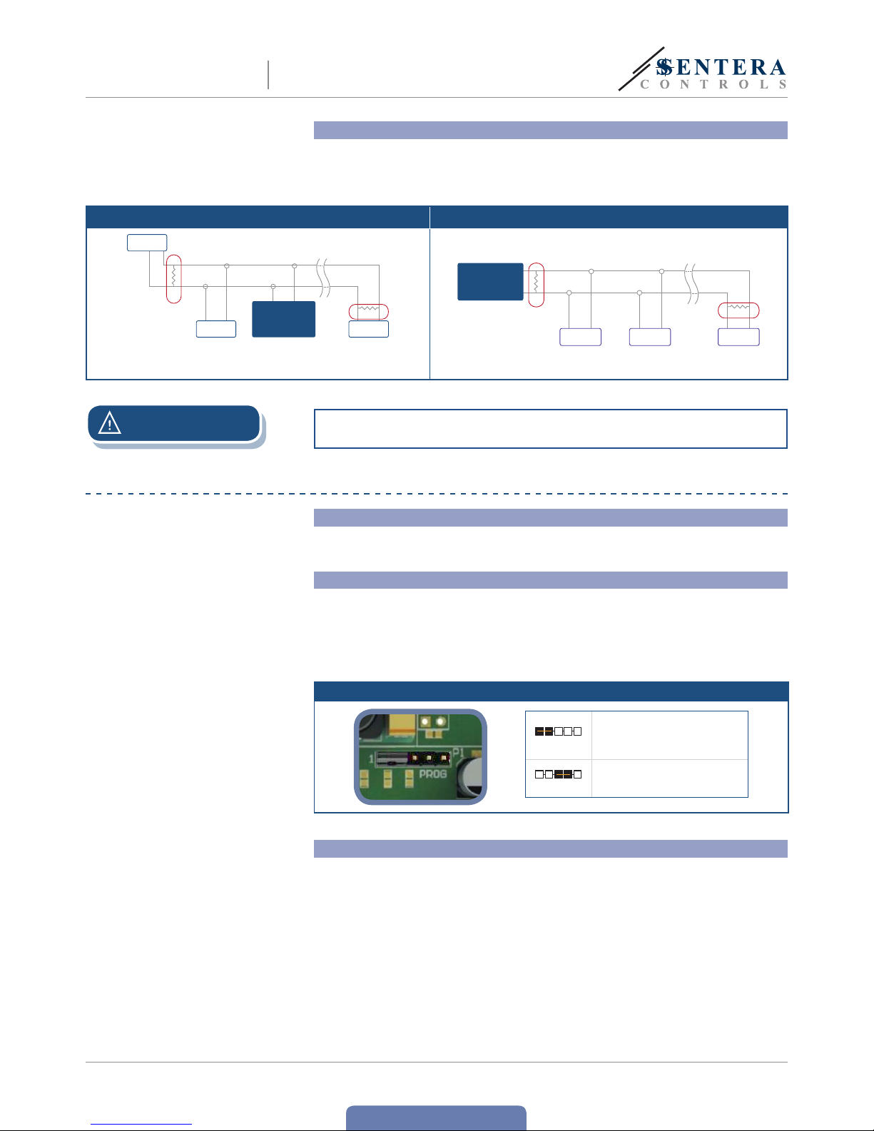
Optional settings
If your unit is the first or the last unit on the Modbus RTU network (see Example 1 and
Example2), enable the NBT resistor via 3SModbus or Sensistant (Holding Register 30).
If your device is not an end device, leave the NBT disabled (default Modbus setting).
Example 1 Example 2
RX
ТX
NBT
NBT
NBT
Slave 2
Master
Slave n
Slave 1
Slave 2
Slave 1
RX
ТX
NBT
NBT
Master
Slave n
ATTENTION
t
Do not expose to direct sunlight!
OPERATING INSTRUCTIONS
Calibration procedure:
Both the relative humidity and temperature sensor elements are factory calibrated.
Recalibration is not necessary.
Bootloader
anks to the bootloader functionality, the sensor firmware can be updated via
Modbus RTU communication. To enter ‘Boot mode”, put a jumper onto pins 3 and
4 of the P1 header and restart the power supply (see Fig. 5). Once ‘Boot mode’ is
activated, the firmware can be updated via SM Boot application (par t of 3SModbus
software suite) or Sensistant.
Fig. 5 P1 header
123 45
Put a jumper onto pins 1 and 2
and wait for at least 5 se conds to
reset the Modbus communication
parameters
123 45
Put a jumper onto pins 3 and 4
and restart the supply to enter
bootloader mode
LED indications
1. When the green LED is on, the measured value (temperature or relative humidity)
is between the minimum and maximum alert range values (Fig 6 - 1).
2. When the yellow LED is on, the measured value (temperature or relative humidity)
is in the alert range (Fig 6 - 2).
3. When the red LED is on, the measured value (temperature or relative humidity)
is below the minimum measurement range value or above the maximum value.
Blinking red LED indicates loss of communication with a sensor (Fig 6 - 3).
RSTHM-2
COMBINED T AND RH
ROOM TRANSMITTER

www.sentera.eu
MIW-RSTHM-2-EN-000 - 15 / 01 / 2019 8 - 10
back to the table of contents
Fig. 6 LED indications
3
2
1
NOTE
By default, the LED indication refers to temperature measurements. is can be
changed to relative humidity values via Modbus Holding Register 26 (see Ta ble
Holding registers below).
Ambient light sensor
It measures the ambient light levels in order to activate or deactivate Input Register 6.
ere are two Holding Registers for setting Active or Standby light level in luxes.
■
If the measured light level is below the Standby level, Input Register 6 indicates “Standby”.
■
If the measured ambient light level is above the Active level, Input Register 6
indicates “Active”.
■
If the measured ambient light level is between the Active and Stand-by level, Input
Register 6 indicates “Low intensity”, therefore it is advisable to set Active and
Standby levels in Holding Registers 34 and 35 according to the ambient lighting.
VERIFICATION OF INSTALLATION INSTRUCTIONS
After switching on the power supply one of the LEDs light up according to the status
of the measured variable. If this is not the case, check the connections.
RSTHM-2
COMBINED T AND RH
ROOM TRANSMITTER

www.sentera.eu
MIW-RSTHM-2-EN-000 - 15 / 01 / 2019 9 - 10
back to the table of contents
MODBUS REGISTER MAPS
INPUT REGISTERS
Data type Description Data Values
1 Temperature reading signed int. Actual temperature level -300—700 500 = 50,0 °C
2 Relative humidity level unsigned int. Actual relative humidity level 0—1.000 1.000 = 100,0 % rH
3 Dew point signed int. Calculated dew point -700—700 200 = 20,0 °C
4 Reser ved, retu rns “0”.
5 Ambient light intensity unsigned int. Measured light intensity 0—32.000 1.000 = 1.000 lx
6 Acti ve / stan dby unsigned int.
Act ive or Standby indicat ion acco rding t he Act ive /
Standby light level defined via holding registers 34
and 35. If t he meas ured light leve l is bet ween the
two le vels th e indication is 0 ( Low intens ity)
0—2
0 =
1 =
2 =
Low light intensit y
Active
Standby
7—10 Reser ved, retu rn “0”.
11
Outp ut valu e 1
(temperature)
unsigned int. An alog output va lue for tempera ture (T ) 0—1.000
0 =
1.000 =
0 %
100 %
12
Output value 2 (relative
humidity)
unsigned int. Anal og outp ut value for rel ative h umidity (rH) 0—1.000
0 =
1.000 =
0 %
100 %
13 Reser ved, retu rns “0”.
14 Temperature alert flag unsigned int.
Flag i ndicate s that measu red tempe rature is o utside
set al ert va lues. Se t to ‘1’ when t he measu red value
is outside the temperature alert values defined by
holding registers 20 and 21.
0—1
0 =
1 =
Measured temperature is OK
Measured temperature is too high/ low
15 Relative humidity alert flag unsigned int.
Flag indicates that measured relative humidity
is out side se t alert v alues . Set to ‘1’ wh en the
measured value is outside the relative humidity alert
values defined by holding registers 22 and 23.
0—1
0 =
1 =
Measu red rH is OK
Measu red rH is t oo high/ l ow
16 Reser ved, return “0”.
17 Temperature range limit flag unsigned int.
Flag i ndicate s that measu red tempe rature is o utside
set range limit values. Set to ‘1’ when the m easured
value is outside the temperature range limit values
defined by holding registers 14 and 15.
0—1
0 =
1 =
Temperature range is OK
Tempera ture range is too high/ lo w
18
Relative humidity range
limit flag
unsigned int.
Flag i ndicates tha t measur ed rela tive humidit y is
outside set range limit values. Set to ‘1’ when the
measured value is outside the relative humidity limit
range values defined by holding registers 16 and 17.
0—1
0 =
1 =
rH ran ge is OK
rH ran ge is too hi gh/ low
19 Reser ved, returns “0”.
20
Humidity / temperature
sensor fault
unsigned int.
Flag i ndicates if th e commun ication wit h the
temperature and humidity sensor is lost.
0—1
0 =
1 =
No
Yes
21 Reserve d, retu rns “0”.
22 Ambi ent light senso r fault unsigned int.
Flag t hat shows if the c ommuni cation with t he
ambie nt ligh t sensor i s lost.
0—1
0 =
1 =
No
Yes
HOLDING REGISTERS
Data type Description Data Default Values
1 Device slave address unsigned int. Modbus device address 1—247 1
2 Mod bus baud r ate unsigned int. Modbus communication baud rate 0—6 2
0 =
1 =
2 =
3 =
4 =
5 =
6 =
4.800
9.60 0
19.2 00
38.400
57. 600
115. 200
230.400
3 Modbus parity mode unsigned int. Parity check mode 0—2 1
0 =
1 =
2 =
8N1
8E1
8O1
4 Device type unsigned int. Device typ e (Read only) RST HM-2 = 1094
5 HW version unsigned int. Hardwar e version of t he device (Read only) XXXX 0x0100 = HW ve rsion 1.00
6 FW version unsigned int. Firmwa re version o f the devic e (Read only) XXXX 0x0100 = FW ve rsion 1.00
7—13 Reser ved, retu rn “0”.
14
Minimum temperature
range
unsigned int.
Minimum value of the temperature
range; canno t be set hi gher than max.
temperature range minus 5ºC
0 — (Max . range — 50) 0 100 = 10,0 °C
15
Maximum temperature
range
unsigned int.
Maximum value of temperature
range; canno t be set lo wer than min.
tempe rature rang e plus 5ºC
(Min . range + 50) – 500 500 500 = 50,0 °C
RSTHM-2
COMBINED T AND RH
ROOM TRANSMITTER

www.sentera.eu
MIW-RSTHM-2-EN-000 - 15 / 01 / 2019 10 - 10
back to the table of contents
HOLDING REGISTERS
16
Minimum relative
humidity range
unsigned int.
Minimum value of the rH range; cannot be
set hi gher tha n max. rH r ange minus 5 %
50 — (Ma x. range — 50) 50 2 00 = 20,0 % rH
17
Maximum relative
humidity range
unsigned int.
Maximum valu e of rH ran ge; cannot be se t
lower t han min. rH range p lus 5%
(Min . range + 50) – 850 850 850= 85,0 % rH
18—19 Reser ved, retu rn “0”.
20
Minimum temperature
alert
unsigned int. Minimum temperature alarm value
Min. temperature range — Max.
temperature alarm
0 10 0 = 10,0 ºC
21
Maximum
temperature alert
unsigned int. Maximum temperature alarm value
Min. temperature alarm — Max.
temperature range
500 5 00 = 50,0 ºC
22
Minimum relative
humidity alert
unsigned int. Minimum relative humidity alarm value
Min. relative humidity range —
Max. relative humidity alarm
50 200 = 20,0 % rH
23
Maximum relative
humidity alert
unsigned int. Maximum relative humidity alarm value.
Min. relative humidity alarm —
Max. relative humidity range
850 850 = 85,0 % r H
24—25 Reser ved, re turn “0 ”.
26 L ED indic ation unsigned int.
LED ind ication rela ted to on e of the
parameters
1—2 1
1 =
2 =
Temperature
rH
27—29 Reser ved, retu rn “0”.
30
Modbu s netw ork
resistor termination
(NBT )
unsigned int.
Sets device a s ending t he line o r not by
connecting NBT
0—1 0
0 =
1 =
NBT disconnected
NBT connected
31—33 Rese rved , return “0”.
34 Ac tive ligh t level unsigned int.
e ambi ent lig ht level a bove which
‘Acti ve’ is in dicated in inpu t regis ter 6
0—32.000 100 100 = 100 l x
35 Standby light level unsigned int.
e ambi ent lig ht level b elow which
‘Standby’ is indicated in input register 6
0—32.000 10 10 = 10 lx
36
Modbus registers
reset
unsigned int.
Rese ts Modbus Holdin g regis ters to
default values. When finished this register
is automatic ally rese t to ‘0’
0—1 0
0 =
1 =
Idle
Reset Modbus registers
37—4 0 R eser ved, re turn “0 ”
If you want to find o ut more a bout Mo dbus over serial l ine, ple ase visi t: http://www.modbus.org/docs/Modbus_over_serial_line_V1_02.pdf
TRANSPORT AND STORAGE
Avoid shocks and extreme conditions; stock in original packing.
WARRANTY AND RESTRICTIONS
Two years fr om the delivery date against de fects in manufactur ing. Any modificatio ns
or alterations to the product af ter the date of publication relieve the manufacturer
of any responsibilities. e manufacturer bears no responsibility for any misprints or
mistakes in this data.
MAINTENANCE
In normal conditions this product is maintenance-free. If soiled, clean with a dry or
damp cloth. In case of heavy pollution, clean with a non-aggressive product. In these
circumstances the unit should be disconnected from the supply. Pay attention that
no fluids enter the unit. Only reconnect it to the supply when it is completelydry.
RSTHM-2
COMBINED T AND RH
ROOM TRANSMITTER
 Loading...