


COMBINED TEMPERATURE AND
RELATIVE HUMIDITY ROOM
RSTHX-2
Mounting and operating instructions
TRANSMITTER

COMBINED TEMPERATURE AND RELATIVE
RSTHX-2
HUMIDITY ROOM TRANSMITTER
Table of contents
SAFETY AND PRECAUTIONS 3
PRODUCT DESCRIPTION 4
ARTICLE CODES 4
INTENDED AREA OF USE 4
TECHNICAL DATA 4
STANDARDS 5
OPERATIONAL DIAGRAMS 5
WIRING AND CONNECTIONS 6
MOUNTING & OPERATING INSTRUCTIONS IN STEPS 6
OPERATING INSTRUCTIONS 8
VERIFICATION OF INSTALLATION INSTRUCTIONS 9
MODBUS REGISTER MAPS 9
TRANSPORT AND STORAGE 11
WARRANTY AND RESTRICTIONS 11
MAINTENANCE 11
MIW-RSTHX-2-EN-000 - 15 / 02 / 2018 2 - 11
www.sentera.eu

COMBINED TEMPERATURE AND RELATIVE
RSTHX-2
HUMIDITY ROOM TRANSMITTER
SAFETY AND PRECAUTIONS
Read all the information, the datasheet, mounting and operating instructions and
study the wiring and connection diagram before working with the product. For
personal and equipment safety, and for optimum product performance, make sure you
entirely understand the contents before installing, using, or maintaining this product.
For safety and licensing (CE) reasons, unauthor ised conversion and/ or modifications
of the product are inadmissible.
e product should not be exposed to abnormal conditions, such as: extreme
temperatures, direct sunlight or vibrations. Long-term exposure to chemical
vapours in high concentration can affect the product performance. Make sure the
work environment is as dry as possible; avoid condensation.
All installations shall comply with local health and safety regulations and local
electrical standards and approved codes. is product can only be installed by an
engineer or a technician who has expert knowledge of the product and safety
precautions.
Avoid contacts with energised electrical parts; always treat the product as if it is
live. Always disconnect the power supply before connecting, servicing or repairing
the product.
Always verify that you apply appropriate power supply to the product and use
appropriate wire size and charac teristics. Make sure that all the screws and nuts
are well tightened and fuses (if any) are fitted well.
Recycling of equipment and packaging should be taken into consideration and these
should be disposed of in accordance with local and national legislation/regulations.
In case there are any questions that are not answered, please contact your
technical support or consult a professional.
MIW-RSTHX-2-EN-000 - 15 / 02 / 2018 3 - 11
back to the table of contents
www.sentera.eu

COMBINED TEMPERATURE AND RELATIVE
RSTHX-2
HUMIDITY ROOM TRANSMITTER
PRODUCT DESCRIPTION
ARTICLE CODES
INTENDED AREA OF USE
e RSTHX-2 series are multifunctional room sensors which measure temperature, relative
humidity and ambient light. ey feature a wide range of low voltage power supply
and two analog / modulating outputs. All parameters are accessible via Modbus RTU.
Code Supply
RSTHG-2 18—34 VDC / 15—24 VAC ± 10 %
RSTHF-2 18—34 VDC
■
Monitoring indoor temperature and relative humidity in HVAC applications
■
Suitable for residential and commercial buildings
■
For indoor use only
TECHNICAL DATA
■
2 analog / modulating outputs:
►
0—10 VDCmode: min. load 50 k Ω (RL ≥ 50 kΩ)
►
0—20 mA: max. load 500 Ω (RL ≤ 500 Ω)
►
PWM (open-collector type): PWM Frequency: 1 kHz, min. load 50 kΩ (RL ≥ 50kΩ);
PWM voltage level 3,3 VDC or 12 VDC
■
Selectable temperature range: 0—50 °C
■
Selectable relative humidity range: 5—85 %
■
Ambient light sensor with adjustable ‘active’ and ‘standby’ level
■
3 LEDs for status indication
■
Accuracy: ± 0,4 °C (0—50 °C) and ± 3 % rH (5—85 % rH), depending on the selected
parameter
■
Enclosure:
►
rear plate: plastic ABS, black (RAL 9004)
►
front cover: ASA, ivory (RAL 9010)
■
Protection standard: IP30 (according to EN 60529)
■
Operating ambient conditions:
►
temperature: 0—50 °C
►
rel. humidity: 5—85 % rH, (non-condensing)
■
Storage temperature: -10—60 °C
MIW-RSTHX-2-EN-000 - 15 / 02 / 2018 4 - 11
back to the table of contents
www.sentera.eu

50
100
RSTHX-2
STANDARDS
COMBINED TEMPERATURE AND RELATIVE
HUMIDITY ROOM TRANSMITTER
■
Low Voltage Directive 2014/35/EC
►
EN 60529:1991 Degrees of protection provided by enclosures (IP Code)
Amendment AC:1993 to EN 60529
►
EN 60730-1:2011 Automatic electrical controls for household and similar use Part 1: General requirements
■
EMC direc tive 2014/30/EU:
►
EN 60730-1:2011 Automatic electrical controls for household and similar use Part 1: General requirements
►
EN 61000-6-1:2007 Electromagnetic compatibility (EMC) - Part 6-1: Generic
standards - Immunity for residential, commercial and light-industrial
environments
►
EN 61000-6-3:2007 Electromagnetic compatibility (EMC) - Part 6-3: Generic
standards - Emission standard for residential, commercial and light-industrial
environments Amendments A1:2011 and AC:2012 to EN 61000-6-3
►
EN 61326-1:2013 Electrical equipment for measurement, control and laboratory
use - EMC requirements - Part 1: General requirements
►
EN 61326-2-3:2013 Electrical equipment for measurement, control and
laboratory use - EMC requirements - Part 2-3: Particular requirements. Test
configuration, operational conditions and performance criteria for transducers
with integrated or remote signal conditioning
■
WEE E 2012/ 19/ E C
■
RoHs Directive 2011/65/EC
OPERATIONAL DIAGRAMS
Analog
output 1
[%]
90
80
70
60
50
40
30
20
10
0
* LED indicaon - T (default) and rH
Minimum
range
Out of
range
Aler t
range
Minimum
alert
Within
range
Maximum
alert
Aler t
range
Maximum
range
Out of
range
T, [°C ] / rH [%]
MIW-RSTHX-2-EN-000 - 15 / 02 / 2018 5 - 11
back to the table of contents
www.sentera.eu
59,8
20
70,5
COMBINED TEMPERATURE AND RELATIVE
RSTHX-2
HUMIDITY ROOM TRANSMITTER
WIRING AND CONNECTIONS
Article type RSTHF-2 RSTHG-2
VIN 18—34 VDC 18—34 VDC 15—24 VAC ±10%
GND Ground Common ground* AC ~*
A Modbus RTU (RS485), signal A Modbus RTU (RS485), signal A
/B Modbus RTU (RS485), signal /B Modbus RTU (RS485), signal /B
AO1
Analog / modulating output 1 for temperature
measurement (0—10 VDC / 0—20 mA / PWM)
GND Ground AO Common ground*
AO2
Analog / modulating output 2 for relative humidity
measurement (0—10 VDC / 0—20 mA / PWM)
GND Ground AO Common ground*
Connections Spring contact terminal blocks, cable cross sec tion: 1,5 mm
* Caution: Never connect the common ground of G type articles to other devices powered by a DC voltage. If an AC power supply is used with a unit on a Modbus
network, the GND terminal should NOT BE CONNECTED to other units on the network or via the CNVT-USB-RS485 converter. is may cause permanent damage to the
communication semiconductors and / or the computer!
Analog / modulating output 1 for temperature
measurement (0—10 VDC / 0—20 mA / PWM)
Analog / modulating output 2 for relative humidity
measurement (0—10 VDC / 0—20 mA / PWM)
2
MOUNTING & OPERATING INSTRUCTIONS IN STEPS
Before you start mounting the RSTHX-2 room sensor, read carefully “Safety and
Precautions”. Choose a smooth surface for installation (a wall, panel and etc.).
Follow these steps:
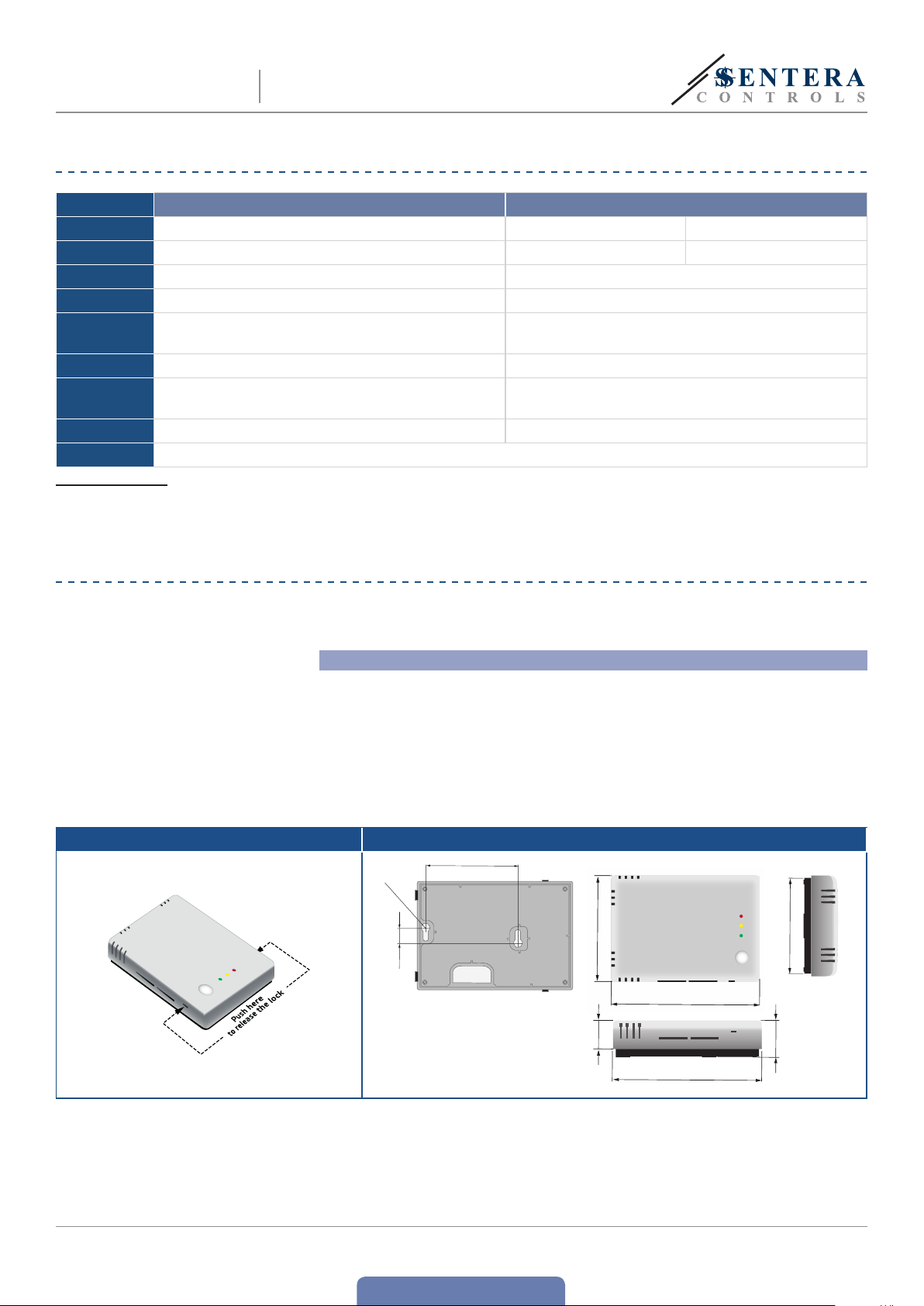
1. Using a flat screwdriver, remove the front white cover by releasing the snap-fits
on its both sides (see Fig. 1 Snap-fits release).
2. Insert the cables through the opening on the rear plate (See Fig. 2 Mounting
dimensions.)
3. Using suitable fastening materials (not supplied), position the room sensor at
least 1,5 m from the floor. When planning the installation, allow enough clearance
for maintenance and service. Mount the sensor in a well-ventilated area. Mind
the correct mounting position and unit dimensions. See Fig. 2 and Fig. 3.
Fig. 1 Snap-fits release Fig. 2 Mounting dimension
2x Ø 6
74,5
9,8
104,5
25,6
104,5
MIW-RSTHX-2-EN-000 - 15 / 02 / 2018 6 - 11
www.sentera.eu
back to the table of contents

RSTHX-2
COMBINED TEMPERATURE AND RELATIVE
HUMIDITY ROOM TRANSMITTER
Fig. 3 Mounting position
Correct Incorrect
Position at min. 1,5 m
from the floor
4. Do the wiring according to the wiring diagram (see Fig.4).
Fig. 4 Wiring and connections
Power supply
Modbus RTU
Analog /
modulating
output 1 - T
5. Put back the cover snap it in.
6. Switch on the mains supply.
5.
Optional settings
If your unit is the first or the last unit on the Modbus RTU network (see Example 1
and Example2), enable the NBT resistor via 3SModbus or Sensistant. If your device
is not an end device, leave the NBT disabled (default Modbus setting).
Example 1 Example 2
Slave 1
RX
NBT
NBT
Slave 2
Master
ТX
NBT
Slave n
Master
Analog / modulating
NBT
Slave 1
output 2 - rH
Slave 2
RX
ТX
NBT
Slave n
ATTENTION
If an AC power supply is used with any of the units on a Modbus network, the
GND terminal should NOT BE CONNECTED to other units on the network or
via the CNVT-USB-RS485 converter. is may cause permanent damage to the
communication semiconductors and/or the computer!
MIW-RSTHX-2-EN-000 - 15 / 02 / 2018 7 - 11
www.sentera.eu
back to the table of contents

RSTHX-2
COMBINED TEMPERATURE AND RELATIVE
HUMIDITY ROOM TRANSMITTER
ATTENTION
ATTENTION
CAUTION
Do not exceed the maximum power supply rating! Measure before installation!
Unregulated 24 VAC supply units provide higher nominal output voltage and
activate the integrated fuse protection.
We advise you not to use G and F-type articles together on the same network. If
G and F-type articles are used together on the same network, make sure you use
separate power supplies for both types. Always connect different article types to
separate AC transformers or use the same article version.
Do not expose to direct sunlight!
OPERATING INSTRUCTIONS
Calibration procedure:
Both the relative humidity and temperature sensor elements are factory calibrated.
Recalibration is not necessary.
Bootloader
anks to the bootloader functionality, the sensor firmware can be updated via
Modbus RTU communication. To enter ‘Boot mode”, put a jumper onto pins 3 and
4 of the P1 header and restart the power supply (see Fig. 5). Once ‘Boot mode’ is
activated, the firmware can be updated via SM Boot application (part of 3SModbus
software suite) or Sensistant.
Fig. 5 P1 header
Put a jumper onto pins 1 and 2 and wait
123 45
123 45
LED indications
1. When the green LED is on, the measured value (temperature or relative humidity)
is between the minimum and maximum alert range values (Fig 6 - 1).
2. When the yellow LED is on, the measured value (temperature or relative humidity)
is in the alert range (Fig 6 - 2).
3. When the red LED is on, the measured value (temperature or relative humidity)
is below the minimum measurement range value or above the maximum value.
Blinking red LED indicates loss of communication with a sensor (Fig 6 - 3).
Fig. 6 LED indications
for at least 5 se conds to reset t he Modbus
Put a jumper onto pins 3 and 4 and restart
communication parameters
the supply to enter bootloader mode
3
2
1
MIW-RSTHX-2-EN-000 - 15 / 02 / 2018 8 - 11
back to the table of contents
www.sentera.eu

RSTHX-2
COMBINED TEMPERATURE AND RELATIVE
HUMIDITY ROOM TRANSMITTER
NOTE
By default, the LED indication refers to temperature measurements. is can be
changed to relative humidity via Modbus Holding Register 26 (see Tabl e Holding
registers below).
Ambient light sensor
e measured light intensity in luxes is available in Input Register 5. Additionally,
an active and standby level can be defined in Holding registers 34 and 35. Input
Register 6 indicates if the measured value is below standby level, above active level
or in between both levels:
■
If the measured light level is below the Standby level, Input Register 6 indicates
“Standby”.
■
If the measured ambient light level is above the Active level, Input Register 6
indicates “Active”.
■
If the measured ambient light level is between the active and stand-by level, Input
Register 6 indicates “Low intensity”. When this feature is used, it is advisable to
adjust the active and standby levels in Holding Registers 34 and 35 according to
the actual ambient light conditions around the sensor.
VERIFICATION OF INSTALLATION INSTRUCTIONS
After switching on the power supply one of the LEDs lights up according to the
status of the measured variable. If this is not the case, check the connections.
MODBUS REGISTER MAPS
INPUT REGISTERS
Data type Description Data Values
1 Temperature signed int. Actual temperature level -300—700 500 = 50,0 °C
2 Relative humidity unsigned int. Actual relative humidity level 0—1.000 1.000 = 100,0 % rH
3 Dew point signed int. Calculated dew point -700—700 200 = 20,0 °C
4 CO
5 Ambient light intensity unsigned int. Measured light intensity 0—32.000 1.000 = 1.000 lx
6 Act ive / sta ndby unsigned int.
7—10 Reser ved, retu rn “0”
11
12
13 Reser ved, retu rns “0”
14 Temperature alert flag unsigned int.
15 Relative humidity alert flag unsigned int.
16 Reser ved, returns “0”
17 Temperature range limit flag unsigned int.
18
19 Reser ved, returns “0”
20
21 Reserve d, returns “0”
22 Ambi ent ligh t sensor f ault unsigned int.
2
Anal og outpu t value 1
(temperature)
Anal og output v alue 2 (relat ive
humidity)
Relative humidity range
limit flag
Humid ity / tem perat ure
sensor fault
unsigned int. Act ual CO2 level 400—2.000 2.000 = 2.000 ppm
Act ive or Sta ndby indicatio n according the Active /
Stand by light l evel defi ned via ho lding re gisters 34 and
35. If the measur ed light l evel is be tween t he two le vels,
the indicati on is “0” ( Low intensity)
unsigned int. Anal og outpu t value for t empera ture (T ) 0—1.000
unsigned int. Anal og output v alue for rel ative humi dity (rH ) 0—1.000
Flag i ndicat es that m easure d temper ature i s outside
set al ert val ues. Se t to ‘1’ when th e measur ed value i s
outside the temperature alert values defined by holding
regi sters 20 and 21
Flag i ndicat es that m easure d relat ive humi dity is o utsid e
set al ert val ues. Se t to ‘1’ when th e measur ed value i s
outside the relative humidity alert values defined by
holding registers 22 and 23
Flag i ndicat es that m easure d temper ature i s outside set
range limit va lues. Se t to ‘1’ when t he measured valu e
is outside the temperature range limit values defined by
holding registers 14 and 15
Flag i ndicat es that m easure d relat ive humi dity is o utsid e
unsigned int.
unsigned int.
set ra nge limit v alues. Se t to ‘1’ when the me asured va lue
is outside the relative humidity limit range values defined
by holding registers 16 and 17
Flag indicates if the communication with the temperature
and hum idity s ensor is l ost
Flag t hat show s if the co mmunic ation w ith the a mbient
light sensor is l ost
0—2
0—1
0—1
0—1
0—1
0—1
0—1
0 =
1 =
2 =
0 =
1.000 =
0 =
1.000 =
0 =
1 =
0 =
1 =
0 =
1 =
0 =
1 =
0 =
1 =
0 =
1 =
Low light intensity
Measu red temp eratu re is OK
Measu red temp eratu re is too hi gh/ low
Measu red rH is OK
Measu red rH is too high/ lo w
Temperature range is OK
Tempera ture ra nge is too high/ low
rH ran ge is too hig h/ low
Active
Standby
100 %
100 %
rH ran ge is OK
0 %
0 %
Yes
Yes
No
No
MIW-RSTHX-2-EN-000 - 15 / 02 / 2018 9 - 11
www.sentera.eu
back to the table of contents

RSTHX-2
COMBINED TEMPERATURE AND RELATIVE
HUMIDITY ROOM TRANSMITTER
HOLDING REGISTERS
1 Device slave address unsigned int. Modbus device address 1—247 1
2 Modbus baud rate unsigned int. Modbus communication baud rate 0—6 2
3 Modbus parity mode unsigned int. Parity check mode 0—2 1
4 Device type unsigned int. Device type (Read only) RSTHX-2= 1093
5 HW version unsigned int. Hard ware version of the d evice (Read only) XXXX 0x 0100 = HW ve rsion 1.00
6 F W version unsigned int. Firmwar e version o f the device (Read only) XXXX 0x 0100 = FW versi on 1.00
7 Reser ved, retu rns “0”
8 O utput 1 over write ( T) unsigned int. Enables the direct control over the temperature output. 0 —1 0
9 O utput 2 over write (r H) unsigned int. Enables t he direct control over the r H output 0—1 0
10 Reser ved, retu rns “0”
11 O utput 1 ty pe (T ) unsigned int. Selec t analog / dig ital ou tput ty pe 1—3 1
12 Output 2 t ype (rH) unsigned int. Select a nalog / digital ou tput t ype 1—3 1
13 Rese rved, r eturns “0”
Minimum temperature
14
range
Maximum temperature
15
range
Minimum relative humidity
16
range
Maximum relative humidity
17
range
18—19 Reser ved, retu rn “0”
Minimum temperature
20
alert
Maximum temperature
21
alert
Minimum relative humidity
22
alert
Maximum relative
23
humidity alert
24—25 Reser ved, return “0”
26 LED indic ation unsigned int. L ED indic ation r elated to one of th e parame ters 1—3 1
Internal voltage source
27
selec tion Output 1 (T )
Internal voltage source
28
selec tion Output 2 (rH)
29 Reser ved, retu rn “0”
Modbu s netwo rk resi stor
30
termination (NBT)
Outp ut 1 over write
31
value (T )
Outp ut 2 over write val ue
32
(rH)
33 Rese rved, r eturns “0”
34 Ac tive ligh t level unsigned int.
35 Standby light level unsigned int.
36 M odbus re gister s reset unsigned int.
37—4 0 Re serve d, retu rn “0”
If you w ant to find o ut more ab out Modb us over se rial lin e, please v isit: http://www.modbus.org/docs/Modbus_over_serial_line_V1_02.pdf
Data type Description Data Default Values
unsigned int.
unsigned int.
unsigned int.
unsigned int.
unsigned int. Minimum temperature alarm value
unsigned int. Max imum temperature alarm value
unsigned int. Minimum relative humidity alarm value
unsigned int. Max imum relative humidity alarm value
unsigned int. S electio n of inter nal voltag e source for P WM output 1 0—1 0
unsigned int. S electio n of inter nal voltag e source for P WM output 2 0—1 0
unsigned int. S et devi ce as ending the lin e or not by co nnect ing NBT 0 —1 0
unsigned int.
unsigned int.
Minimum value of the temperature range; cannot be set
higher than max. temperature range minus 5ºC
Maximum value of temperature range; cannot be set lower
than min. temperature range plus 5ºC
Minimum value of the rH range; cannot be set higher
than max. rH range minus 5 %
Maximum value of rH rang e; canno t be set lo wer than
min. rH range plus 5%
Over write value for ou tput 1. Ac tive onl y if Holding
regi ster 8 is se t to 1
Over write value for ou tput 2. Ac tive only i f Holding
regi ster 9 is se t to 1
e ambi ent ligh t level above w hich ‘Ac tive’ is indica ted
in inpu t register 6
e ambi ent ligh t level below w hich ‘St andby ’ is
indicated in input register 6
Rese ts Modbu s Holding r egisters to defau lt values.
When fi nished t his regi ster is au tomat ically r eset to ‘0’
0 — (Max . range — 50) 0 100 = 10,0 °C
(Min . range + 50) – 500 500 500 = 50,0 °C
50 — (Ma x. range — 50) 50 200 = 20,0 % rH
(Min . range + 50) – 850 850 850= 85,0 % r H
Min. temperature range — Max.
temperature alarm
Min. temperature alarm — Max.
temperature range
Min. relative humidity range —
Max. relative humidity alarm
Min. relative humidity alarm —Max.
relative humidity range
0—1.000 0
0—1.000 0
0—32.000 100 1.000 = 1.000 lx
0—32.000 10 10 = 10 l x
0—1 0
0 10 0 = 10, 0 ºC
500 500 = 50 ,0 ºC
50 200 = 20,0 % rH
850 850 = 85,0 % rH
1.000 =
1.000 =
0 =
1 =
2 =
3 =
4 =
5 =
6 =
0 =
1 =
2 =
0 =
1 =
0 =
1 =
1 =
2 =
3 =
1 =
2 =
3 =
1 =
2 =
0 =
1 =
0 =
1 =
0 =
NBT disconnected
1 =
0 =
0 =
0 =
1 =
4.800
9.600
19.200
38.400
57.600
115.200
230.400
8N1
8E1
8O1
Disabled
Enabled
Disabled
Enabled
1—10 V DC
0—20 m A
PWM
1—10 V DC
0—20 m A
PWM
temperature
3,3 VDC
12 V DC
3,3 VDC
12 V DC
NBT connected
0 %
100 %
0 %
100 %
Idle
Rese t Modbus
registers
rH
MIW-RSTHX-2-EN-000 - 15 / 02 / 2018 10 - 11
www.sentera.eu
back to the table of contents

COMBINED TEMPERATURE AND RELATIVE
RSTHX-2
HUMIDITY ROOM TRANSMITTER
TRANSPORT AND STORAGE
Avoid shocks and extreme conditions; stock in original packing.
WARRANTY AND RESTRICTIONS
Two years from the delivery date against defects in manufactur ing. Any modifications
or alterations to the product after the date of publication relieve the manufacturer
of any responsibilities. e manufacturer bears no responsibility for any misprints or
mistakes in this data.
MAINTENANCE
In normal conditions this product is maintenance-free. If soiled, clean with a dr y or
damp cloth. In case of heavy pollution, clean with a non-aggressive product. In these
circumstances the unit should be disconnected from the supply. Pay attention that
no fluids enter the unit. Only reconnect it to the supply when it is completelydry.
MIW-RSTHX-2-EN-000 - 15 / 02 / 2018 11 - 11
back to the table of contents
www.sentera.eu
 Loading...