

Page 1

MULTIFUNCTIONAL LOGIC
MCS -1-LCD
Mounting and operating instructions
CONTROLLER
Page 2

MULTIFUNCTIONAL LOGIC
MC S -1- LC D
CONTROLLER
Table of contents
SAFETY AND PRECAUTIONS 4
PRODUCT DESCRIPTION 5
ARTICLE CODES 5
INTENDED AREA OF USE 5
TECHNICAL DATA 5
STANDARDS 6
WIRING AND CONNECTIONS 6
OPERATIONAL DIAGRAMS 7
MOUNTING INSTRUCTIONS IN STEPS 8
VERIFICATION OF THE CORRECT INSTALLATION . . . . . . . . . . . . . . . . .10
OPERATING INSTRUCTIONS 12
CONTROLLER OVERVIEW . . . . . . . . . . . . . . . . . . . . . . . . . . . . . . .12
CONTROL FUNCTIONS OVERVIEW . . . . . . . . . . . . . . . . . . . . . . . . .12
PARAMETERS AND DEFAULT SETTINGS . . . . . . . . . . . . . . . . . . . . . .14
MIW- MC S -1-LCD- E N - 00 0 - 20 / 07 / 2016 2 - 33
www.sentera.eu
Page 3

MULTIFUNCTIONAL LOGIC
MC S -1- LC D
CONFIGURING THE PARAMETERS 15
USING PREDEFINED TEMPLATES . . . . . . . . . . . . . . . . . . . . . . . . . .16
CUSTOMISING THE SETTINGS . . . . . . . . . . . . . . . . . . . . . . . . . . . .17
3SMONITOR SOFTWARE. . . . . . . . . . . . . . . . . . . . . . . . .17
3SMODBUS SOFTWARE . . . . . . . . . . . . . . . . . . . . . . . . .18
4-BUTON KEYBOARD INTERFACE . . . . . . . . . . . . . . . . . . .19
MAIN MENU STRUCTURE . . . . . . . . . . . . . . . . . . . . . . . . . . . . . .20
DEVICE FUNCTIONALITY SELECTION . . . . . . . . . . . . . . . . .21
ANALOGUE INPUTS SETUP . . . . . . . . . . . . . . . . . . . . . . .22
DIGITAL INPUTS SETUP . . . . . . . . . . . . . . . . . . . . . . . . .23
CONTROLLER
ANALOGUE OUTPUTS SETUP . . . . . . . . . . . . . . . . . . . . . .24
RELAY CONTACT SETUP . . . . . . . . . . . . . . . . . . . . . . . . .25
SCHEDULE . . . . . . . . . . . . . . . . . . . . . . . . . . . . . . . . .26
RUN SETTINGS . . . . . . . . . . . . . . . . . . . . . . . . . . . . . .27
MODBUS REGISTER MAPS . . . . . . . . . . . . . . . . . . . . . . . . . . . . . .28
TRANSPORT AND STOCK KEEPING INFORMATION 33
WARRANTY INFORMATION AND RESTRICTIONS 33
MAINTENANCE 33
MIW- MC S -1-LCD- E N - 00 0 - 20 / 07 / 2016 3 - 33
www.sentera.eu
Page 4
MULTIFUNCTIONAL LOGIC
MC S -1- LC D
CONTROLLER
SAFETY AND PRECAUTIONS
Read all information, the datasheet, mounting instructions and wiring scheme
before working with the product. For personal and equipment safety, and for
optimum product performance, make sure you entirely understand the contents
before installing, using, or maintaining this product.
For safety and licensing (CE) reasons, unauthorised conversion and/ or modifications
to the product are not permitted.
e product must not be exposed to abnormal conditions, such as: extreme
temperatures, direc t sunlight or vibrations. Chemical vapours with high concentration
in combination with long exposure times can affect the product performance. Make
sure the work environment is as dry as possible; check for condensation spots.
All installations shall comply with the local health and safety regulations and local
electrical codes. is product can only be installed by an engineer or a technician
who has an expert knowledge of the product and safety precautions.
Avoid contacts with energised electrical parts; always treat the product as if it
is life. Always disconnect the power source before connecting the power cables,
servicing or repairing the product.
Always verify that you apply appropriate power supply to the product and use wires
with appropriate size and characteristics. Make sure that all the screws and nuts are
well tightened and fuses (if any) are fitted well.
Recycling of equipment and packaging should be taken into consideration and
disposed in accordance with local and national legislation/regulations.
In case there are any questions that are not answered, please contact your technical
support or consult a professional.
MIW- MC S -1-LCD- E N - 00 0 - 20 / 07 / 2016 4 - 33
www.sentera.eu
back to the table of contents
Page 5
MC S -1- LC D
PRODUCT DESCRIPTION
ARTICLE CODES
INTENDED AREA OF USE
MULTIFUNCTIONAL LOGIC
CONTROLLER
e MCS-1-LCD multifunctional logic controller has integrated analogue, digital
and relay outputs which are free configurable. Its multiple analogue, digital and
temperature inputs ensure functionality in a large range of HVAC applications. All
functional parameters and settings are accessible either via a 4-button interface
with LCD display, via a user-friendly monitoring software application for Windows or
via 3SModbus. A bootloader makes firmware updates via USB possible.
Code Supply
MC S -1-LC D 85—264 VAC / 47—63 Hz
■
Fan speed control and monitoring
■
Air curtain control
■
Advanced HVAC systems for maintaining stable environment and improved
comfort
■
For indoor use only
TECHNICAL DATA
Temperature inputs
■
2 temperature inputs: PT500 & PT1000 compatible (automatic detection)
Analogue inputs
■
2 analogue inputs Ai1 and Ai2: (0—10 VDC / 2—10 VDC / 0—20 mA / 4—20 mA / PWM)
►
Input impedance (0—10 VDC mode): 136 kΩ
►
Input impedance (0—20 mA mode): 505 Ω
►
Input impedance (PWM mode): 131 kΩ
Digital inputs
■
4 digital inputs
Analogue outputs
■
2 analogue outputs: (0—10 VDC / 2—10 VDC / 0—20 mA / 4—20 mA / PWM)
►
Load resistance in 0—10 VDC mode: ≥ 50 kΩ
►
Load resistance in 0—20 mA mode: ≤ 500 Ω
►
Load resistance in PWM mode: ≥ 50 kΩ
Relay outputs
■
2 relay outputs: C/O, 250 VAC / 16 A (resistive load)
PWM outputs
■
Internally supplied (Fig. 3a) or
■
Open collector (Fig. 3b)
Supply outputs
■
1 supply output: 24 VDC / 200 mA
Other specifications
■
Leakage current: < 0,25 mA
■
Power consumption:
►
no load: max. 2 W
►
full load: max. 11 W
■
USB 2.0 interface
■
Modbus RTU (RS485) communication
MIW- MC S -1-LCD- E N - 00 0 - 20 / 07 / 2016 5 - 33
back to the table of contents
www.sentera.eu
Page 6
MULTIFUNCTIONAL LOGIC
MC S -1- LC D
CONTROLLER
■
Enclosure:
►
►
■
Operating ambient conditions:
►
►
■
Storage temperature: -10—50 °C
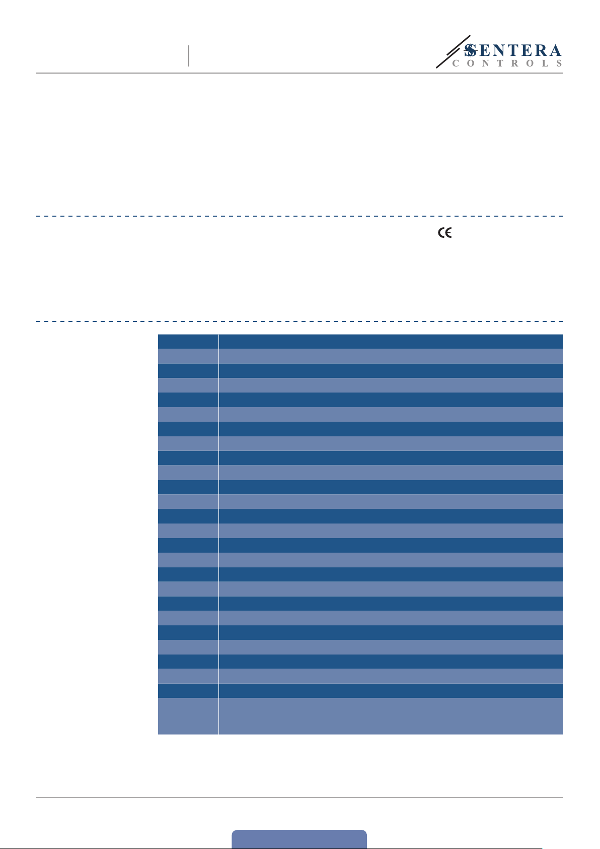
STANDARDS
■
Low Voltage Directive 2014/35/EC
■
EMC Directive 2014/30/EC: EN 61326
■
WEE E Directive 2012/19/EU
■
RoHs Directive 2011/65/EU
WIRING AND CONNECTIONS
ABS plastic, grey (RAL7035)
IP54 (according to EN 60529)
temperature: 0—40 °C
rel. humidity: 0—80 % rH (non-condensing)
L Power supply, Line
N Power supply, Neutral
NC1 Normally closed contact, relay 1
COM1 Common contact, relay 1
NO1 Normally open contact, relay 1
NC2 Normally closed contact, relay 2
COM2 Common contact, relay 2
NO2 Normally open contact, relay 2
T1 Temperature input 1 (PT500 or PT1000)
GND Ground, common ground reference for T1 and T2
T2 Temperature input 2 (PT500 or PT1000)
Ai1 Analogue input 1 (0—10 VDC / 2—10 VDC / 0—20 mA / 4—20 mA / PWM)
GND Ground, common ground reference for Ai1 and Ai2
Ai2 Analogue input 2 (0—10 VDC / 2—10 VDC / 0—20 mA / 4—20 mA / PWM)
Di1 Digital input 1 (GND reference)
Di2 Digital input 2 (GND reference)
Di3 Digital input 3 (GND reference)
Di4 Digital input 4 (GND reference)
Ao1 Analogue output 1 (0—10 VDC / 2—10 VDC / 0—20 mA / 4—20 mA / PWM)
GND Ground, common ground reference for Ao1 and Ao2
Ao2 Analogue output 2 (0—10 VDC / 2—10 VDC / 0—20 mA / 4—20 mA / PWM)
GND Ground reference for supply output
+24 V D C Supply output (24 VDC / 200 mA)
/B Modbus RTU (RS485) signal /B
A Modbus RTU (RS485) signal /A
2
Connections
Cable cross section: max. 1,5 / 2,5 mm
Cable gland clamping range: 3—6 mm
2 USB sockets, type Mini B
MIW- MC S -1-LCD- E N - 00 0 - 20 / 07 / 2016 6 - 33
back to the table of contents
www.sentera.eu
Page 7
[x]
A
A
[x]
A
t,[s ]
Tix/Aix,
t,[s ]
[x]
A
t, [s]
Ti
t, [s]
A
ox, [%]
t,[s]
A
ox, [%]
MULTIFUNCTIONAL LOGIC
MC S -1- LC D
CONTROLLER
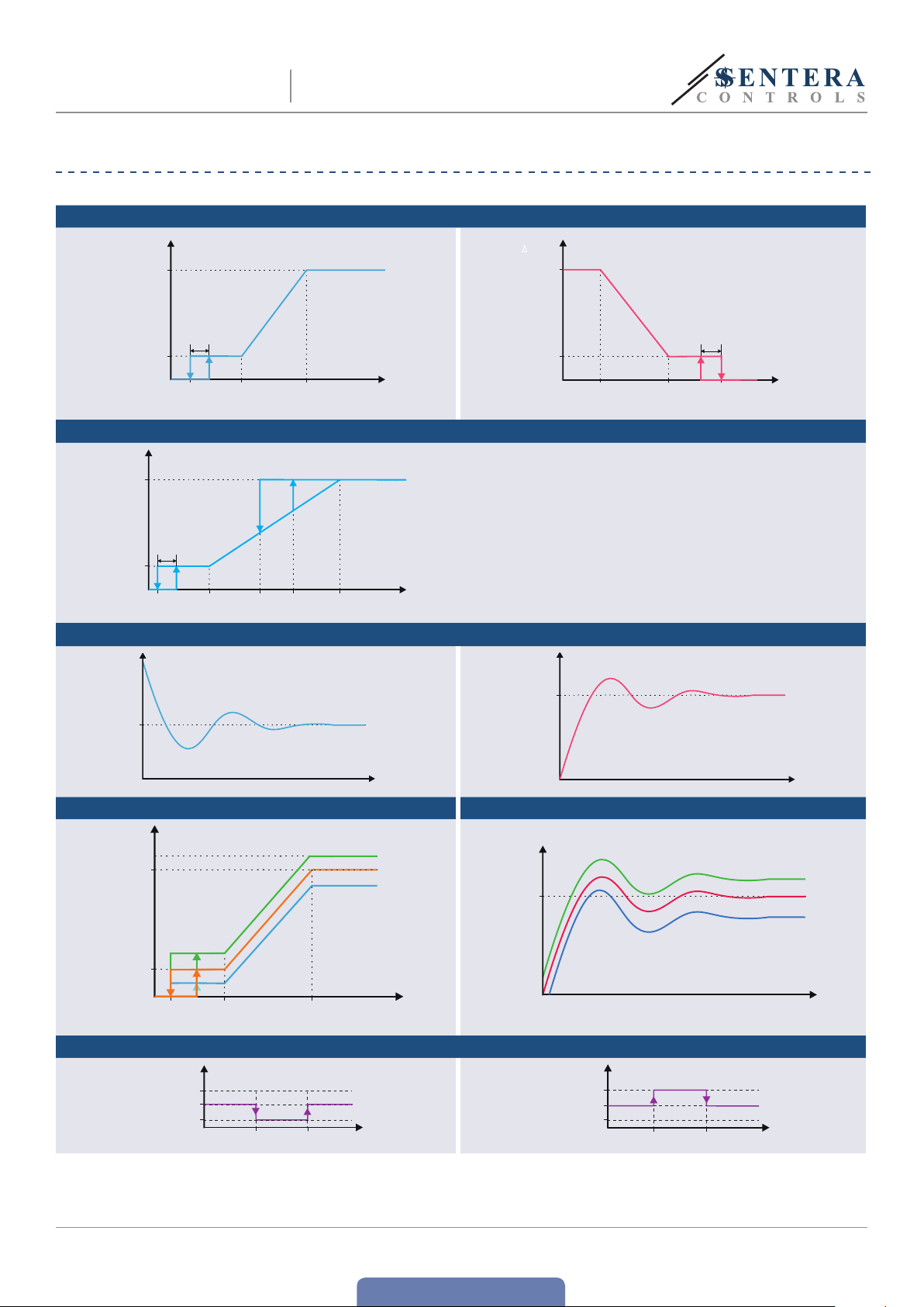
OPERATIONAL DIAGRAMS
LINEAR FUNCTION
ox, [%]
Max
Linear
(Cool , Dry, Drain
0–10 0 %)
5 %
Min
Off
level
CONTROL FUNCTION
ox, [%]
Max
Controlled output
5 %
Min
Off
level
cont rol
range
PID CONTROL
[X]
SP
Min
cont rol
range
Min
SP-
Hysteresis
PID cont rol
(Cool, Dry, Drain 0–100 %)
Max
cont rol
range
Output (normal)
Output (high priority)
SP
cont rol
range
Max
Tix/Aix,
Tix/Aix,
[x]
ox, [%]
Max
Min
Tix/Aix,
[X]
Linear (Heat, Humidify, Obtain, 100–0 %)
5 %
Off
level
SP
PID control
(Heat, Humidify, Obtain, 100–0 %)
Min
cont rol
range
Max
cont rol
range
Tix/Aix,
UNBALANCED LINEAR MODE UNBAL ANCED PID MODE
ox, [%]
Max
Ao2 output
with positive
unbalanced
coefficient
Ao1 output
Ao2 output
with negative
unbalanced
coefficient
x/Aix,
[X]
SP
Positive unbalanced
coefficient
Negative unbalanced
coefficient
Min
Off
level
Min
cont rol
range
Max
cont rol
range
Tix/Aix,
ANALOGUE OUTPUTS IN FUNCTION OF DIGITAL INPUTS
Maximum
Related value
0
MIW- MC S -1-LCD- E N - 00 0 - 20 / 07 / 2016 7 - 33
DIX remote Off
Active state
event
Inactive state
event
www.sentera.eu
Maximum
Related value
DIX maximum speed
0
Active state
event
Inactive state
event
back to the table of contents
Page 8
[x]
t, [s]
x,
[x]
t,[s]
MULTIFUNCTIONAL LOGIC
MC S -1- LC D
RELAY CONTACT FUNCTION ACTIVE STATE COM - > NO
Rcx,
[state]
COMNO
COMNC
RELAY CONTACT FUNCTION ACTIVE STATE COM -> NC
Rcx,
[state]
COMNO
COMNC
TIX/AIX function
SP-
Hysteresis
TIX/AIX function
SP-
Hysteresis
CONTROLLER
Tix/Aix,
SP
Tix/Ai
SP
MOUNTING INSTRUCTIONS IN STEPS
Before you start mounting your controller read carefully “Safety and
Precautions”. Choose a smooth surface for an installation location (a wall,
panel and etc.). Then proceed with the following mounting steps:
1. Switch off the power supply.
2. Unscrew the four screws on the front cover and open it carefully.
Rcx,
[state]
COMNO
COMNC
Rcx,
[state]
COMNO
COMNC
DIX function
Active state
event
Active state
event
Inactive state
DIX function
Inactive state
event
event
ATTENTION
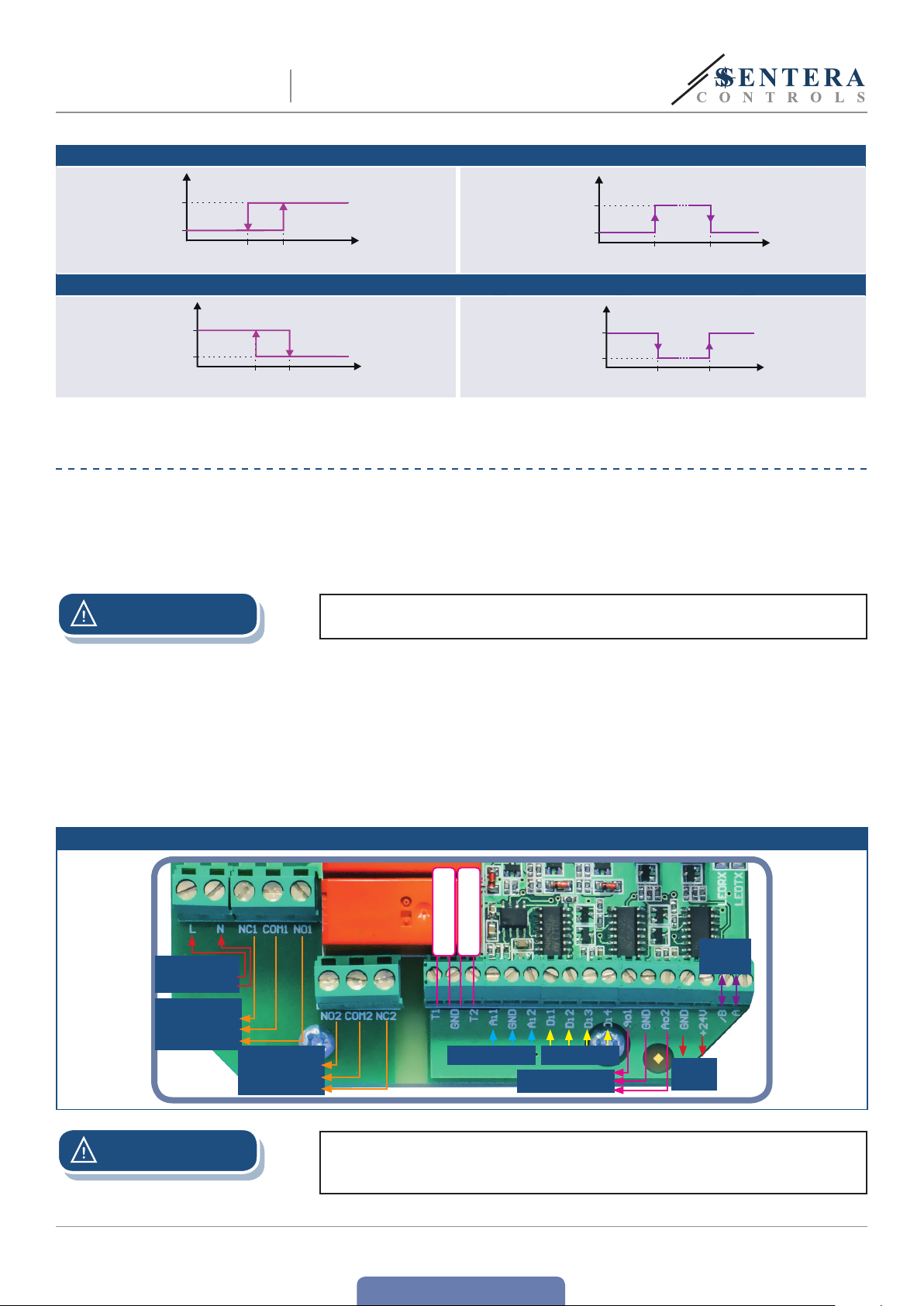
Fig. 1 Wiring and connections
Power supply
Relay contac t 1
Normally closed
Line
Neutral
Common
Normally open
Relay contac t 2
Normally closed
Normally open
Common
Make sure the flat cable, connecting the motherboard with the LCD printed circuit
board remains in place!
3. Insert the connecting cables through the cable glands of the unit.
4. Do the wiring according to the wiring diagram (see Fig. 1) using the information
from section “Wiring and connections”. Connect the controlled equipment and
the sensors (if necessary). Use cables with recommended length and type with
respect to your application. Mind the following recommendations:
►
Use shielded cables for the analogue inputs / outputs in case the cable length
is between 4 and 12 m and voltage (VDC) mode is used.
►
When the cable length exceeds 12 m, use the analogue inputs / outputs in
current (mA) mode.
PT 500 / PT1000
PT 500 / PT1000
Analogue inputs
Digital inputs
Analogue outputs
Suppl y
output
Modbus
RTU
ATTENTION
When you first use the unit make sure that the load corresponds to the default
output values. If the default values do not fit the load used, configure the unit
first, then connect the load. Improper load may cause damage to the controller.
MIW- MC S -1-LCD- E N - 00 0 - 20 / 07 / 2016 8 - 33
back to the table of contents
www.sentera.eu
Page 9
RX
MC S -1- LC D
MULTIFUNCTIONAL LOGIC
CONTROLLER
ATTENTION
Do not mix the temperature ground (GND) with other ground (GND) terminals!
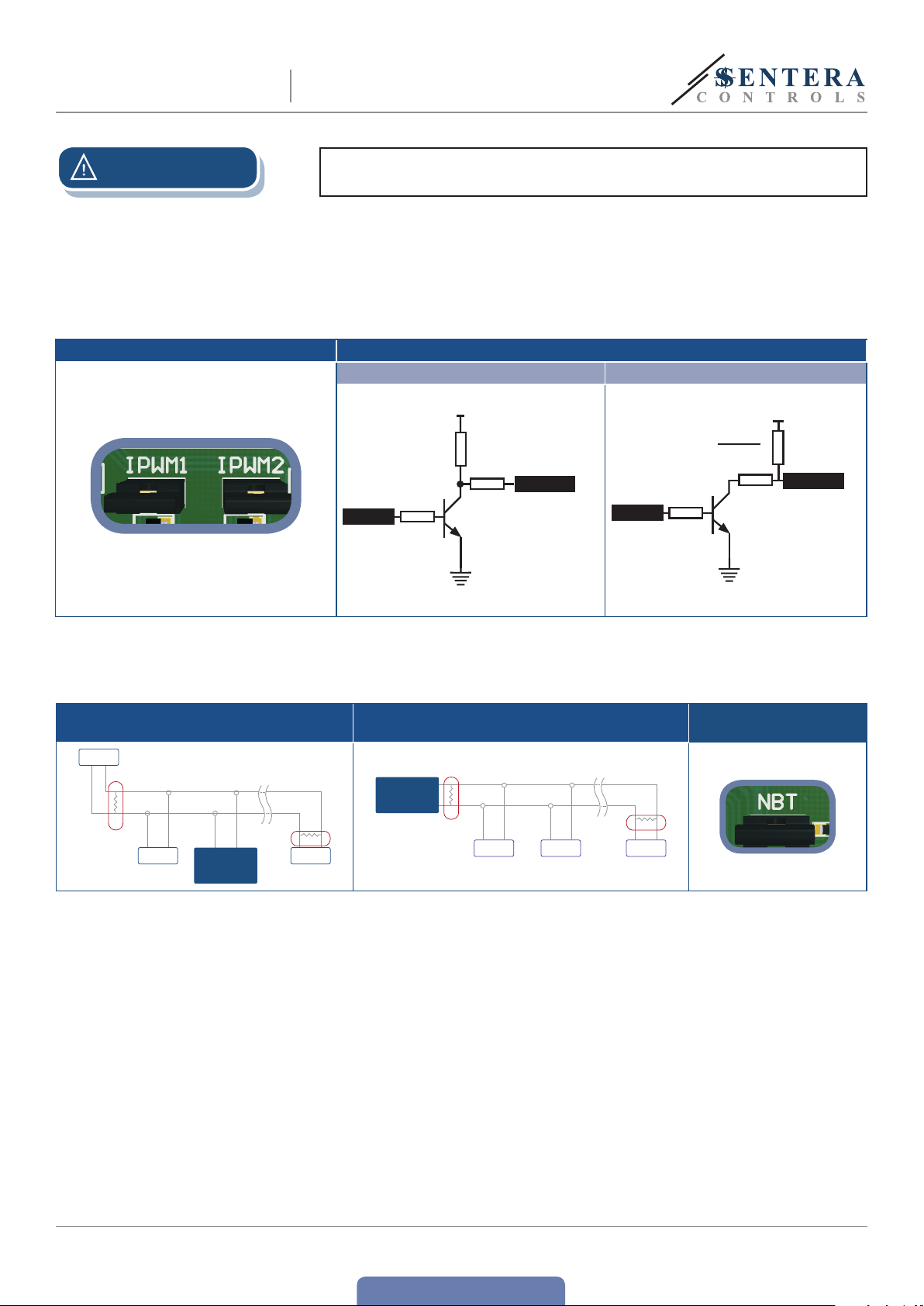
5. Customise the factory settings for the PWM outputs to the desired ones if you
are going to use a PWM output. By default the IPWM1 and IPWM2 jumpers (Fig.
2) are closed and the PWM outputs 1 and 2 are connected to an internal voltage
source of +12 VDC. See Fig. 3a Internally supplied PWM schematic. Remove
the jumpers (Fig. 2) if you need PWM open collector outputs. See Fig. 3b Open
collector schematics.
Fig. 2 PWM jumpers Fig. 3 PWM schematics
3a Internally supplied PWM schematic 3b Open collector schematic
+12 VDC
2,2 kΩ
100 Ω
Control
4,7 kΩ
BC 817
GND
PWM out
Control
4,7 kΩ
5 VDC ≤ +Vcc ≤ 24 VDC
Vcc
R
=
EXT
5 mA
100 Ω
BC 817
GND
R
EXT
PWM out
6. Check if your unit starts or terminates the network (see Example 1 and
Example2). If it does, connect the NBT resistor. Place the NBT jumper (Fig.4)
onto the pins. Otherwise leave it disconnected (default setting).
Example 1 Example 2
Slave 1
RX
NBT
NBT
Slave 2
Master
ТX
NBT
Slave n
Master
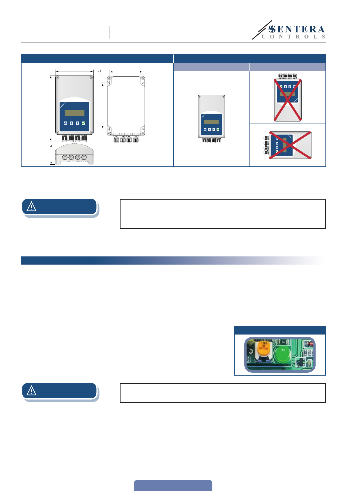
7. Fix the rear lid of the enclosure on the wall/panel by the delivered dowels and
screws. Mind the correct mounting position and unit mounting dimensions.
(SeeFig. 5 Mounting dimensions and Fig.6Mounting position.)
Fig. 4 Network bus
resistor jumper
NBT
Slave 1
Slave 2
ТX
NBT
Slave n
MIW- MC S -1-LCD- E N - 00 0 - 20 / 07 / 2016 9 - 33
www.sentera.eu
back to the table of contents
Page 10
4x
MULTIFUNCTIONAL LOGIC
MC S -1- LC D
Fig. 5 Mounting dimensions Fig.6Mounting position
115
CONTROLLER
4,50
Acceptable Not acceptable
102
201
63
ATTENTION
140
8. Close the enclosure and fix the cover.
9. Switch on the power supply.
If an AC power supply is used with any of the units in a Modbus network the
GND terminal should NOT BE CONNECTED to other units on the network or
via the CNVT‑USB‑RS485 converter. is may cause permanent damage to the
communication semiconductors and / or the computer!
10. If necessary, customize the other factory settings to the desired ones. Use
3SModbus software, 3SMonitor software or the 4-button menu and LCD display
VERIFICATION OF THE CORRECT INSTALLATION
When you first switch on the power supply, the display will illuminate and show the
time and date, Temp. °C (the default operational mode) and the active working mode
(Run or Stand-by). If this is not the case, open the enclosure and check the status of
the power on green LED. See Fig. 7 Operating indication.
■
If the LED is off, your unit is not supplied. Check the connections again.
■
If the LED is on, but the LCD display is off, check the connection of the ribbon
(flat)cable.
Fig. 7 Operation indication
ATTENTION
MIW- MC S -1-LCD- E N - 00 0 - 20 / 07 / 2016 10 - 33
Be careful when you are handling with the ribbon cable. It must not touch the
power supply block. is will damage your unit. See Fig. 8.
www.sentera.eu
back to the table of contents
Page 11

MC S -1- LC D
Fig. 8 MCS-1-LCD PCB
MULTIFUNCTIONAL LOGIC
CONTROLLER
Power supply module
Ribbon cable
e ribbon cable must not touch
the power supply module.
Check the status of the both LEDs (LEDRX and LEDTX). See Fig. 9 Modbus
communication indication. If they blink your unit has detected a Modbus network. If
they do not, check the connections again.
Fig. 9 Modbus communication indication
MIW- MC S -1-LCD- E N - 00 0 - 20 / 07 / 2016 11 - 33
back to the table of contents
www.sentera.eu
Page 12

MULTIFUNCTIONAL LOGIC
MC S -1- LC D
CONTROLLER
OPERATING INSTRUCTIONS
CONTROLLER OVERVIEW
T1
T2
Ai1
Ai2
Di1
Di2
Di3
PROBE TYPE:
PT500
PT1000
REFERENCE:
CO2
Rel.humidity
Temp
AIR quality
Diff. pressure
ACTIVE STATE :
H IGH
L OW
TYPE :
0–10 VDC
2–10 VDC
0–20 mA
4–20 mA
PWM
RANGE
FIXED or
TIMESCHEDULE
SETPOINT
FIXED or
TIMESCHEDULE
Ao1 to
MAX
Ao1 to
OFF
Ao2 to
MAX
Ao2 to
OFF
LINEAR
HEATING COOLING
HUMIDIFY DRY
OBTAIN DRAIN
CONTROL
PID
HUMIDIFY COOL
OBTAIN DRAIN
FUNCTION
0–10 VDC, 2-10 VDC
0–20 mA, 4-20 mA
PWM
0–10 VDC, 2-10 VDC
0–20 mA, 4-20 mA
PWM
Free
(Independent to Ao1)
DIGITAL OVER RULE
Balanced to Ao1
Unbalanced to Ao1
Ao1
Ao2
Relay 1
Relay 2
DI - FUNCTION
Di4
RELAY
Control
CONTROL FUNCTIONS OVERVIEW
e MCS-1-LCD controller features integrated analogue and relay outputs which can
be controlled either in one of the pre-configured modes or they can be personalised.
Its numerous different analogue, digital and temperature inputs ensure a large range
of functional control. You can choose the control function between:
LINEAR FUNCTION
Analogue outputs in linear function of the inputs
In cool mode the value of the analogue output rises linear in function of a higher
measured input value (according to the sensor(s) selected). is linear function goes
from the minimum to the maximum range of the assigned input and drops to 0 VDC
when off level is reached. e off level can be selected over the full sensor range.
In heat mode the value of the analogue output drops linear in function of a higher
measured input value.
MIW- MC S -1-LCD- E N - 00 0 - 20 / 07 / 2016 12 - 33
www.sentera.eu
back to the table of contents
Page 13

MC S -1- LC D
MULTIFUNCTIONAL LOGIC
CONTROLLER
CONTROL FUNCTION
Analogue outputs in function of the normal priority and high priority inputs
e value of an analogue output in control mode follows a linear function of the
input with normal priority until the high priority assigned input reaches its setpoint.
e value then rises to the maximum value in the selected “time to maximum”
timespan. e output stays at maximum until the high priority input value reaches
SP – hysteresis, and then it drops following the linear function of the input with
normal priority.
PID CONTROL
During the PID control the analogue output changes to keep the assigned normal
input value at its selected setpoint level. e proportional gain (Kp), integration
period (Ti) and derivation period (Td) of the PID control are free configurable to set
the required slope, gain or magnitude.
e implemented autotune function calculates the parameters automatically
according to the system.
ANALOGUE OUTPUTS IN FUNCTION OF THE DIGITAL INPUTS
e analogue outputs can individually correspond to the state of the digital input.
When a digital input with remote off function becomes ‘active’, the related analogue
output drops to 0 and goes back to the current function value (Linear, Control or PID)
when it becomes ‘inactive’. When a digital input with ‘maximum output’ func tion
becomes ‘active’, the related analogue output rises to maximum and goes back to
the current function value (Linear, Control or PID) when it becomes ‘inactive’. All the
digital inputs have priority to all the other inputs (Ai1, Ai2, T1 and T2).
FREE
e second analogue output Ao2 is independent from the first analogue output Ao1.
BALANCED
e value of the second analogue output Ao2 follows the value of the first output Ao1.
UNBALANCED
In unbalanced mode the value of the se cond analogue ou tput Ao2 follows the func tion
of the first output Ao1 according to the set offset values. See the operational
diagrams with positive and negative unbalanced (offset) coefficient.
RELAY CONTACT FUNCTION
Depending on the pre-selected active state of a relay, the relay contact switches
open or closed at the previously set setpoint of the assigned analogue or temperature
input, and switches back (closed or open) at the SP - hysteresis value.
In case there is an assigned digital input for relay switching, the relay contact
switches open or closed at the event of active state and switches back (closed or
open) when the state changes to inactive.
MIW- MC S -1-LCD- E N - 00 0 - 20 / 07 / 2016 13 - 33
back to the table of contents
www.sentera.eu
Page 14

MULTIFUNCTIONAL LOGIC
MC S -1- LC D
CONTROLLER
PARAMETERS AND DEFAULT SETTINGS
GENERAL
Parameter Default value
Temperature input 1 and 2 (T1 & T2) Input state In use
Sensor range -30—70 °C
Control range 0—40 °C
Off level -10 °C
Setpoint 20 °C
Hysteresis 2 °C
Units Celsius
Calibration Stand-by
Analogue input 1 and 2 (Ai1 & Ai2) Input type Not in use
Sensor range 0—10,0 VDC
Measured quantity Relative humidity
Reference sensor range 20—80 % rH
Control range 20—80 % rH
Off level 20 % rH
Setpoint 50 % rH
Hysteresis 6 % rH
Free units Empty
Digital input 1, 2, 3 and 4 (Di1, Di2, Di3 & Di4) Function Not in use
Active state Low
Analogue output 1 and 2 (Ao1 & Ao2) Output type 0—10,0 VDC
Output function Linear
Output mode Cool
Minimum value 0 %
Maximum value 100 %
Time to maximum 60 s
Kp value 1,0 gain
Ti value 10 s
Td value 1 s
Autotune PID control Stand-by
Analogue output 1 (Ao1) Assigned normal input Temperature input 1 (T1)
Assigned high priority input Analogue input 2 (Ai2)
Analogue output 2 (Ao2) Assigned normal input Temperature input 2 (T2)
Assigned high priority input Analogue input 1 (Ai1)
Analogue output relation Free
Unbalance coefficient 0 %
Relay contacts 1 and 2 (Rc1 & Rc2) Assigned input(s) Not in use
Functionality Device functionality Temperature Cool
Passwords Installer password 0000
User password 0000
MIW- MC S -1-LCD- E N - 00 0 - 20 / 07 / 2016 14 - 33
back to the table of contents
www.sentera.eu
Page 15

BOOT
MODE
J4
RUN
MULTIFUNCTIONAL LOGIC
MC S -1- LC D
Parameter Default value
Scheduling Scheduled number of run periods 1
Scheduled run period 1 duration 8:30 - 17:00
Scheduled run period 2 duration --:-- - --:--
Scheduled run period 3 duration --:-- - --:--
Scheduled run period 4 duration --:-- - --:--
Scheduled run period 1 days of week Monday, Tuesday, Wednesday, ursday, Friday
Scheduled standby period 1 duration dd mmm yyyy - dd mmm yyyy
Scheduled standby period 2 duration dd mmm yyyy - dd mmm yyyy
Scheduled standby period 3 duration dd mmm yyyy - dd mmm yyyy
Scheduled standby period 4 duration dd mmm yyyy - dd mmm yyyy
CONTROLLER
CONFIGURING THE PARAMETERS
e default parameters can be modified by using either one of predefined userfriendly templates or by customising them freely.
ATTENTION
NOTE
e mode selector (Fig. 10) should always be in run mode except for firmware
updates.
Fig. 10 Mode selector
e USB interface allows LCD display and control board firmware updates. To
update contact the technical support.
MIW- MC S -1-LCD- E N - 00 0 - 20 / 07 / 2016 15 - 33
www.sentera.eu
back to the table of contents
Page 16

MULTIFUNCTIONAL LOGIC
MC S -1- LC D
CONTROLLER
USING PREDEFINED TEMPLATES
See table Tabl e below to know about the available templates that pre-define the
device functionality.
Device functionality
Predefined templates
Parameters
Control range (T1) 0—40°C 0—40°C N/A N/A N/A N/A 0—40°C 0—40°C 0—40°C
Off level (T1) -10°C 40°C N/A N/A N/A N/A -10°C -10 ° C -10° C
Setpoint (T1) N/A N/A N/A N/A N/A N/A N/A 20°C N/A
Control range (T2) 0—40°C 0—40°C N/A N/A N/A N/A N/A N/A 0—40°C
Off level (T2) 0°C 40°C N/A N/A N/A N/A N/A N/A -10 °C
Setpoint (T2) N/A N/A N/A N/A N/A N/A N/A N/A N/A
Control range (Ail) N/A N/A 20—80 % rH 0—2.000 ppm 0—2.000 ppm 0—2.000 Pa 0—2.000 ppm 0—2.000 Pa 0—10.000
Off level (Ail) N/A N/A 20 % rH 0 ppm 0 ppm 0 Pa 0 ppm 0 Pa N/A
Setpoint (Ail) N/A N/A N/A N/A N/A N/A 1000 ppm N/A 5.000 units
Control range
(Ai2)
Off level (Ai2) N/A N/A N/A N/A N/A N/A N /A N/A N/A
Setpoint (Ai2) N/A N/A N/A N/A N/A N/A N /A N/A 5.000 units
Analog output
function (Aol)
Analog output
mode (Aol)
Assigned normal
input (Aol)
Assigned high
priority input (Aol)
Analog output
function (Ao2)
Analog output
mode (Ao2)
Assigned normal
input (Ao2)
Assigned high
priority input
(Ao2)
Temperature
cool
Temperature
heat
N/A N/A N /A N/A N/A N /A N/A N/A 0—10.000
Linear Linear Linear Linear Linear Linear Controlled Controlled Controlled
Cool Heat 0—10 VD C 0 —10 VD C 0—10 V DC 10— 0 VDC N/A N/A N/A
T1 T1 A i1 Ai1 A i1 Ai1 T1 Ai1 T1
N/A N/A N /A N/A N/A N /A Ai1 T1 Ai1
Linear Linear N/A N/A N/A N/A Linear Linear Controlled
Cool Heat N/A N/A N/A N/A 0 —10 VD C Cool N/A
T2 T2 N/A N/A N/A N/A Ai1 T1 T2
N/A N/A N /A N/A N/A N /A N/A N/A Ai2
Relative
humidity
CO
2
Air quality Differential
pressure
Temperature
and CO
2
Differential
pressure and
temperature
Free
units
units
MIW- MC S -1-LCD- E N - 00 0 - 20 / 07 / 2016 16 - 33
www.sentera.eu
back to the table of contents
Page 17

MC S -1- LC D
CUSTOMISING THE SETTINGS
MULTIFUNCTIONAL LOGIC
CONTROLLER
ere are 3 possible ways to customize the default parameters:
■
using 3SMonitor software
■
using 3SModbus software, and
■
with the help of the 4-buton interface
3SMONITOR SOFTWARE
3SMonitor application is a free Sentera software. You can download it from our
website at http://www.senteracontrols.com/3smodbus/Setup3SM.msi
ATTENTION
Before you download it, make the connections carefully. Connect a USB cable
between connector J1 (Fig. 11) and the computer USB port.
Fig. 11 USB connector J1
e USB connector J4 shown in F ig. 12 is for firmware updates only.
Fig. 12 USB connector J4
MIW- MC S -1-LCD- E N - 00 0 - 20 / 07 / 2016 17 - 33
back to the table of contents
www.sentera.eu
Page 18

MC S -1- LC D
MULTIFUNCTIONAL LOGIC
CONTROLLER
When you run the 3SMonitor application, the home screen shown in Fig. 13 will
appear on your screen. Installer access level provides full control over the device
inputs and outputs configuration, time schedule and firmware update. e user
access level provides only monitoring, scheduling and setting time and date. If you
log in as Installer, you can choose between setup wizard and monitoring (Fig. 14).
Fig. 13 3SMonitor home screen
NOTE
e password box is not available when password is removed.
Fig. 14 Wizard / Monitoring screen
For further information about parameter configuring refer to the chapter “Main
menu structure”.
3SMODBUS SOFTWARE
3SModbus is a free application for Windows. You can download it from our website
at http://www.senteracontrols.com/3smodbus/3smodbus.exe
MIW- MC S -1-LCD- E N - 00 0 - 20 / 07 / 2016 18 - 33
back to the table of contents
www.sentera.eu
Page 19

MC S -1- LC D
MULTIFUNCTIONAL LOGIC
CONTROLLER
Before you download it, make the connec tions carefully. Connect A and /B terminals
with A and /B of a CNVT-USB-RS485 converter (Fig. 15).
Fig. 15 CNVT-USB-RS485 converter
ATTENTION
Do NOT connect the GND signal of the CNVT‑USB‑RS485 converter! (See section
“Wiring and Connections”.) is may damage the computer’s USB port.
When you run the 3SModbus application, the home screen shown in Fig. 16 will
appear on your screen.
Fig. 16 3SMоdbus home screen
For parameter settings refer to Chapter “Modbus register maps”.
4-BUTON KEYBOARD INTERFACE
Fig. 17 LCD display home screen
To configure the MCS-1-LCD, use the 4-button interface and LCD display following
the menu structure. (See chapter “Main menu structure”.). For the parameter
default values, please refer to “Modbus register maps” chapter.
MIW- MC S -1-LCD- E N - 00 0 - 20 / 07 / 2016 19 - 33
back to the table of contents
www.sentera.eu
Page 20

6
7
8
9
1
2
1
345
MC S -1- LC D
MAIN MENU STRUCTURE
MULTIFUNCTIONAL LOGIC
CONTROLLER
NOTE
Home screen
User or installer
password prompt
e framed menu is only available
User
if logged in as installer
Output screen
Schedule
installer settings
To configure the MCS‑1‑LCD using the 4‑button interface and LCD display, you can
follow the next menu structure. e possible parameter values and their default
values can be found in the table “Modbus register maps”.
Temperature
inputs screen
Device
functionality
Analogue inputs
Digital inputs
Analogue outputs
Analogue inputs
screen
Digital inputs
Time and date
setup
Run periods
Run days
Standby periods
Run per iods
parameters
screen
Change installer
password
Remove installer
password
Reset installer
password
Change user
password
Remove user
password
Reset user
password
Installer command
prompt
User or installer
password prompt
Relay contacts
installer password
options
Bootloader
Reset to def ault
Clear schedule
User password
options
MIW- MC S -1-LCD- E N - 00 0 - 20 / 07 / 2016 20 - 33
back to the table of contents
www.sentera.eu
Page 21

1
MC S -1- LC D
MULTIFUNCTIONAL LOGIC
CONTROLLER
DEVICE FUNCTIONALITY SELECTION
Temperature cool
Temperature heat
Relative humidity
CO
2
Air quality
Differential pressure
Temperature and CO
Differential pressure and
temperature
Free
2
MIW- MC S -1-LCD- E N - 00 0 - 20 / 07 / 2016 21 - 33
back to the table of contents
www.sentera.eu
Page 22

2
MC S -1- LC D
MULTIFUNCTIONAL LOGIC
CONTROLLER
ANALOGUE INPUTS SETUP
T1
T2
Ai1
T1 state Not in use
T1 uni ts In use
Calibration
rH
AQ
CO
DP
Not in use
In use
2
T2state
T2 uni ts
Calibration
T1 state
Measured
quantity
Celsius
Fahrenheit
Celsius
Fahrenheit
Set range reference
Set range reference
Set range reference
Set range reference
Start callibration
Rese t to fac tor y
callibration
Start callibration
Rese t to fac tor y
callibration
Not in use
0—10 VDC
0—20 m A
2—10 VD C
4—20 m A
PWM
Celsius
Fahrenheit
Ai2 Input type
Celsius
Units
Set range reference
Measured
quantity
Units
Free
Tem p
rH
AQ
CO
DP
Free
Tem p
Enter units
Set range reference
Not in use
Set range reference
Set range reference
2
Set range reference
Set range reference
Enter units
Set range reference
0—10 VDC
0—20 m A
2—10 VD C
4—20 m A
PWM
Fahrenheit
MIW- MC S -1-LCD- E N - 00 0 - 20 / 07 / 2016 22 - 33
Set range reference
www.sentera.eu
back to the table of contents
Page 23

3
MC S -1- LC D
MULTIFUNCTIONAL LOGIC
CONTROLLER
DIGITAL INPUTS SETUP
Di1
Di2
Di3
Di4
Assign function
Active state
Backlight
High
Low
On
Off
Assign function
Active state
Backlight
Not in us e
Remot e off Ao1
Maxim um output Ao1
Mode se lect ion Ao1
Remot e off Ao2
High
Low
On
Off
Not in us e
Remot e off Ao1
Maxim um output Ao1
Mode se lect ion Ao1
Remot e off Ao2
Maxim um output Ao 2
Mode se lect ion Ao2
Relay control
Assign function
Active state
Backlight
Assign function
Active state
Backlight
High
Low
On
Off
High
Low
On
Off
Not in us e
Remot e off Ao1
Maxim um output A o1
Mode se lect ion Ao1
Remot e off Ao2
Maxim um output A o2
Mode se lect ion Ao2
Relay control
Not in us e
Remot e off Ao1
Maxim um output A o1
Mode se lect ion Ao1
Remot e off Ao2
Maxim um output Ao 2
Mode se lect ion Ao2
Relay control
Maxim um output A o2
Mode se lect ion Ao2
Relay control
MIW- MC S -1-LCD- E N - 00 0 - 20 / 07 / 2016 23 - 33
www.sentera.eu
back to the table of contents
Page 24

4
MC S -1- LC D
MULTIFUNCTIONAL LOGIC
CONTROLLER
ANALOGUE OUTPUTS SETUP
If Controlled function
typ e is selec ted
If Controlled function
typ e is selec ted
If PID fu nction
is selected
If PID fu nction
is selected
If PID fu nction
is selected
If PID fu nction
is selected
Set ou tput t ype
Set relation
Set mi n and max
output value
Assi gn norm al
T/Ai
Assi gn high
priority T/Ai
Time to maximum
Kp val ue
Ti val ue
Td va lue
Autotune
Ao1
Ao2
Balanced
Unbalanced
Free
Not in us e
0—10 VDC
2—10 VD C
0—20 m A
4—20 m A
PWM
Coefficient
Set funct ion ty pe Linear
If linear fun ctio n
typ e is selec ted
If con troll ed
func tion type is
selected
If con troll ed
func tion type is
selected
If PID fu nct ion is
selected
If PID fu nct ion is
selected
If PID fu nct ion is
selected
If PID fu nct ion is
selected
Controlled
PID
Set ou tput t ype
Set relation
Set mi n and max
output value
Assi gn norm al
T/Ai
Assi gn high
priority T/Ai
Time to maximum
Kp val ue
Ti val ue
Td va lue
Autotune
Heat
Cool
Heat
Cool
Not in us e
0—10 VDC
2—10 VD C
0—20 m A
4—20 m A
PWM
Linear
Controlled
PID
Heat
Cool
Heat
Cool
MIW- MC S -1-LCD- E N - 00 0 - 20 / 07 / 2016 24 - 33
back to the table of contents
www.sentera.eu
Page 25

5
MC S -1- LC D
MULTIFUNCTIONAL LOGIC
CONTROLLER
RELAY CONTACT SETUP
Rc1
Rc2
Assign input
Assign input Not in use
T1
T2
Ai1
Ai2
Di1
Not in use
T1
T2
Ai1
Ai2
Di1
Di2
Di3
Di2
Di3
Di4
Only active or related
inputs are listed
Di4
Only active or related
inputs are listed
MIW- MC S -1-LCD- E N - 00 0 - 20 / 07 / 2016 25 - 33
back to the table of contents
www.sentera.eu
Page 26

MC S -1- LC D
MULTIFUNCTIONAL LOGIC
CONTROLLER
SCHEDULE
Run days
6
Peri od 1 Monday Enable
Peri od 2
Peri od 3
Peri od 4
Only active periods are
list ed. e submenus f or
all periods are identical
Tuesday
Wednesday
ursday
Friday
Saturday
Sunday
e subm enus fo r all
periods are identical
Disable
Run periods Standby periods
7
Peri od 1
Peri od 2
Peri od 3
Peri od 4 Set
Set
Set
Set
8
Peri od 1
Peri od 2
Peri od 3
Peri od 4 Set
Set
Set
Set
MIW- MC S -1-LCD- E N - 00 0 - 20 / 07 / 2016 26 - 33
www.sentera.eu
back to the table of contents
Page 27

MC S -1- LC D
MULTIFUNCTIONAL LOGIC
CONTROLLER
RUN SETTINGS
9
Peri od 1
Peri od 2
Peri od 3
Peri od 4
Only active period are
list ed. e submenus
for all perio ds are
identical
Control range
Off lev el
If assi gned in linear
or primary controlled
analogue output
T1
T2
Ai1
Ai2
Only active or related
inpu ts are listed
Setpoint
Hysteresis
If assi gned in
secondary controlled
analogue output
Control range
Off lev el
If assi gned in linear
or primary controlled
analogue output
Setpoint
If assi gned in r elay
cont acts or in PID
controlled analogue
output
Setpoint
Hysteresis
If assi gned in
secondary controlled
analogue output
Control range
Off lev el
If assi gned in linear
or primary controlled
analogue output
Control range
Off lev el
If assi gned in linear
or primary controlled
analogue output
Setpoint
If assi gned in r elay
cont acts or in PID
controlled analogue
output
Setpoint
Hysteresis
If assi gned in
secondary controlled
analogue output
Setpoint
Hysteresis
If assi gned in
secondary controlled
analogue output
Setpoint
If assi gned in r elay
cont acts or in PID
controlled analogue
output
Setpoint
If assi gned in r elay
cont acts or in PID
controlled analogue
output
MIW- MC S -1-LCD- E N - 00 0 - 20 / 07 / 2016 27 - 33
www.sentera.eu
back to the table of contents
Page 28

MULTIFUNCTIONAL LOGIC
MC S -1- LC D
CONTROLLER
MODBUS REGISTER MAPS
INPUT REGISTERS
Data type Description Data Values
1 Temperature level (T1) signed int. Temperature level (T1) -300—700 500 = 50,0°C
2 Temperature level (T2) signed int. Temperature level (T2) -300—700 500 = 50,0°C
3 Analogue input level (Ai1) signed int. Analogue input level (Ai1) 0—1.000
4 Analogue input level (Ai2) t tsigned int. Analogue input level (Ai2) 0—1.000
5 Digital input s tatus (Di1) signed int. Digital input status (Di1) - act ive / in active 0—1
6 Digital input status (Di2) signed int. Digital input s tatus (Di2) - act ive / inactive 0—1
7 Digital input s tatus (Di3) signed int. Digital input s tatus (Di3) - act ive / in active 0—1
8 Digital input s tatus (Di4) signed int. Digital input s tatus (Di 4) - active / inact ive 0—1
9-10 Reserved, re turns 0
11 Anal ogue ou tput value ( Ao1) signed int. Value of t he analogue outpu t (Ao1) - 0—10 VDC 0—1.000
12 Analogue out put va lue (Ao2) signed int. Value of th e analo gue output (Ao2) - 0—10 VDC 0—1.000
13 Relay 1 st atus signed int.
14 Relay 2 status signed int.
15 Current year unsigned int. Current year 2000—2099
16 Current month unsigned int. Current month 1—12
17 Current day unsigned int. Current day 1—31
18 Current hour unsigned int. Current hour 0—23
19 Current minutes unsigned int. Current minutes 0—59
20 Current seconds unsigned int. Current seconds 0—59
21 Temperature input sensor range (T1) signed int.
22 Temperature input control range (T1) signed int.
23 Off level for t emper atur e inpu t (T1) signed int. S elec ted off level f or temp erat ure input ( T1) -200—600 500 = 50,0 ° C
24 Setpoint for temperature input (T1) signed int. Selected setpoint for temperature input (T1) -200—600 500 = 50,0 °C
25 Hys tere sis for temperature inpu t (T 1) signed int. Se lected hys tere sis for temperature input (T 1)
26 Sens or type (T 1) unsigned int. Current sensor t ype co nnec ted to t he input (T1) 0—1
27 Temperature input sensor range (T2) signed int.
28 Temperature input control range (T2) signed int.
29 Off level for temper atur e inpu t (T2) signed int. S elec ted off level for temperat ure input ( T2) -200—600 500 = 50,0 °C
30 Setpoint for temperature input (T2) signed int. Selected setpoint for temperature input (T2) -200—600 500 = 50,0 ° C
31 Hy ster esis for temperature inp ut ( T2) signed int. Selec ted hy ster esis f or temp erat ure input ( T2)
32 Sensor type (T 2) unsigned int. Current sensor t ype co nnec ted to t he input (T2) 0—1
33 Analogue input sensor range (Ai1) unsigned int.
34 Analogue input control range (Ai1) unsigned int.
Relay 1 s tatus. When it i s NO, the contact between
COM1 and NO1 is closed.
Relay 2 s tatus. When it i s NO, the contact between
COM1 and NO1 is closed.
Selected temperature input sensor range (T1),
calculated from holding registers values
Selected temperature input control range (T1),
calculated from holding registers values
Selected temperature input sensor range (T2),
calculated from holding registers values
Selected temperature input control range (T2),
calculated from holding registers values
Selected analogue input sensor range (Ai1),
calculated from holding registers values
Selected analogue input control range (Ai1),
calculated from holding registers values
0—1
0—1
-300—700 0—500 = 0—50,0 °C
-300—700 0—500 = 0 —50,0 °C
5, 10, 15,
20, 25, 30
-300—700 0—500 = 0—50,0 °C
-300—700 0—500 = 0 —50,0 °C
5, 10, 15,
20, 25, 30
0—1.000 0—1.000 0 —10 V DC
0—1.000 0—1.000 0 —10 V DC
300 =
300 =
300 =
300 =
0 =
1 =
0 =
1 =
0 =
1 =
0 =
1 =
300 =
300 =
300 =
300 =
0 =
1 =
0 =
1 =
1 =
12 =
5 =
10 =
15 =
20 =
25 =
30 =
0 =
1 =
5 =
10 =
15 =
20 =
25 =
30 =
0 =
1 =
3,0 VDC ( 30 %)
6 mA (30 %)
3,0 VDC ( 30 %)
6 mA (30 %)
inactive
inactive
inactive
inactive
3,0 VDC ( 30 %)
6 mA (30 %)
3,0 VDC ( 30 %)
6 mA (30 %)
January
December
PT500
PT1000
PT500
PT1000
active
active
active
active
NC
NO
NC
NO
0,5 °C
1,0 ° C
1,5 ° C
2,0 °C
2,5 °C
3,0 °C
0,5 °C
1,0 ° C
1,5 ° C
2,0 °C
2,5 °C
3,0 °C
MIW- MC S -1-LCD- E N - 00 0 - 20 / 07 / 2016 28 - 33
www.sentera.eu
back to the table of contents
Page 29

MULTIFUNCTIONAL LOGIC
MC S -1- LC D
INPUT REGISTERS
35 Off level fo r analo gue input (Ai1) unsigned int. Selecte d off level for an alogu e input (Ai1) 0—950
36 Setpoint for analogue input (Ai1) unsigned int. Selec ted setpoint for analogue input (Ai1) 200—1.000
37 Hysteresis fo r analogue input (Ai1) unsigned int. Selected hys tere sis for analogue inpu t (Ai1)
38 Reserved, re turn s 0
39 Analogue input sensor range (Ai2) unsigned int.
40 Analogue input control range (Ai2) unsigned int.
41 Off level f or analogue input (A i2) unsigned int. Select ed off level for a nalog ue inpu t (Ai2) 0—950
42 Setpoint for analogue input (Ai2) unsigned int. Selected setpoint for analogue input (Ai2) 200—1.000
43 Hy ster esis f or analogue input (A i2) unsigned int. S elec ted hy ster esis for analogue input (A i2)
44-46 Reserved , retu rns 0
HOLDING REGISTERS
Data type Description Data Default Values
1 Device slave address unsigned int. Modbus device address 1—247 1
2 Modbus baud rate unsigned int. Modbus communication baud rate 1— 4 2
3 Modbus parity unsigned int. Parity check mode 0—2 1
4 Device type unsigned int. Device type (Read only )
5 HW version unsigned int.
6 FW version unsigned int.
7 Operating mode unsigned int.
8 Output override unsigned int.
9 Device functionality unsigned int. Selec ts the operational mode 0—8 0
11 Tempera ture inpu t state (T 1) unsigned int.
14 Minimum control range (T1) signed int. Minimum control range value for T1 -300—700 0 0 = 0 °C
15 Maximum control range (T1) signed int. Maximum control range value for T1 -300—700 400 400 = 40 °C
16
17
18
19
20 Temperature input state (T2) unsigned int.
23 Minimum control range (T2) signed int. Minimum control range value for T2 -300—700 0 0 = 0 °C
24 Maximum control range (T2) signed int. Maximum control range value for T2 -300—700 400 400 = 40 °C
25
26
Off level for temperature
inpu t (T1)
Setpoint for temperature
inpu t (T1)
Hysteresis for temperature
inpu t (T1)
Calibration of temperature
inpu t (T1)
Off level for temperature
inpu t (T2)
Setpoint for temperature
inpu t (T2)
signed int. O ff level f or temperature input T 1 -200—600 -100 -100 = -10 ° C
signed int.
signed int.
unsigned int.
signed int. O ff level f or temperature input T 2 -200—600 -100 -100 = -10 ° C
signed int.
CONTROLLER
Data type Description Data Values
50, 100,
150 , 2 00
Selected analogue input sensor range (Ai2),
calculated from holding registers values
Selected analogue input control range (Ai2),
calculated from holding registers values
Hard ware version of the device (Read
only)
Firmware versi on of th e device (Read
only)
Enables Modbus control and disables the
jumpers
Enables the direct control over the
outputs. Always settable. Active only if
holding register 7 is set to 1.
Enables or disables the temperature input
(T 1)
Setpoint f or temperature in put T1. Used
only if assigned to a controlled analogue
output, PID or relay output.
Hysteres is for temper atur e input T1.
Used only i f assigne d to controlled
analogue output.
Star t or reset factor y cal ibra tion o f
temperature input T1
Enables or disables the temperature input
(T2)
Setpoint f or temperature in put T2. Used
only if assigned to a controlled analogue
output, PID or relay output.
MCS-1-LCD = 2003
XXXX 0 x 0160 = HW version 1.60
XXXX 0 x 0120 = F W version 1.20
0—1 0
0—1 0
0—1 1
-200—600 200 200 = 20 °C
5, 10, 15, 20,
25, 30
0—2 0
0—1 1
-200—600 200 200 = 20 °C
0—1.000 0—1.000 0 —10 V DC
0—1.000 0—1.000 0 —10 V DC
50, 100,
150 , 2 00
1 =
2 =
3 =
4 =
0 =
1 =
2 =
0 =
1 =
0 =
1 =
0 = Temperature cool
1 = Temperature heat
2 = Relative humidity
3 = CO
4 = Air quality
5 = Differential pressure
6 = Temperature and CO
7 =
8 = Free
0 =
1 =
20 20 = 2,0 °C
0 =
1 =
2 =
0 =
1 =
300 =
300 =
300 =
300 =
50 =
0,5 VDC = 1 m A (0,5 %)
100 =
1,0 VDC = 2 mA (10 %)
150 =
1,5 VDC = 3 mA (15 %)
200 =
2,0 VDC = 4 m A (20 %)
300 =
300 =
300 =
300 =
50 =
0,5 VDC = 1 m A (0,5 %)
100 =
1,0 VDC = 2 mA (10 %)
150 =
1,5 VDC = 3 mA (15 %)
200 =
2,0 VDC = 4 m A (20 %)
Differential pressure and
Start user calibration
Reset factory calibration
3,0 VDC ( 30 %)
6 mA (30 %)
3,0 VDC ( 30 %)
6 mA (30 %)
3,0 VDC ( 30 %)
6 mA (30 %)
3,0 VDC ( 30 %)
6 mA (30 %)
19.200
38.400
57.600
Standalone mode
Modbus mode
Disabled
Enabled
temperature
Not in use
Stand-by
Not in use
9.600
8N1
8E1
8O1
In use
In use
2
2
MIW- MC S -1-LCD- E N - 00 0 - 20 / 07 / 2016 29 - 33
www.sentera.eu
back to the table of contents
Page 30

MULTIFUNCTIONAL LOGIC
MC S -1- LC D
HOLDING REGISTERS
Data type Description Data Default Values
27
28
29 Analogue inpu t type (Ai1) unsigned int.
32 Minimum control range (Ai1) signed int. Minimum control range value for Ai1 0—1.000 0 300 = 3,0 VDC = 6,0 mA (3 0 %)
33 Maximum control range (Ai1) signed int. Maximum control range value for Ai1 0—1.000 1.000 1.000 = 10,0 VDC = 20,0 mA (100 %)
34
35
36
37 Reserved , retu rns 0
38 Analogue input t ype (Ai2 ) unsigned int.
41 Minimum control range (Ai2) signed int. Minimum control range value for Ai2 0—1.000 0 300 = 3,0 VDC = 6,0 mA ( 30 %)
42 Maximum control range (Ai2) signed int. Maximum control range value for Ai2 0—1.000 1.000 1.000 = 10,0 VDC = 20, 0 mA (100 %)
43
44
45
46 Reser ved, retur ns 0
47 Digital input function (Di1) unsigned int.
48 Digital input ac tive state (D i1) unsigned int. S elec ts active sta te for digital inp ut Di1 0—1 0
49 Digital input function (Di2) unsigned int.
50
51 Digital input func tion (Di3) unsigned int.
52
53 Digital input function (Di4) unsigned int.
54
Hysteresis for temperature
inpu t (T2)
Calibration of temperature
inpu t (T2)
Off lev el for analogue inpu t
(Ai1)
Setpoint for analogue input
(Ai1)
Hysteresis for analogue input
(Ai1)
Off lev el for analogue inpu t
(Ai2)
Setpoint for analogue input
(Ai2)
Hysteresis for analogue input
(Ai2)
Digi tal inp ut ac tive s tate
(Di2)
Digi tal inp ut ac tive s tate
(Di3)
Digi tal inp ut ac tive s tate
(Di4)
signed int.
unsigned int.
signed int. O ff level f or analogue input A i1 0—950 0 300 = 3,0 V DC = 6,0 mA (30 %)
signed int.
signed int.
signed int. O ff level f or analogue input A i2 0—950 0 300 = 3,0 V DC = 6,0 mA (30 %)
signed int.
signed int.
unsigned int. Sele cts a cti ve state for digit al inpu t Di2 0 —1 0
unsigned int. Sele cts a cti ve state for digit al inpu t Di3 0 —1 0
unsigned int. Sele cts a cti ve state for digit al inpu t Di4 0 —1 0
CONTROLLER
Hysteres is for temper atur e input T2.
Used only i f assigne d to controlled
analogue output.
Star t or reset factor y cal ibra tion o f
temperature input T2
Disables or selects the analogue input
typ e for Ai1
Set point fo r analogue i nput Ai1. Used only
if assigned to controlled analogue output,
PID or relay output.
Hysteres is for analogue input Ai1. Used
only if assigned to controlled analogue
output.
Disables or selects the analogue input
typ e for Ai2
Setpoint f or analogue in put Ai2. Used
only if assigned to controlled analogue
output, PID or relay output.
Hysteres is for analogue input Ai2. Used
only if assigned to controlled analogue
output.
Disables or selects a digital input function
for Di1
Disables or selec ts a digital input
function for Di2
Disables or selec ts a digital input
function for Di3
Disables or selec ts a digital input
function for Di4
5, 10, 15, 20,
25, 30
0—2 0
0—5 1
200—1.000 500 500 = 5,0 V DC = 10,0 mA (50 %)
50, 100, 150, 200 10 0 100 = 1,0 VDC = 2,0 mA (10 %)
0—5 1
200—1.000 500 500 = 5,0 V DC = 10,0 mA (50 %)
50, 100, 150, 200 10 0 100 = 1,0 VDC = 2,0 mA (10 %)
0—7 0
0—7 0
0—7 0
0—7 0
20 20 = 2,0 °C
0 =
1 =
2 =
0 =
1 =
2 =
3 =
4 =
5 =
0 =
1 =
2 =
3 =
4 =
5 =
0 =
1 =
2 =
3 =
4 =
5 =
6 =
7 =
0 =
1 =
0 =
1 =
2 =
3 =
4 =
5 =
6 =
7 =
0 =
1 =
0 =
1 =
2 =
3 =
4 =
5 =
6 =
7 =
0 =
1 =
0 =
1 =
2 =
3 =
4 =
5 =
6 =
7 =
0 =
1 =
Start user calibration
Reset factory calibration
Maximum output for Ao1
Maximum output for Ao2
Maximum output for Ao1
Maximum output for Ao2
Mode selection Ao2
Maximum output for Ao1
Mode selection Ao1
Maximum output for Ao2
Mode selection Ao2
Maximum output for Ao1
Mode selection Ao1
Maximum output for Ao2
Mode selection Ao2
Stand-by
Not in use
0—10 VDC
2—10 VD C
0— 20 mA
4—20 m A
Not in use
0—10 VDC
2—10 VD C
0— 20 mA
4—20 m A
Not in use
Remote off for Ao1
Mode selection Ao1
Remote off for Ao2
Mode selection Ao2
Relay control
Not in use
Remote off for Ao1
Mode selection Ao1
Remote off for Ao2
Relay control
Not in use
Remote off for Ao1
Remote off for Ao2
Relay control
Not in use
Remote off for Ao1
Remote off for Ao2
Relay control
PWM
PWM
High
Low
High
Low
High
Low
High
Low
MIW- MC S -1-LCD- E N - 00 0 - 20 / 07 / 2016 30 - 33
www.sentera.eu
back to the table of contents
Page 31

MC S -1- LC D
HOLDING REGISTERS
Data type Description Data Default Values
55 Ana logue o utpu t typ e (Ao1) unsigned int.
56
57 Analogue outpu t mode ( Ao1) unsigned int.
58
59
60
61
62
63 K p valu e (Ao1) unsigned int.
64 Ti v alue (Ao1) unsigned int.
65 Td value ( Ao1) unsigned int.
66
67 Unbalanced coefficient (Ao2) signed int.
68 Analogue output ty pe (Ao 2) unsigned int.
69
70 Analogue ou tput mode (A o2) unsigned int.
78 Td value (A o2) unsigned int.
71
72
73
Analogue output function
(A o1)
Minimum value of the
analo gue output ( Ao1)
Maximum val ue of th e
analo gue output ( Ao1)
Assi gn normal input to
analo gue output ( Ao1)
Assi gn high p rior ity input to
analo gue output ( Ao1)
Time t o maximum output
(A o1)
Anal ogue ou tput (Ao2)
relation to
(A o1)
Analogue output function
(Ao2)
Minimum value of the
analo gue output ( Ao2)
Maximum val ue of th e
analo gue output ( Ao2)
Assi gn normal input to
analo gue output ( Ao2)
unsigned int. Set s the ou tput f unction for Ao1 0—2 0
unsigned int.
unsigned int.
unsigned int.
unsigned int.
unsigned int.
unsigned int.
unsigned int.
unsigned int.
unsigned int.
unsigned int.
MULTIFUNCTIONAL LOGIC
CONTROLLER
Disables or selec ts the a nalog ue out put
typ e for Ao1
Analogue output mode: Cool
(0—10 VDC ) / Heat (10—0 VD C)
Minimum value of the analogue output
Ao1, calculated from the control range
of the n ormally assigned input, in
percentages
Maximum value of the analogue output
Ao1, calculated from the control range
of the n ormally assigned input, in
percentages
Assigns normal analogue or temperature
inpu t to analogue ou tput A o1
Assigns high priority analogue or
temperature input to analogue output
Ao1. Active only if controlled output is
selected.
Time f or the o utpu t to ris e to maximum
value. Active only if control function is
selected.
Proportional gain value for Ao1.
Active only if a PID functi on is selected.
Integrat ion per iod value for Ao1.
Active only if a PID functi on is selected.
Deri vative pe riod v alue for Ao1.
Active only if a PID functi on is selected.
Sets the relation between analogue
output Ao1 and analogu e outp ut Ao2
Difference between analogue output Ao1
and analogue output Ao2 in percents.
Active only in unbalanced mode.
Disables or selec ts the a nalog ue out put
typ e for Ao2
Sets the output f unction for Ao2. Active
only if not in relation.
Anal ogue outp ut mode: Coo l (0—10 VDC)
/ Heat (10—0 VDC )
Deri vative pe riod v alue for Ao2.
Active only if a PID functi on is selected.
Minimum value of the analogue output
Ao2, calculated from the control range
of the n ormally assigned input, in
percentages
Maximum value of the analogue output
Ao2, calculated from the control range
of the n ormally assigned input, in
percentages
Assigns normal analogue or temperature
inpu t to analogue ou tput A o2. Active
only if not in relation.
0 =
1 =
0—5 1
0—1 0
0—40 0
60—100 100
0—3 0
0—3 2
0—10 0 s 60 s 60 = 60 s
1—1.000 10 10 = 1,0 gain
1—6.000 10 0
0—6.000 10
0—2 0
-200—200 0 200 = 20 %
0—5 1
0—2 0
0—1 0
0—6.000 10
0—40 0
60—100 100
0—3 0
2 =
3 =
4 =
5 =
0 =
1 =
2 =
0 =
1 =
0 =
40 =
60 =
100 =
0 =
1 =
2 =
3 =
0 =
1 =
2 =
3 =
1 =
100 =
0 =
10 =
0 =
1 =
2 =
0 =
1 =
2 =
3 =
4 =
5 =
0 =
1 =
2 =
0 =
1 =
0 =
10 =
0 =
40 =
60 =
100 =
0 =
1 =
2 =
3 =
0—10 VDC (2—10 VDC )
0—20 mA (4—20 mA)
10—0 VDC (10—2 VDC )
20—0 mA (20 —4 mA)
Free (without relation)
0—10 VDC (2—10 VDC )
0—20 mA (4—20 mA)
10—0 VDC (10—2 VDC )
20—0 mA (20 —4 mA)
Not in use
0—10 VDC
2—10 VD C
0—20 m A
4—20 m A
PWM
Linear
Control
PID
Cool
0—10 0 %
Heat
100 —0 %
0 %
40 %
60 %
100 %
Ai1
Ai2
Ai1
Ai2
0,1 s
10 s
0 s
1 s
Balanced
Unbalanced
Not in use
0—10 VDC
2—10 VD C
0—20 m A
4—20 m A
PWM
Linear
Control
PID
Cool
0—10 0 %
Heat
100 —0 %
0 s
1 s
0 %
40 %
60 %
100 %
Ai1
Ai2
T1
T2
T1
T2
T1
T2
MIW- MC S -1-LCD- E N - 00 0 - 20 / 07 / 2016 31 - 33
www.sentera.eu
back to the table of contents
Page 32

MULTIFUNCTIONAL LOGIC
MC S -1- LC D
HOLDING REGISTERS
Data type Description Data Default Values
74
75
76 Kp va lue (Ao2) unsigned int.
77 T i value (Ao2) unsigned int.
78 Td value (A o2) unsigned int.
79 A ssigned input to relay 1 unsigned int.
80 A ssign ed input to relay 2 unsigned int.
81 Hour unsigned int. Current hour 0—23
82 Minutes unsigned int. Current minutes 0—59
83 Seconds unsigned int. Current seconds 0—59
84 Date unsigned int. Current date and month 1—31
85 Month unsigned int. Current month 1—12
86 Ye ar unsigned int. Current year 2000—2099
87 Day of w eek unsigned int. C urre nt day of the wee k 0—6
88 Day of year unsigned int. Current day of yea r 1—366
89 Autotune (Ao1) unsigned int.
90 Autotune (Ao2) unsigned int.
91
92
93 -100 Reserved , retu rns 0
If you w ant to find out more abou t Modbus over serial l ine, ple ase visit: http://www.modbus.org/docs/Modbus_over_serial_line_V1_02.pdf
Assi gn high p rior ity input to
analo gue output ( Ao2)
Time t o maximum output
(Ao2)
Analogue output override
va lu e ( Ao1 )
Analogue output override
value (Ao2)
unsigned int.
unsigned int.
signed int.
signed int.
CONTROLLER
Assigns high priority analogue or
temperature input to analogue output
Ao2. Active only if not in relation and
controlled output is selected.
Time f or the o utpu t to ris e to maximum
value. Active only if control function is
selected.
Proportional gain value for Ao2.
Active only if a PID functi on is selected.
Integrat ion per iod value for Ao2.
Active only if a PID functi on is selected.
Deri vative pe riod v alue for Ao2.
Active only if a PID functi on is selected.
Assigns a relation to analogue or digital
inpu t of relay 1
Assign relation to analogue or digital
inpu t of relay 2
Star ts au totune in PID co ntro l for
analo gue output Ao1
Star ts au totune in PID co ntro l for
analo gue output Ao2
Over ride v alue for analogue ou tput
Ao1. Active only if holding registers 7
and 8 are set to 1.
Over ride v alue for analogue ou tput
Ao2. Active on ly if holding registers 7
and 8 are set to 1.
0—3 2
0—10 0 s 60 s 60 = 60 s
1—1.000 10 10 = 1,0 gain
1—6.000 10 0
0—6.000 10
0—8 0
0—8 0
0—1 0
0—1 0
0—1.000 0
0—1.000 0
100 =
10 =
1.000 =
1.000 =
0 =
1 =
2 =
3 =
1 =
0 =
0 =
1 =
2 =
3 =
4 =
5 =
6 =
7 =
8 =
0 =
1 =
2 =
3 =
4 =
5 =
6 =
7 =
8 =
0 =
1 =
2 =
3 =
4 =
5 =
6 =
0 =
In progress (start autotune)
1 =
0 =
In progress (start autotune)
1 =
0 =
0 =
T1
T2
Ai1
Ai2
0,1 s
10 s
0 s
1 s
Not in use
Di1
Di2
Di3
Di4
T1
T2
Ai1
Ai2
Not in use
Di1
Di2
Di3
Di4
T1
T2
Ai1
Ai2
Sunday
Monday
Tuesday
Wednesday
ursday
Friday
Saturday
Stop
Stop
0 VDC
10,0 0 VDC
0 VDC
10,0 0 VDC
MIW- MC S -1-LCD- E N - 00 0 - 20 / 07 / 2016 32 - 33
www.sentera.eu
back to the table of contents
Page 33

MULTIFUNCTIONAL LOGIC
MC S -1- LC D
CONTROLLER
TRANSPORT AND STOCK KEEPING INFORMATION
Avoid shocks and extreme conditions; stock in original packing.
WARRANTY INFORMATION AND RESTRICTIONS
Two years from the deliver y date agains t defects in manu factur ing. Any modifications
or alterations to the product after the date of publication relieve the manufacturer
of any responsibilities. e manufacturer bears no responsibility for any misprints or
mistakes in this data.
MAINTENANCE
In normal conditions this product is maintenance-free. If soiled, clean with a dry or
dampish cloth. In case of heavy pollution, clean with a non-aggressive product. In
these circumstances the unit should be disconnected from the supply. Pay attention
that no fluids enter the unit. Only reconnect it to the supply when it is completelydr y.
MIW- MC S -1-LCD- E N - 00 0 - 20 / 07 / 2016 33 - 33
back to the table of contents
www.sentera.eu
 Loading...