

HPS-X -2,HPS-M-2 Series,HPS-M-2K0-2,HPS-M-1K0-2,HPS-M-10K-2,HPS-M-4K0-2
Table of contents
 Loading...
Sentera Controls HPS-X -2,HPS-M-2 Series,HPS-M-2K0-2,HPS-M-1K0-2,HPS-M-10K-2,HPS-M-4K0-2 Mounting And Operating Instructions
DIFFERENTIAL
PRESSURE
HPS-X -2
Mounting and operating instructions
TRANSMITTER

DIFFERENTIAL PRESSURE
HPS-X -2
TRANSMITTER
Table of contents
SAFETY AND PRECAUTIONS 3
PRODUCT DESCRIPTION 4
ARTICLE CODES 4
INTENDED AREA OF USE 4
TECHNICAL DATA 4
STANDARDS 5
OPERATIONAL DIAGRAM 5
WIRING AND CONNECTIONS 5
MOUNTING INSTRUCTIONS IN STEPS 6
VERIFICATION OF THE INSTALLATION INSTRUCTIONS 7
OPERATING INSTRUCTIONS 8
MODBUS REGISTER MAPS 10
TRANSPORT AND STOCK KEEPING INFORMATION 15
WARRANTY INFORMATION AND RESTRICTIONS 15
MAINTENANCE 15
MIW-HPS-X-2-EN-000 - 14 / 03 / 2017 2 - 15
www.sentera.eu

DIFFERENTIAL PRESSURE
HPS-X -2
TRANSMITTER
SAFETY AND PRECAUTIONS
Read all information, the datasheet, mounting instructions and wiring scheme
before working with the product. For personal and equipment safety, and for
optimum product performance, make sure you entirely understand the contents
before installing, using, or maintaining this product.
For safety and licensing (CE) reasons, unauthorised conversion and/ or modifications
to the product are not permitted.
e product must not be exposed to abnormal conditions, such as: extreme
temperatures, direc t sunlight or vibrations. Chemical vapours with high concentration
in combination with long exposure times can affect the product performance. Make
sure the work environment is as dry as possible; check for condensation spots.
All installations shall comply with the local health and safety regulations and local
electrical codes. is product can only be installed by an engineer or a technician
who has an expert knowledge of the product and safety precautions.
Avoid contacts with energised electrical parts; always treat the product as if it
is life. Always disconnect the power source before connecting the power cables,
servicing or repairing the product.
Always verify that you apply appropriate power supply to the product and use wires
with appropriate size and characteristics. Make sure that all the screws and nuts are
well tightened and fuses (if any) are fitted well.
Recycling of equipment and packaging should be taken into consideration and
disposed in accordance with local and national legislation/regulations.
In case there are any questions that are not answered, please contact your technical
support or consult a professional.
MIW-HPS-X-2-EN-000 - 14 / 03 / 2017 3 - 15
www.sentera.eu
back to the table of contents
DIFFERENTIAL PRESSURE
HPS-X -2
TRANSMITTER
PRODUCT DESCRIPTION
ARTICLE CODES
e HPS-X -2 series are high resolution differential pressure transmitters with
Modbus RTU communication, which are equipped with a fully digital pressure
transducer designed for a wide range of applications. Air flow velocity readout is
available by connecting an external Pitot tube connection set. All parameters are
accessible via Modbus RTU (3S Modbus software or Sensistant).
Article code Power supply Connection Range, [Pa]
HP S - F-1K0 -2
HPS-F-2K0-2
HPS-F-4K0-2
HP S -F-10K -2
HP S - G -1K0-2
HPS-G-2K0-2
HPS-G-4K0-2
HP S - G-10K -2
18—34 VDC 4-wire (separate grounds)
18—34 VDC /
15—24 VAC ± 10 %
*
(common ground)
3-wire
0—1.000 Pa
0—2.000 Pa
0—4.000 Pa
0—10.000 Pa
0—1.000 Pa
0—2.000 Pa
0—4.000 Pa
0—10.000 Pa
INTENDED AREA OF USE
TECHNICAL DATA
■
Differential pressure measurement in HVAC applications
■
Air flow volume measurement ** in HVAC applications
■
Air flow velocity measurement (by using an external PSET-PT X-200 Pitot tube
connection set) in HVAC applications
■
Differential pressure/airflow monitoring in clean rooms
■
Clean air and non-aggressive, non-combustible gases
■
Built-in digital high resolution differential pressure sensor
■
Air flow velocity can be measured via Modbus RTU (by using an external PSETPTX-200 Pitot tube connection set)
■
Selectable analogue / digital output: 0—10 VDC / 0—20 mA / PWM (open collector
type):
►
0—10 VDC mode: min. load 50 kΩ (RL ≥ 50 kΩ)
►
0—20 mA mode: max. load 500 Ω (RL ≤ 500 Ω)
►
PWM mode: PWM Frequency: 1 kHz, min. load 50 kΩ (RL ≥ 50 kΩ)
■
Variety of operating ranges and measurement windows
■
Minimum differential pressure range span: 50 Pa
■
Minimum volume flow range span: 10 m3/h
■
Minimum air velocity range span:1 m/s
■
Selectable response time: 0,1—10 s
■
Implemented K-factor
■
Selectable internal voltage source for PWM output – 3,3 or 12 VDC
■
Differential pressure, air volume** or air velocity readout via Modbus RTU
■
Selectable minimum and maximum operating ranges
■
Modbus registers reset function (to factory pre-set values)
■
Four LEDs with light guides for transmitter status indication
* In case of 3-wire connection, the analogue output GND signal is internally connected with the GND of the power supply. erefore, G and F-type devices
cannot be used together in the same network. G and F-type devices must be supplied with separate power supplies. Do not connect the GND terminals of G
and F-type devices together!
** Only when K-factor of fan / drive is known. If K-factor is unknown, air volume flow can be calculated via multiplying the duct cross-sectional area (A) by the
air flow velocity (V) using the formula: Q = A * V
MIW-HPS-X-2-EN-000 - 14 / 03 / 2017 4 - 15
www.sentera.eu
back to the table of contents
100
LED2
ON
Alert
LED3 ON
Alert
LED3 ON
Out of range
LED4 ON
DIFFERENTIAL PRESSURE
HPS-X -2
TRANSMITTER
STANDARDS
OPERATIONAL DIAGRAM
■
Modbus RTU communication
■
Sensor calibration procedure via tact switch
■
Aluminium pressure connection nozzles
■
Accuracy: ± 2 % of the operating range
■
Four LEDs with light guides for transmitter status indication
■
Operating ambient conditions:
►
Temperature: -5—65 °C
►
Rel. humidity: < 95 % rH (non-condensing)
■
Storage temperature: -20—70 °C
■
Low Voltage Directive 2014/34/EC
■
EMC Directive 2014/30/EC: EN 61000-6-2: 2005/AC:2005,
EN 61000-6-3:2007/A1:2011/AC:2012, EN 61326-2-3:2013
■
WEE E Di r ective 2012/19/EC
■
RoHs Directive 2011/65/EC
WIRING AND CONNECTIONS
Vin
GND Ground / AC ~
A Modbus RTU (RS485), signal A
/B Modbus RTU (RS485), signal /B
AO1 Analogue / digital output (0—10 VDC / 0—20 mA / PWM)
GND Ground
Connections
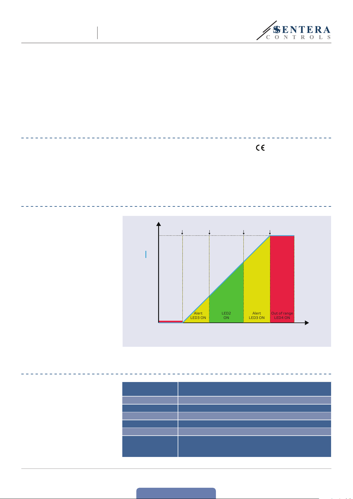
Output [%]
90
80
70
60
50
40
30
20
Out of range
10
LED4 ON
Min. pr essur e
limit
Measured value (pressure, volume flow
Cont rol
range min.
or air velocity) vs. Output
Cont rol
range max.
Max. pressur e
G-version: 18—34 VDC / 15—24 VAC ± 10 %
F-version: 18—34 VDC
Cable cross section 1,5 mm
2
Cable gland clamping range 3,5 mm
Connecting tube diameter 6—7 mm
limit
Differential pressure
Air vo lume flow
Air velocity
MIW-HPS-X-2-EN-000 - 14 / 03 / 2017 5 - 15
www.sentera.eu
back to the table of contents

2x Ø 3,4
HPS-X -2
DIFFERENTIAL PRESSURE
TRANSMITTER
ATTENTION
G and F-types devices cannot be used together in the same network. G and
F-type devices must be supplied by separate power supplies. Do not connect the
GND terminals of G and F-type devices together.
MOUNTING INSTRUCTIONS IN STEPS
Before you start mounting the HPS-X-2 differential pressure transmitter, read
carefully “Safety and Precautions”. Choose a smooth surface for an installation
location (awall, panel, etc.) and follow these steps:
1. Unscrew the front cover of the enclosure to remove it.
2. Fix the enclosure onto the surface by means of suitable fasteners while adhering
to the mounting dimensions shown in Fig. 1 Mounting dimensions and the correct
mounting position shown in Fig. 2 Mounting position.
Fig. 1 Mounting dimensions Fig. 2 Mounting position
49
Acceptable Not acceptable
HPS
_
+
HPS
52
_
+
+
_
HPS
3. Insert the cable though the grommet.
4. Connect as shown in Fig.3 Connections adhering to the information in section
“Wiring and connections”.
Fig. 3 Connections
Power supply
G: 15—24 VAC ± 10%/
18—34 VDC
F: 18—34 VDC
Modbus RTU
A /B
Analogue / digital (PWM) output
0—10 VDC/0—20 mA
5. Connec t the nozzles with the tubing.
6. Put back the front cover and fix it.
7. Switch on the power supply.
MIW-HPS-X-2-EN-000 - 14 / 03 / 2017 6 - 15
www.sentera.eu
back to the table of contents

HPS-X -2
DIFFERENTIAL PRESSURE
TRANSMITTER
NOTE
For sensor calibration and Modbus register reset procedures, refer to section
“Operating instructions”.
PWM voltage selection:
■
When the internal pull-up resistor (JP1) is connected , the voltage source is set via
Modbus holding register 39, i.e. 3,3 VDC or 12 VDC. See Fig. 4 Pull -up resistor jumper 1
Fig. 4 Pull-up resistor jumper 1
■
When JP1 is disconnected, the output type is Open collector. See Fig. 5 PWM
(Open collector) connection.
■
Only when JP1 is not connected and the analogue output (AO1) is assigned as
PWM output (via holding resister 31 - see Modbus Maps below), an external pullup resistor is used.
Fig. 5 PWM (Open collector) connection
External voltage
sour ce (5—50 VDC)
External voltage
sour ce (5—50 VDC)
VERIFICATION OF THE INSTALLATION INSTRUCTIONS
Continuous green LED1 indication as shown in Fig. 6 Power / Modbus communication
indication means the unit is supplied. If LED1 is not on, check the connections again.
Blinking green LED1 indication as shown in Fig. 6 Power / Modbus communication
indication means the unit has detected a Modbus network. If LED1 does not blink,
check the connections again.
NOTE
For more information, click here to refer to the product datasheet - Settings.
Fig. 6 Power / Modbus communication indication
Analogue / digital (PWM) output
0—10 VDC/0—20 mA
MIW-HPS-X-2-EN-000 - 14 / 03 / 2017 7 - 15
back to the table of contents
www.sentera.eu

HPS-X -2
DIFFERENTIAL PRESSURE
TRANSMITTER
ATTENTION
e status of the LEDs can be checked only when the unit is energised. Take the
relevant safety measures!
e Network Bus Terminator (NBT ) is controlled via Modbus RTU. By default the
NBT is disconnected. For more information, see the Modbus Registers Maps below.
If your unit starts or terminates the network, activate the NBT via Modbus RTU, see
the examples below.
Example 1 Example 2
Slave 1
Master
NBT
Slave 2
NOTE
NBT
Master
RX
ТX
NBT
Slave n
Connect the terminator only in the two most distant units on the network line!
NBT
Slave 1
Slave 2
RX
ТX
NBT
Slave n
OPERATING INSTRUCTIONS
Calibration procedure:
1. Disconnect the nozzles.
2. ere are two options for starting the calibration process:
Either write “1” in holding register 40 or press button SW1 for 4 seconds until
the green LED2 and yellow LED3 on the printed circuit board blink twice and
release it (see Fig.7Sensor calibration and Modbus register reset tact switch and
indication).
3. After 2 seconds the green LED2 and yellow LED3 will blink twice once again to
indicate that the calibration procedure has finished.
NOTE
Press and hold the button until both LEDs on the PCB blink twice and hold it until
both LEDs blink again three times. If the button is released before both LEDs blink
again three times, the sensor will have carried out a calibration procedure instead
of Modbus registers reset procedure.
Fig. 7 Sensor calibration and Modbus register reset
tact switch (SW1) and calibration indication
MIW-HPS-X-2-EN-000 - 14 / 03 / 2017 8 - 15
www.sentera.eu
back to the table of contents

HPS
HPS-X -2
DIFFERENTIAL PRESSURE
TRANSMITTER
Communication holding registers reset procedure:
1. Put the jumper onto pins 1 and 2 of the P4 connector for more than 20 s while the
device is powered. (See Fig. 8 Modbus holding register reset jumper ).
Fig. 8 Modbus holding register reset jumper
1
2
3
4
5
2. Modbus communication holding registers from 1 to 3 will be reset to the default
values.
3. Remove the jumper.
ATTENTION
Make sure that the nozzles are free and not connected.
LED indications (See Fig. 9):
1. When the green LED1 is on, the power supply is adequate and Modbus RTU
communication is active.
2. When the green LED2 is on, the measured value (pressure, volume or air velocity)
is between the minimum and maximum alert range.
3. When the yellow LED3 is on, the measured value (pressure, volume or air velocity)
is below the minimum alert range or above the maximum alert range.
4. When the red LED4 is on, the measured value (pressure, volume or air velocity) is
below the minimum measurement range or above the maximum.
Fig. 9 LED indications
5. Sensor element failure indication:
In case of failure of sensor element or loss of communication with it, the red
LED4 blinks. See Fig. 10.
Fig. 10 Sensor element error
HPS
MIW-HPS-X-2-EN-000 - 14 / 03 / 2017 9 - 15
back to the table of contents
www.sentera.eu

DIFFERENTIAL PRESSURE
HPS-X -2
TRANSMITTER
MODBUS REGISTER MAPS
INPUT REGISTERS
Data type Description Data Values
1
Output unsigned int. Output value in percentage 0—1.000 100 = 10,0%
HPS-X-1K0 -2
2
Differential pressure unsigned int. Measured differential pressure
3
Volume flow rate high unsigned int.
4
Volume flow rate low unsigned int.
5
Air velocity unsigned int. Measured air velocity 0—300 100 = 10 m/s
6
Air pressure/volume/
7
velocity alert flag
Air pressure/volume/
8
velocity range limit flag
9
Sensor fault unsigned int. Indicates sensor failure 0—1
10
unsigned int. Reserved, returns 0
unsigned int.
unsigned int.
unsigned int. Reserved, returns 0
Air Volume flow rate
e flag indicates that measured data is
outside the set alert values.
e flag indicates that measured data is
outside the set range limit values.
HPS-X-2K0 -2
HPS-X-4K0 -2
HPS-X-10K -2
HPS-X-1K0 -2
HPS-X-2K0 -2
HPS-X-4K0 -2
HPS-X-10K -2
0— 10.000
0— 20.000
0— 40.000
0—10.000
0—25.000
0—40.000
0—100.000
0—180.000
0—1
0—1
1.000 =
1.000 =
1.000 =
1.000 =
1.000 = 1.000 m
0 = Pressure/Volume/Velocity measurement is OK
Pressure/Volume/Velocity measurement is too
1 =
0 = Pressure/Volume/Velocity range is OK
1 = Pressure/Volume/Velocity range is too low/high
0 = Sensor OK
1 = Sensor fault (Red LED4 blinks)
100,0 Pa
100,0 Pa
100,0 Pa
1.000 Pa
3
low/high
/h
MIW-HPS-X-2-EN-000 - 14 / 03 / 2017 10 - 15
www.sentera.eu
back to the table of contents

DIFFERENTIAL PRESSURE
HPS-X -2
HOLDING REGISTERS
1 Device slave address unsigned int. Modbus device address 1—247 1
2 Modbus baud rate unsigned int. Modbus communication baud rate 0—6 2
3 Modbus parity mode unsigned int. Parity check mode
4 Device type unsigned int. Device type (Read-only)
5 HW version unsigned int.
6 FW version unsigned int.
7-10 Reserved, return 0
11 Minimum pressure range unsigned int. Minimum of the pressure range 0 - Max. pressure range minus 50 Pa 0
12 Maximum pressure range unsigned int. Maximum of the pressure range
13 Minimum pressure alert unsigned int.
14 Maximum pressure alert unsigned int.
15 Minimum volume flow range high unsigned int.
16 Minimum volume flow range low unsigned int.
17 Maximum volume flow range high unsigned int.
18 Maximum volume flow range low unsigned int.
19 Minimum volume flow alert high unsigned int.
20 Minimum volume flow alert low unsigned int.
21 Maximum volume flow alert high unsigned int.
22 Maximum volume flow alert low unsigned int.
23 Minimum air velocity range unsigned int. Minimum air velocity range value 0—(Maximum air velocity range minus 1 m/s) 0 100 = 10,0 m/s
24 Maximum air velocity range unsigned int. Maximum air velocity range value (Minimum air velocity range plus 1 m/s)—300 300 300 = 30,0 m/s
25 Minimum air velocity alert unsigned int. Minimum air velocity alarm value Min. air velocity range—Max. air velocity alarm 0 100 = 10,0 m/s
26 Maximum air velocity alert unsigned int.
27 Reserved, returns 0
28 Response time unsigned int. Response time selection 1—100 10 10 = 1,0 s
29 Power-up timer unsigned int.
30 K-factor. unsigned int.
31 Reserved, returns 0
Modbus network resistance
32
terminator (NBT)
33 Altitude unsigned int. Current altitude 0—5.000 0 1.000 = 1.000 m
34 Pitot air velocity unsigned int. Enables Air Velocity Readout. 0—1 0
2
35 Duct cross sectional area [ cm
36 Reserved, returns 0
37 Measurement readout unsigned int.
38 Operating mode unsigned int. Operating mode selection 1—3 1
39 Reserved, returns 0
40 Recalibrate sensor unsigned int. Sensor recalibration 0—1 0
For more information about Modbus over serial line, please visit: http://www.modbus.org/docs/Modbus_over_serial_line_V1_02.pdf
] unsigned int.
TRANSMITTER
Data type Description Data Default Values
unsigned int.
0 =
1 =
2 =
HPS-X-1K0 -2 =
HPS-X-2K0 -2 =
HPS-X-4K0 -2 =
HPS-X-10K -2 =
Hardware version of the device
(Read-only)
Firmware version of the device
(Read-only)
50 Pa
limit
flow range
HPS-X-1K0 -2
HPS-X-2K0 -2
HPS-X-4K0 -2
HPS-X-10K -2
HPS-X-1K0 -2
HPS-X-2K0 -2
HPS-X-4K0 -2
HPS-X-10K -2
Min. control
range plus
Minimum differential pressure
alarm value
Maximum differential pressure
alarm value
Minimum volume flow range value Maximum volume flow range minus 10 m³/h 0 10 = 10 m³/h
Maximum volume flow range value
Minimum volume flow alarm value
Maximum volume flow alarm value
Maximum mum air velocity alarm
value
Power-up timer before setting
alert and range limit flags.
K-factor according to motor / fan
specifications
Sets device as an end device on
the line
Calculation of the Volume Flow
Rate when K-factor is not known
4-digit measurement indication
ON / OFF
Min pressure range—max. pressure alarm 0
Max. pressure
Minimum volume flow
range plus 10 m³/h
Min. volume flow range—max. volume flow
Min. volume flow
range—max. volume
Min. velocity alarm—Max. air velocity range 300 300 = 30,0 m/s
50—10.000 Pa
50—20.000 Pa
50—40.000 Pa
50—10.000 Pa
8N1
8E1
8O1
1079
1080
1081
1082
XXX 0 x 0100 = HW version 1.00
XXX 0 x 0100 = FW version 1.00
10.000
20.000
40.000
10.000
HPS-X-1K0 -2
HPS-X-2K0 -2
HPS-X-4K0 -2
HPS-X-10K -2
alarm
HPS-X-1K0 -2
HPS-X-2K0 -2
HPS-X-4K0 -2
HPS-X-10K -2
0—1.000 60 s 100 = 100 s
0—1.000 0
0—1 0
0—32.000 0
0—1 1
1
10.000
20.000
40.000
10.000
10.000
20.000
40.000
10.000
25.000
40.000
100.000
180.000
25.000
40.000
100.000
180.000
1.000 =
1.000 =
1.000 =
1.000 =
1.000 =
1.000 =
1.000 =
1.000 =
20.000 = 20.000 m³/h
0 1.000 = 1.000 m³/h
10.000 = 10.000 m³/h
0 =
1 =
2 =
3 =
4 =
5 =
6 =
0 =
1 =
2 =
100 = 10,0 Pa
100 = 100,0 Pa (HPS-X-10K -2)
100 = 10,0 Pa
100 = 100,0 Pa (HPS-X-10K -2)
0 =
1 =
0 =
1 =
0 =
100
0 =
1 =
1 =
2 =
3 =
0 =
1 =
NBT disconnected
Differential pressure
Volume flow rate
4.800
9.600
19.200
38.400
57.600
115.200
230.400
100,0 Pa
100,0 Pa
100,0 Pa
1.000 Pa
100,0 Pa
100,0 Pa
100,0 Pa
1.000 Pa
NBT connected
Disabled
Enabled
Not used
100 cm
LED display off
LED display on
Air velocity
Inactive
Active
None
Even
Odd
2
(1)
(2)
(3)
(1)
To measure differential pressure, use use PSET-QF or PSET-PVC set;
(2)
To measure air flow volume while using PSET-PTx, enter the duct cross sectional area [cm²] in Modbus register 35. To measure air flow volume while using PSET-QF or
PSET-PVC, enter the K-factor of the fan in Modbus register 30;
(3)
To measure air velocity, use PSET-PTx set.
MIW-HPS-X-2-EN-000 - 14 / 03 / 2017 11 - 15
www.sentera.eu
back to the table of contents

HPS-X -2
DIFFERENTIAL PRESSURE
TRANSMITTER
INPUT REGISTERS (see Table Input registers above)
e input registers are read-only. All data can be read using the ‘Read Input Registers’
command. Table Input registers shows the returned data type and the way it should
be interpreted.
■
Input register 1 contains the value of the output as a percentage of the selected
control range.
■
Input register 2 contains the value of the currently measured differential pressure.
■
Input registers 3 and 4 provide information about the current air volume/flow
rate. Input register 3 holds the high significant word, while input register 4 holds
the low significant word. e value in these registers is equal to the K-factor of
the fan (holding register 30) multiplied by square root of the current differential
pressure. If K-factor is not known, volume flow rate is calculated via multiplying
the duct cross sectional area (holding register 35) by air flow velocity ( i.e. Pitot air
velocity enabled by holding register 34).
■
Input register 5 is “Air velocity”. It is active only when holding register 34 is set to “1”.
■
Input register 6 is not used. When addressed, it returns ‘0’.
■
Input register 7 indicates that measured air pressure, volume or velocity is
outside the set alert values. It is set to ‘1’ when the measured value is outside
the pressure, volume or velocity alert values defined by holding registers 13, 14,
19, 20, 21, 22, 25 and 26. It is not active during the power-up period defined by
holding register 29.
■
Input register 8 indicates that measured air pressure, volume or velocity is outside
the set range limit values. It is set to ‘1’ when the measured pressure is outside
the pressure, volume or velocity limit range values defined by holding registers 11,
12, 15, 16, 17, 18, 23 and 24. It is not active during the power-up period defined
by holding register 29.
■
Input register 9 indicates a problem with the sensor.
■
Input register 10 is not used. When addressed, it returns ‘0’.
NOTE
HOLDING REGISTERS (see Table Holding registers above)
ese registers are read/write registers and they can be managed via “Read Holding
Registers”, “Write Single Register” and “Write Multiple Registers” commands. e
registers that are not used are read-only and, therefore, writing in these registers
neither returns a Modbus error exception, nor makes any changes.
■
Holding register 1 contains the sensor address at which the sensor replies in a
Modbus network. e default address is ‘1’. It can be changed in two ways:
1. Send command “Write Single Register” with address ‘1’ and write the new
address value.
2. Connect only your unit to a master controller or a PC application, send the
command “Write Single Register” to address ‘0’ (Modbus broadcast address)
and write a new address value.
■
e next two holding registers (2 and 3) also contain Modbus settings. Changing
these registers changes the communication settings. e default Modbus settings
are as stated in the Modbus Protocol Specification.
■
e next three holding registers (4, 5 and 6) are read-only. ey return information
about the sensor hardware and firmware versions.
■
e next four holding registers (7, 8, 9 and 10) are not used. ey are read-only.
Writing in these registers neither returns a Modbus error exception, nor makes
any changes!
■
Holding registers 11 determines the minimum pressure range. It cannot be set
higher than the maximum pressure range minus the minimum pressure range span
(i.e. 50 Pa).
MIW-HPS-X-2-EN-000 - 14 / 03 / 2017 12 - 15
back to the table of contents
www.sentera.eu

HPS-X -2
DIFFERENTIAL PRESSURE
TRANSMITTER
NOTE
NOTE
e minimum pressure range cannot be higher than the maximum control range
minus 50 Pa.
■
Holding register 12 defines the maximum pressure range. It cannot be set lower
than the minimum pressure range plus the minimum pressure range span (i.e.
50 Pa). is register accepts values as specified in the Modbus map. (See Table
Holding registers above). Writing values other the those specified in the Modbus
map does not change anything in this register.
e maximum pressure range cannot be less than the minimum range plus 50 Pa.
■
Holding registers 13 and 14 contain the minimum and maximum differential
pressure alarm value respectively.
■
Holding registers 15 and 16 hold the minimum volume flow range, which cannot
be set higher than the maximum volume flow range minus the minimum volume
flow range span (10 m³/h). e air volume flow rate is measured in m3/h. Holding
register 15 contains the high significant word, while holding register 16 contains
the low significant word of the minimum volume flow rate range.
■
Holding registers 17 and 18 hold the maximum volume flow, which cannot be set
lower than the minimum volume flow range plus the minimum volume flow range
span (10 m³/h). e air volume flow rate is measured in m3/h. Holding register
17 contains the high significant word, while holding register 18 contains the low
significant word of the maximum volume flow rate range.
■
Holding registers 19 and 20 hold the minimum volume flow alarm value. e
air volume flow rate is measured in m3/h. Holding register 19 contains the high
significant word, while holding register 20 contains the low significant word of the
minimum volume flow rate alert.
■
Holding registers 21 and 22 hold the maximum volume flow alarm value. e
air volume flow rate is measured in m3/h. Holding register 21 contains the high
significant word, while holding register 22 contains the low significant word of the
maximum volume flow rate alert.
■
Holding registers 23 and 24 hold the minimum and maximum air velocity range
respectively. e minimum air velocity range cannot be set higher than the
maximum air velocity range minus minimum air velocity range span (1 m/s). e
maximum air velocity range, cannot be set lower than the minimum air velocity
range plus the minimum air velocity range span (1 m/s).
NOTE
NOTE
MIW-HPS-X-2-EN-000 - 14 / 03 / 2017 13 - 15
e minimum value cannot be higher than the maximum value. When a value
higher than the defined maximum is written inside a register, it automatically
becomes equal to the predefined maximum value.
■
Holding register 25 and 26 hold the minimum and maximum air velocity alarm
values respectively.
If a value written in a holding register is lower than the predefined minimum value,
the unit automatically adjusts the minimum limit to the new maximum limit value.
(For example: when min. = 200 and max. = 1.000, if the max. value is changed to
150, i.e. is lower than the min. value, the unit automatically sets the min. value to 150
because the min. cannot be higher than the max.)
■
Holding register 27 is not used. When addressed, it returns “0”.
■
Holding register 28 contains the response time, which can be given values from 1
to 100, where 10 = 1,0 second.
www.sentera.eu
back to the table of contents

HPS-X -2
DIFFERENTIAL PRESSURE
TRANSMITTER
■
Holding register 29 contains the value of the ‘Power-up timer’ before setting the
alert and range limit flags. e default value is 60 s. During this interval the alerts
and range limits are not compared with the current differential pressure / volume /
velocity and alert and range limit flags registers remain ‘0’. You can change the value
in this register only within the first 60 s after you have switched on your unit.
■
Holding register 30 holds the K-factor. Enter the K-factor of the used fan/drive,
if it is known (check the datasheets of the selected fan / drive). e default value
is ‘0’, and you are allowed to write values in the range of 0—1.000. Writing values
out of this range does not change anything in this register.
■
Holding register 31 is not used. When addressed, it returns “0”.
■
Holding register 32 specifies if the device is an end device on the line or not via
connecting the NBT.
■
Holding register 33 holds information about the current altitude varying from “0”
to “5.000”. e default value is ‘0‘, i.e. 0 m.
■
Holding register 34 enables air velocity readout. If the value is ‘0’, air velocity
readout is disabled and if the value is ‘1’, air velocity readout is enabled and it is
accessible in input register 5. PSET-PTX-200 Pitot tube is necessary.
■
Holding register 35 is used for calculation of the volume flow rate when K-factor
is not known. is register accepts values from 0 to 32.000. When the value is 0,
it is not used, if in use it takes values from 1 to 32.000 corresponding to the duct
cross sectional area in cm2.
■
Holding register 36 is not used. When addressed, it returns “0”.
■
Holding register 37 is used to define if the LED display will be on or off.
■
Holding registers 38 defines the operating modes, i.e. differential pressure,
volume flow rate or air velocity.
■
Holding register 39 is not used. When addressed, it returns “0”.
■
Holding register 40 is used for sensor recalibration.
MIW-HPS-X-2-EN-000 - 14 / 03 / 2017 14 - 15
back to the table of contents
www.sentera.eu

DIFFERENTIAL PRESSURE
HPS-X -2
TRANSMITTER
TRANSPORT AND STOCK KEEPING INFORMATION
Avoid shocks and extreme conditions; stock in original packing.
WARRANTY INFORMATION AND RESTRICTIONS
Two years from the delivery date against defects in manufactur ing. Any modifications
or alterations to the product after the date of publication relieve the manufacturer
of any responsibilities. e manufacturer bears no responsibility for any misprints or
mistakes in this data.
MAINTENANCE
In normal conditions this product is maintenance-free. If soiled, clean with a dr y or
dampish cloth. In case of heavy pollution, clean with a non-aggressive product. In
these circumstances the unit should be disconnected from the supply. Pay attention
that no fluids enter the unit. Only reconnect it to the supply when it is completelydry.
MIW-HPS-X-2-EN-000 - 14 / 03 / 2017 15 - 15
back to the table of contents
www.sentera.eu
Loading...