

Page 1
Mounting and operating instructions
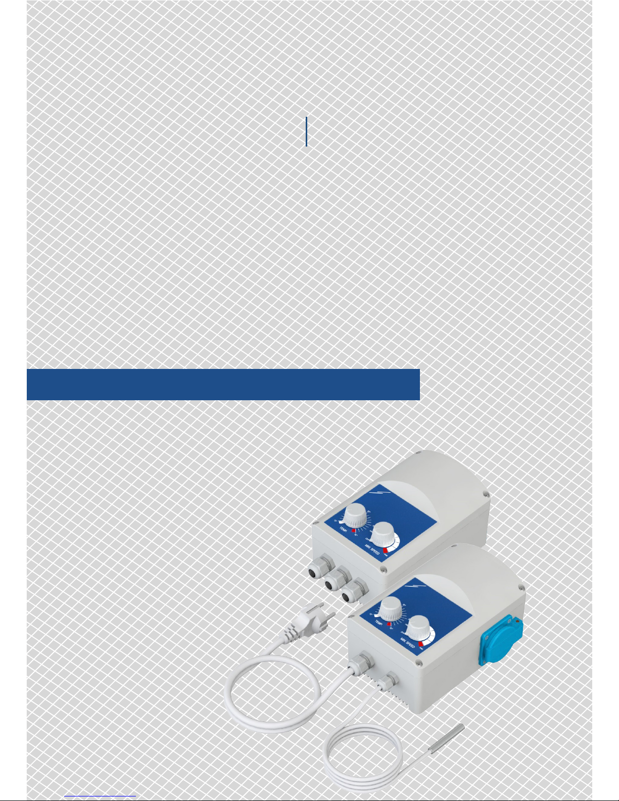
GTEX1-60
ELECTRONIC FAN SPEED
CONTROLLER
Page 2
www.sentera.eu
MIW-GTE-EN-000 - 17 / 01 / 2018 2 - 11
Table of contents
SAFETY AND PRECAUTIONS 3
PRODUCT DESCRIPTION 4
ARTICLE CODES 4
INTENDED AREA OF USE 4
TECHNICAL DATA 4
STANDARDS 5
WIRING AND CONNECTIONS 5
OPERATIONAL DIAGRAM 5
MOUNTING INSTRUCTIONS IN STEPS 6
VERIFICATION OF INSTALLATION INSTRUCTIONS 9
MODBUS REGISTERS MAPS 10
TRANSPORT AND STOCK KEEPING INFORMATION 11
WARRANTY INFORMATION AND RESTRICTIONS 11
MAINTENANCE 11
ELECTRONIC
FAN SPEED CONTROLLER
GTEX1-60
Page 3
www.sentera.eu
MIW-GTE-EN-000 - 17 / 01 / 2018 3 - 11
back to the table of contents
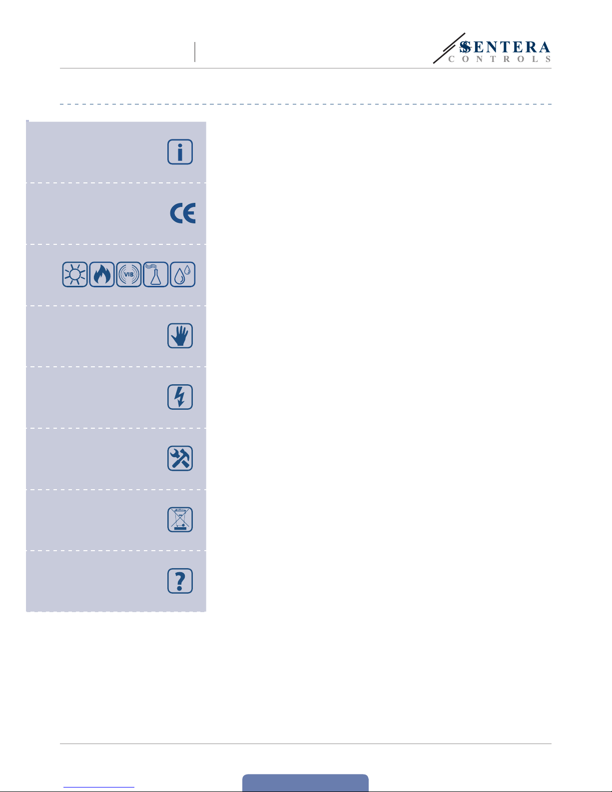
SAFETY AND PRECAUTIONS
Read all the information, the datasheet, mounting and operating instructions and
study the wiring and connection diagram before working with the product. For
personal and equipment safety, and for optimum product performance, make sure you
entirely understand the contents before installing, using, or maintaining this product.
For safety and licensing (CE) reasons, unauthorise d conversion and/ or modificat ions
of the product are inadmissible.
e product should not be exposed to abnormal conditions, such as: extreme
temperatures, direct sunlight or vibrations. Long-term exposure to chemical
vapours in high concentration can affect the product performance. Make sure the
work environment is as dry as possible; avoid condensation.
All installations shall comply with local health and safety regulations and local
electrical standards and approved codes. is product can only be installed by an
engineer or a technician who has expert knowledge of the product and safety
precautions.
Avoid contacts with energised electrical parts; always treat the product as if it is
live. Always disconnect the power supply before connecting, servicing or repairing
the product.
Always verify that you apply appropriate power supply to the product and use
appropriate wire size and charac teristics. Make sure that all the screws and nuts
are well tightened and fuses (if any) are fitted well.
Recycling of equipment and packaging should be taken into consideration and these
should be disposed of in accordance with local and national legislation/regulations.
In case there are any questions that are not answered, please contact your
technical support or consult a professional.
ELECTRONIC
FAN SPEED CONTROLLER
GTEX1-60
Page 4
www.sentera.eu
MIW-GTE-EN-000 - 17 / 01 / 2018 4 - 11
back to the table of contents
PRODUCT DESCRIPTION
e GTE fan speed controller automatically regulates the speed of single phase
voltage controllable motors (230 VAC / 50—60 Hz) according to the measured
temperature values. e maximum speed can be adjusted via an internal
trimmer. e minimum speed and temperature setpoint can be adjusted via
external potentiometers. ere are two product versions: -DM with Modbus RTU
communication and -DT with an integrated motor socket, power cable and a PT500
temperature probe. e fan speed will increase as the measured temperature
exceeds the setpoint temperature.
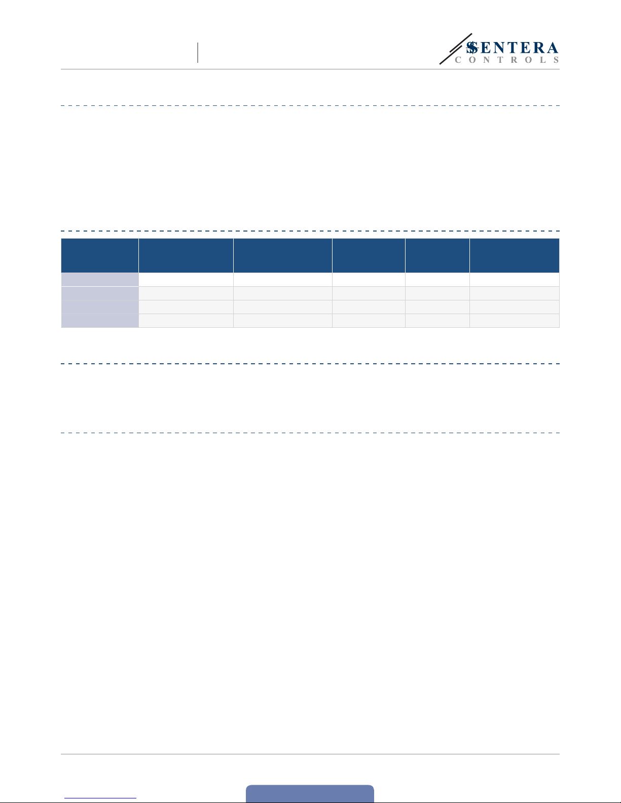
ARTICLE CODES
Code Temperature range
PT500 temperature
sensor included
Schuko socket
for simple motor
connection
Integrated
power supply
cable
Modbus RTU
GTE21-60-DM 5—35 ºC no no no yes
GTE21-60-DT 5—35 ºC yes yes yes no
GT E-1-6 0-DM 15—35 ºC no no no yes
GT E-1-6 0-DT 15—35 ºC yes yes yes no
INTENDED AREA OF USE
■
Greenhouses and temperature controlled ventilation systems
■
For indoor use only
TECHNICAL DATA
■
Supply voltage: 230 VAC ± 10 %/ 50—60 Hz
■
Output load: max. 6 A
■
Potentiometer for minimum speed setting
■
Internal trimmer for maximum speed setting
■
Adjustable hysteresis and proportional range
■
Potentiometer for temperature setpoint range: 5—35 °C or 15—35 °C,
depending on the product version
■
PT500 temperature probe input (pre-wired for the -DT version and separately
available for the -DM version)
■
Modbus RTU communication (only in -DM version)
■
Schuko socket for motor connection (only in -DT version)
■
Euro plug for power supply (only in -DT version)
■
Pre-wired temperature sensor and supply cable (only in -DT version)
■
Enclosure: plastic R-ABS, V; grey colour (RAL 7035)
■
Protection standard: IP54 (according to EN 60529)
■
Storage temperature: -40—50 °C
■
Operating ambient conditions:
►
temperature: 0—40 °C
►
rel. humidity: <95 % rH (non-condensing)
■
Storage temperature: -40—50 °C
ELECTRONIC
FAN SPEED CONTROLLER
GTEX1-60
Page 5

www.sentera.eu
MIW-GTE-EN-000 - 17 / 01 / 2018 5 - 11
back to the table of contents
STANDARDS
■
Low Voltage Directive 2014/35/EC
■
EMC Directive 2014/30/EC: EN 61000-3-2:2014, EN 61000-6-2:2005/
AC:2005 and EN 61000-6-3:2007/A1:2011/AC:2012
■
WEE E Di r ective 2012/19/EC
■
RoHs Directive 2011/65/EC
WIRING AND CONNECTIONS
GTEX1-60-DM
L
Supply voltage 230 VAC / 50—60 Hz – mono phase ± 10%
N
Neutral
L1
230 VAC not regulated output (max. 2 A)
GND, T (TEMP.)
PT500 temperature sensor
A
RS485 signal A
/B
RS485 signal /B
P5
Motor connection
GTEX1-60-DT
L
Supply voltage 230 VAC / 50—60 Hz – mono phase ± 10%
N
Neutral
PE
Ground
L1
230 VAC not regulated output (max. 2 A)
GND, T (TEMP.)
PT500 temperature sensor
Schuko socket Motor connection
OPERATIONAL DIAGRAM
Control curve
10
0
90
80
70
60
50
40
30
20
10
Min 5 / 15 °C Max 35 °C
Ts
[%]
Output
speed
Temperature [°C]
Minimum speed
Hyst eresis (0.5, 1, 2 or 3° C)
Proportional range
(2, 4, 6 or 8 °C)
Maximum
speed
ELECTRONIC
FAN SPEED CONTROLLER
GTEX1-60
Page 6

www.sentera.eu
MIW-GTE-EN-000 - 17 / 01 / 2018 6 - 11
back to the table of contents
MOUNTING INSTRUCTIONS IN STEPS
Before you start mounting the GTE controller, read carefully “Safety and
Precautions”. Choose a flat surface for installation (e.g. a wall, panel, etc.) and
follow these steps:
1. Insert the supply and sensor cables through the cable glands and do the wiring
according to the information in section “Wiring and connections” while adhering
to Fig. 1 below.
Fig. 1 Wiring diagram
Power supply
230 VAC no t regulated
output (max. 2 A )
PT50 0
connection
Modbus RTU Ground
Motor connection
(Max 6 A)
Only for -DM version
NOTE
For the -DT version the power supply and the temperature sensor (PT500) are
included in the set and factory connected. Also, the -DT version has a Schuko
socket to plug in the motor / fan. If your unit is -DT, please skip step 1.
2. Fix the jumpers accordingly - see Fig. 2 Jumper positions below.
NOTE
e -DM version can be used both as a stand-alone unit or in conjunction with
a computer and operated by Sentera’s 3SModbus software or the Sensistant
configurator. When used stand-alone, its jumpers need to be set to the desired
values. When used in Modbus mode, its parameters are set via Modbus RTU,
so the jumpers can remain in their factory set positions. Refer to the Modbus
Holding Registers Ta ble below for the relevant settings.
Fig. 2 Jumper positions
Propor. Range (JP1 & JP2) Hysteresis (JP3 & JP4) Off-level (JP5 & JP6)
1
2
2°C
3
4
0,5°C
5
On
1
2
4°C (factory preset)
3
4
1°C
5
Off (factory pre set)
1
2
6°C
3
4
2°C (factory preset)
1
2
8°C
3
4
3°C
ELECTRONIC
FAN SPEED CONTROLLER
GTEX1-60
Page 7

www.sentera.eu
MIW-GTE-EN-000 - 17 / 01 / 2018 7 - 11
back to the table of contents
-DM version mounting steps: Go t o -DT version ▶
1. Make sure the GTE controller is not connected to the mains supply.
2. Unscrew the front cover and open the enclosure. Mind the wires that connect
the potentiometer with the printed circuit board.
3. Fix the unit to the wall or panel using the provided screws and dowels. Mind the
correct mounting position and unit mounting dimensions. (See Fig. 3 Mounting
dimensions and Fig. 4 Mounting position.).
Fig. 3 Mounting dimensions Fig. 4 Mounting position
140
102
124
97
124
204
Acceptable Not acceptable
4. Set the maximum speed trimmer to the desired value. You can choose from the
range 170—230 VAC. e factory setting is 230 VAC.
5. Optional setting:
■
e Network Bus Terminator (NBT ) (see Fig. 5 NBT j um pe r) used with Modbus
RTU. By default the NBT is disconnected.
Fig. 5 NBT jumper
NBT is connected
NBT is disconnected
(factory pre-set)
NOTE
Connect the NBT only in the two most distant units on the network line!
■
Connect the NBT by placing the jumper onto the pins as indicated above only
if your unit starts or terminates the network. Skip this step if your unit is not
the first or last on the network. See the examples below for more information.
Example 1 Example 2
Slave 1
RX
ТX
NBT
NBT
NBT
Slave 2
Master
Slave n
Slave 2
Slave 1
RX
ТX
NBT
NBT
Master
Slave n
6. Put back the front cover and fix it.
ELECTRONIC
FAN SPEED CONTROLLER
GTEX1-60
Page 8

www.sentera.eu
MIW-GTE-EN-000 - 17 / 01 / 2018 8 - 11
back to the table of contents
-DT version mounting steps: Back to -DM version ▶
1. Make sure the GTE controller is not connected to the mains supply.
2. Unscrew the front cover and open the enclosure. Mind the wires that connect
the potentiometer with the printed circuit board.
3. Fix the unit to the wall or panel using the provided screws and dowels. Mind the
correct mounting position and unit mounting dimensions. (See Fig. 6 Mounting
dimensions and Fig. 7 Mounting position.)
Fig. 6 Mounting dimensions Fig. 7 Mounting position
140
102
140
97
140
204
Acceptable Not acceptable
4. Set the maximum speed trimmer to the desired value (see Fig. 8 Max. speed
trimmer ). You can choose from the range 170—230 VAC. e factory setting is
230VAC.
Fig. 8 Max. speed trimmer
Vmax se t from 170 VAC (left) to 230 VAC
(righ t) (factor y pre-set to max.)
6. Put back the front cover and fix it.
7. Plug the motor / fan cable into the Schuko socket.
ELECTRONIC
FAN SPEED CONTROLLER
GTEX1-60
Page 9

www.sentera.eu
MIW-GTE-EN-000 - 17 / 01 / 2018 9 - 11
back to the table of contents
VERIFICATION OF INSTALLATION INSTRUCTIONS
ATTENTION
Mind that the cables are live. Take the relevant safety measures.
1. Plug in the supply cable.
2. Switch on the controller via the illuminated ON/OFF switch.
3. Position the TEMP. potentiometer to max. position (35 °C). (See Fig. 9 -DM
version and Fig. 10 -DT version)
Fig. 9 -DM version Fig. 10 -DT version
On /off
switch
Temperature
potentiometer
Min. speed
potentiometer
On /off
switch
Temperature
potentiometer
Min. speed
potentiometer
Schuko
socket
Integrated power
supply cable - Euro
standard
Integrated cable
with PT500
sensor
4. e connected motor will run at min. speed.
5. Adjust the TEMP. potentiometer to temperature equal to the ambient
temperature.
6. e motor / fan will run at min. speed and speed up if the ambient temperature
rises ( hold the temperature probe in your hands to check).
7. Adjust the temperature potentiometer to the min. position (5 °C for GTE21-60-
DM and GTE21-60-DT or 15 °C for GTE-1-60-DM and GTE-1-60-DT)
8. e motor will run at max. selected speed if the difference between the setpoint
temperature and the ambient temperature is more than the value of the selected
proportional range.
9. If the unit does not operate as explained above, check the connections and
settings.
ELECTRONIC
FAN SPEED CONTROLLER
GTEX1-60
Page 10

www.sentera.eu
MIW-GTE-EN-000 - 17 / 01 / 2018 10 - 11
back to the table of contents
MODBUS REGISTERS MAPS
INPUT REGISTERS (Read-onl y)
Data type Description Data Values
1 Temperature input unsigned int. Analog temperature input 0—600
0 =
600 =
0,0 °C
60.0 °C
2 Vmax unsigned int. Max. motor spe ed value 170—230
170 =
230 =
170 VAC
230 VAC
3 Vmin unsigned int. Min. mo tor speed value 80 —160
80 =
160 =
80 VAC
160 V AC
4 Output voltage unsigned int. Current output voltage 0,80—2 30
0 =
80 =
230 =
0 VAC
80 VAC
230 VAC
5 Temperature setpoint unsigned int. Temperature setpoint value
GTE21-60-DM
GTE-1-60-DM
50—350
150—350
50 =
150 =
350 =
5,0 °C
15, 0 ° C
35,0 °C
6 Proportional range unsigned int. Proportional temperature value 1—4
1 =
2 =
3 =
4 =
2 °C
4 °C
6 °C
8 °C
7 Hysterisis unsigned int. Hysterisi s value 1—4
1 =
2 =
3 =
4 =
0,5 °C
1 °C
2 °C
3 °C
8 Off lev el unsigned int. Off lev el value 0, 1
0 =
1 =
OFF
ON
9 Senso r stat us unsigned int. Input s ensor status 0, 1
0 =
1 =
sensor connected
sensor disconnected
10 Reser ved, Returns ‘0’
Note: e input r egist ers ca n be read v ia the Modbus command: “Re ad input regis ters”.
HOLDING REGISTERS (Read/wr ite)
Data type Description Data Default Values
1 Address unsigned int. Modbus device address 1—247 1
2 Modbus baud rate unsigned int. Modbus communication baud rate 1—4 2
1 =
2 =
3 =
4 =
9.600
19.200
38.400
57.600
3
Modbus parity
mode
unsigned int. Parity check mode 0—2 1
0 =
1 =
2 =
8N1
8E1
8O1
4 Device type unsigned int. Device type (Read only)
GTE21-60-DM=3013
GTE-1-60-DM=3003
5 HW version unsigned int.
Hard ware ve rsion o f the dev ice
(Read only)
XXXX
GTE21-60-DM
GTE-1-60-DM
0x0210 =
0x020 0 =
HW ver sion 2.10
HW ver sion 2.00
6 SW version unsigned int.
Sof tware ve rsion of t he device ( Read
only)
XXXX
GTE21-60-DM 0x030 0 = SW version 3.00
GTE-1-60-DM 0x 0230 = SW versi on 2.30
7 Operating mode unsigned int. Mod e of oper ation 0—1 0
0 =
1 =
Standalone mode
Modbus mode
8 Output overwrite unsigned int. O utput ove rwrite mode 0—1 0
0 =
1 =
Disabled
Enabled
9-10 Reser ved, ret urn ‘0’
11 Vmax unsigned int. M ax. mot or speed val ue 170 —23 0 230
170 =
230 =
170 VAC
230 VAC
12 Vmin unsigned int. M in. motor speed value 80 —160 80
80 =
160 =
80 VAC
160 V AC
13
Temperature
setpoint
unsigned int. Temperature setpoint value
GTE21-60-DM
GTE-1-60-DM
50—350
150—350
150
50 =
150 =
350 =
5,0 °C
15, 0 °C
35,0 °C
14
Proportional
range
unsigned int. Pr oportional range value 1—4 2
1 =
2 =
3 =
4 =
2 °C
4 °C
6 °C
8 °C
15 Hysterisis unsigned int. Hysterisis value 1— 4 3
1 =
2 =
3 =
4 =
0,5 °C
1 °C
2 °C
3 °C
16 Off lev el unsigned int. Off level val ue 0—1 0
0 =
1 =
OFF
ON
17
Modbu s time- out
control
unsigned int. Modbus time-out control value 0—1 0
0 =
1 =
Disabled
Enabled
18
Modbust timeout
unsigned int. Modbus time-out value 0—60 1
1 =
60 =
1 min
60 min.
19 Vout unsigned int. Set override output voltage 0, 80—23 0 0
0 =
80 =
230 =
0 VAC
80 VAC
230 VAC
20 Reserved, r etur ns ‘0’
Note: e holding registers can be managed via the following Modbus commands: “Read Holding Registers”, “Write Single Register” or “Write Multiple Registers”.
If you w ant to find o ut more about Mo dbus ove r serial line, ple ase visit: http://www.modbus.org/docs/Modbus_over_serial_line_V1_02.pdf
ELECTRONIC
FAN SPEED CONTROLLER
GTEX1-60
Page 11

www.sentera.eu
MIW-GTE-EN-000 - 17 / 01 / 2018 11 - 11
back to the table of contents
TRANSPORT AND STOCK KEEPING INFORMATION
Avoid shocks and extreme conditions; stock in the original packing.
WARRANTY INFORMATION AND RESTRICTIONS
Two years fr om the delive ry date against defects in manufactur ing. Any modi fications
or alterations to the product after the date of publication relieve the manufacturer
of any responsibilities. e manufacturer bears no responsibility for any misprints or
mistakes in this data.
ATTENTION
Use only fuses of the type and rating specified above; otherwise, loss of warranty
will ensue.
MAINTENANCE
In normal conditions this product is maintenance-free. If soiled, clean with a dr y or
dampish cloth. In case of heavy pollution, clean with a non-aggressive product. In
these circumstances the unit should be disconnected from the supply. Pay attention
that no fluids enter the unit. Only reconnect it to the supply when it is completelydry.
ELECTRONIC
FAN SPEED CONTROLLER
GTEX1-60
 Loading...