

Sentera Controls EVSS1, EVSS Series, EVSS1 Series, EVSS-1-15-DM, EVSS-1-60-DM Mounting And Operating Instructions
...
ELECTRONIC FAN
SPEED CONTROLLER
EVSS
Mounting and operating instructions
WITH TK

ELECTRONIC FAN SPEED
EVSS
CONTROLLER WITH TK
Table of contents
SAFETY AND PRECAUTIONS 3
PRODUCT DESCRIPTION 4
ARTICLE CODES 4
INTENDED AREA OF USE 4
TECHNICAL DATA 4
STANDARDS 5
WIRING AND CONNECTIONS 5
OPERATIONAL DIAGRAMS 6
MOUNTING INSTRUCTIONS IN STEPS 8
VERIFICATION OF INSTALLATION INSTRUCTIONS 10
OPERATING INSTRUCTIONS 11
MODBUS REGISTER MAPS 12
TRANSPORT AND STORAGE 16
WARRANTY AND RESTRICTIONS 16
MAINTENANCE 16
MIW-EVSS-DM-EN-000 - 18 / 12 / 2018 2 - 16
www.sentera.eu

ELECTRONIC FAN SPEED
EVSS
CONTROLLER WITH TK
SAFETY AND PRECAUTIONS
Read all the information, the datasheet, mounting and operating instructions and
study the wiring and connection diagram before working with the product. For
personal and equipment safety, and for optimum product performance, make sure you
entirely understand the contents before installing, using, or maintaining this product.
For saf ety and li censing (CE ) reasons , unauthor ised conver sion and/ or modifi cations
of the product are inadmissible.
e product should not be exposed to abnormal conditions, such as: extreme
temperatures, direct sunlight or vibrations. Long-term exposure to chemical
vapours in high concentration can affect the product performance. Make sure the
work environment is as dry as possible; avoid condensation.
All installations shall comply with local health and safety regulations and local
electrical standards and approved codes. is product can only be installed by an
engineer or a technician who has expert knowledge of the product and safety
precautions.
Avoid contacts with energised electrical parts. Always disconnect the power
supply before connecting, servicing or repairing the product.
Always verify that you apply appropriate power supply to the product and use
appropriate wire size and characteristics. Make sure that all the screws and nuts
are well tightened and fuses (if any) are fitted well.
Recycling of equipment and packaging should be taken into consideration and these
should be disposed of in accordance with local and national legislation/regulations.
In case there are any questions that are not answered, please contact our technical
support or consult a professional.
MIW-EVSS-DM-EN-000 - 18 / 12 / 2018 3 - 16
www.sentera.eu
back to the table of contents
ELECTRONIC FAN SPEED
EVSS
CONTROLLER WITH TK
PRODUCT DESCRIPTION
ARTICLE CODES
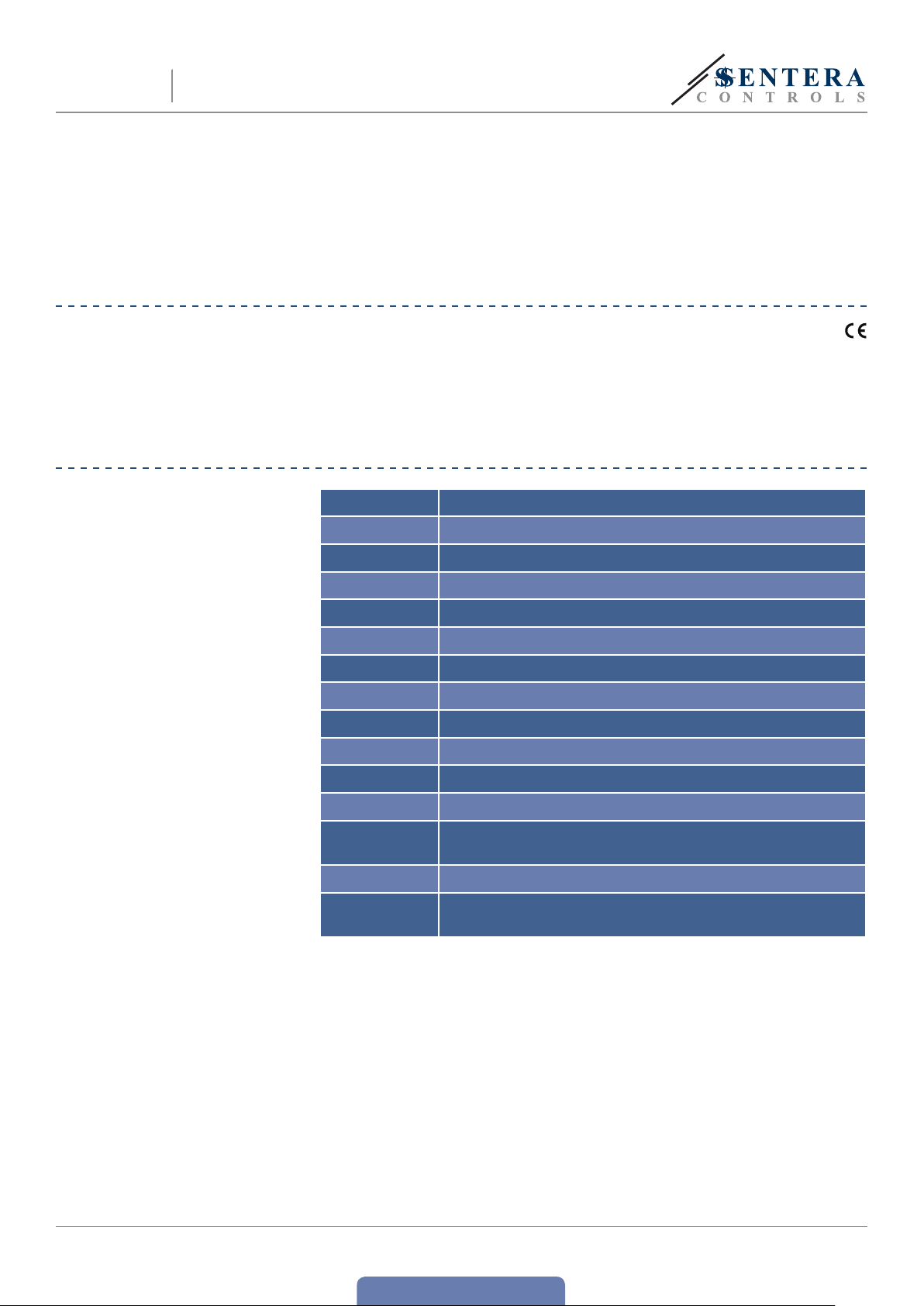
e EVSS1 is an electronic speed controller which controls the speed of singlephase (230 VAC /50—60 Hz) voltage controllable electric motors. It is equipped
with Modbus RTU (RS485) communication, an alarm relay output and thermal
contacts to provide overheating protection of motors with cut-out contacts. e
EVSS controller provides a wide range of functionalities: remote control options,
adjustable off level, min. and max. output voltage settings, and time-limited motor
operation initiated by a logic or switch signal.
Code Nominal current, [A] Fuse rating, [A]
EVSS -1-15 -DM 1,5 (5*20 mm) F 3,15 A H 250 VAC
EVSS -1-30 -DM 3,0 (5*20 mm) F 5,0 A H 250 VAC
EVSS -1- 60-DM 6,0 (5*20 mm) F 10,0 A H 250 VAC
E V SS -1100-DM 10,0 (6,3*32 mm) F 16,0 A H 250 VAC
INTENDED AREA OF USE
TECHNICAL DATA
■
Fan speed control in ventilation systems
■
For indoor use only
■
Power supply: 230 VAC ±10 %-50—60 Hz
■
Analog input:
►
voltage: 0—10 VDC/10—0 VDC
►
current: 0—20 mA/20—0 mA
■
Analog input modes: ascending or descending
■
Analog input functionality: Normal mode / Logic mode
■
Remote control input: normal or timer functionality
■
Regulated output: 30—100 % Us
■
Max. output load: depends on the version
■
Unregulated output, L1: 230 VAC (50/60 Hz)/max. 2 A
■
Alarm output (230 VAC / 1 A)
■
Min. output voltage setting, Umin: 30—70 % Us (69—161 VAC), selectable by
trimmer or via Modbus
■
Max. output voltage setting, Umax: 75—100 % Us (175—230 VAC), selectable by
trimmer or via Modbus
■
Off level, adjustable by trimmer or via Modbus:
►
0—4 VDC/0—8 mA for ascending mode
►
10—6 VDC/20—12 mA for descending mode
■
Kick start or soft start
■
Low voltage supply output: +12 VDC/1 mA for external potentiometer
■
Modbus communication
■
Operating indication:
►
continuous green: normal operation
►
blinking green: stand-by
■
Overvoltage and overcurrent protection
■
ermal inputs for motor overheating protection
MIW-EVSS-DM-EN-000 - 18 / 12 / 2018 4 - 16
back to the table of contents
www.sentera.eu
ELECTRONIC FAN SPEED
EVSS
CONTROLLER WITH TK
■
Motor overheating indication
■
Enclosure: plastic R-ABS, UL94-V0; grey colour (R AL 7035)
■
Protection standard: IP54 (according to EN 60529)
■
Operating ambient conditions:
►
►
■
Storage temperature: -40—50 °C
STANDARDS
■
Low Voltage Directive 2006/95/EC
■
EMC Directive 2004/108/EC: EN 61326
■
WEE E Di rective 2012/19/EU
■
RoHs Directive 2011/65/EU
WIRING AND CONNECTIONS
L Supply voltage 230 VAC ±10 % / 50—60 Hz
temperature: -20—40 °C
rel. humidity: < 95 % rH (non-condensing)
N Neutral
PE Earth terminal
L1 Unregulated output (230 VAC/max. 2 A)
U1, U2 Regulated output to the motor
TK, TK ermal contact
N Neutral
AL Alarm output (230 VAC / 1 A)
SW Remote control switch
A Modbus RTU (RS485) signal A
/B Modbus RTU (RS485) signal /B
+V Supply output +12 VDC/1 mA
Ai
GND Ground
Connections
Analog input (0—10 VDC/0—20 mA) or
(10—0 VDC/20—0 mA)
Cable cross section: max. 2,5 mm
Cable gland clamping range: 3—6 mm/ 5—10 mm
2
MIW-EVSS-DM-EN-000 - 18 / 12 / 2018 5 - 16
back to the table of contents
www.sentera.eu
[%]
[VDC]/[mA]
[%]
[VDC]/[mA]
Uout=Umin+
Aimax
Ai
(Umax-Umin)
Uout=Umax-
Aimax
Ai
(Umax-Umin)
/
U,
Uout=Umax+
Aimax-Off level
Ai-Off level
(Umax-Umin)
Uout=Umax-
Aimax-Off level
Ai-Off level
(Umax-Umin)
t [s]
Umax
Umin
0
Uout, [%]
100
75
70
30
10 VDC /
20 mA
Ai,
[VDC]/
[mA]
t [s]
Umax
Umin
Uout, [%]
100
75
70
30
10 VDC /
20 mA
0 VDC /
0 mA
Ai,
[VDC]/
[mA]
ELECTRONIC FAN SPEED
EVSS
CONTROLLER WITH TK
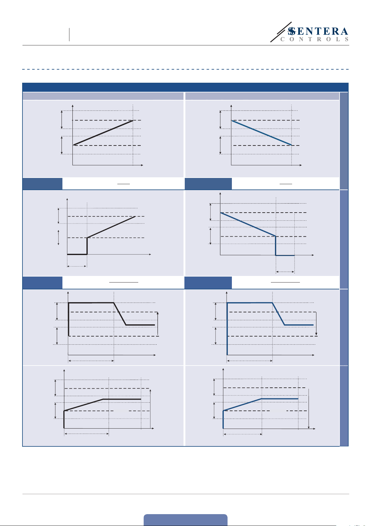
OPERATIONAL DIAGRAMS
Normal / Remote operating modes
Ascending input mode Descending input mode
U
out
100
Umax
range
Umin
range
Ascending mode
calculation formula
,
Umax
75
70
Umin
30
0
10 VDC
20 mA
Ai ,
Descending mode
calculation formula
U
Umax
range
Umin
range
out
100
,
Umax
75
70
Umin
30
0
10 VDC
20 mA
Ai ,
Off level disabled
100
Umax
range
75
70
Umin
range
30
Ascending mode
calculation formula
Uout, [%]
100
Umax
range
75
70
Umin
range
30
[%]out
Umax
Umin
Umax
Umin
0
0
Off level
range
Kick start time
Off level
4 VDC
8 mA
10 VDC
,Ai
20 mA
[VDC]
[mA]
Ai,10 VDC / 20 mA
0 VDC / 0 mA
t, [s]
U, [%]out
100
Umax
Umax
range
75
70
Umin
Umin
range
30
Descending mode
calculation formula
Uout, [%]
100
Umax
range
75
70
Umin
range
30
Umax
Umin
10 VDC
20 mA
0
Kick start time
Off level
6 VDC
12 mA
Off level range
0
[VDC] /
[mA]
0 VDC / 0 mA
Ai,10 VDC / 20 mA
t, [s]
,Ai
Off level enabled
Kick start enabled
Umax
range
Umin
range
Soft start time
MIW-EVSS-DM-EN-000 - 18 / 12 / 2018 6 - 16
Off level
www.sentera.eu
back to the table of contents
Umax
range
Umin
range
Off level
Soft start time
Soft start enabled

t [s]
Umax
Umin
0
Uout, [%]
100
75
70
30
10 VDC /
20 mA
Ai,
[VDC]/
[mA]
t [s]
Umax
Umin
Uout, [%]
100
75
70
30
10 VDC /
20 mA
0 VDC /
0 mA
Ai,
[VDC]/
[mA]
U
SW
Ai >2,4 VDC
ELECTRONIC FAN SPEED
EVSS
Ascending input mode Descending input mode
CONTROLLER WITH TK
Umax
range
Umin
range
100
Umax
range
Umin
range
75
70
30
Uout, [%]
Umax
Umin
0
Soft start time
Kick start time
Off level
Ai,10 VDC / 20 mA
0 VDC / 0 mA
t, [s]
Umax
range
Umin
range
100
Umax
range
Umin
range
Uout, [%]
75
70
30
Timer mode Logic mode
Remote
Switch,
[VDC]
5 VDC
2,5 VDC
Voltage
amplitude
range
out, [%]
100
Off level
Soft start & off level
Soft start time
Umax
Umin
0
Kick start time
75
0 VDC / 0 mA
Ai,10 VDC / 20 mA
t, [s]
Umax
range
Kick start & off level
0
Stand-by Operate
t, [s]
Switch control signal
0
Kick start time Operation timer
Controller is off
t [s]
Soft start enabled
ONON
OFF OFF
Soft
start
Timer
Output
Umax
Start
Holding
register
18
Soft start
duration
Operation time
Holding
register
21
Operation
timer
Holding
register
18
Soft start
duration
MIW-EVSS-DM-EN-000 - 18 / 12 / 2018 7 - 16
t
t
t
t
StopStartStop
Switch control signal
Output
www.sentera.eu
back to the table of contents
ON ON
Soft
start
Timer
Umax
Start
OFF OFF
Holding
register
18
Holding
register
21
Soft start
Operation
duration
timer
Start
Holding
register
18
Soft start
duration
Holding
register
Operation
timer
t
t
t
21
t
Stop
Kick start enabled
Ai control signal

4x
92
VR3
O
level
adj
Min.
speed
adj
Max.
speed
adj
ON
0 - 10v / 10 - 0v
0 - 10v / 0 - 20 mA
O level
NBT
Kickstart
1234
VR2VR1
1
ELECTRONIC FAN SPEED
EVSS
CONTROLLER WITH TK
MOUNTING INSTRUCTIONS IN STEPS
Before you start mounting the EVSS controller read carefully “Safety and
Precautions”. Choose a smooth surface for an installation location (a wall,
panel and etc.).
Follow these steps:
1. Switch off the power supply.
2. Open the enclosure cover and fix the unit to the wall or panel using the provided
dowels and screws. Mind the correct mounting position and unit dimensions.
(See Fig. 1 Mounting position and Fig. 2 Mounting dimensions.)
Fig. 1 Mounting dimensions Fig. 2 Mounting position
Correct Incorrect
124
4,50
102
205
Fig. 3 Wiring and connections
140
3. Connect the motor/fan.
4. e unregulated output (L1, N) can be used to connect a light indicator or to
control a damper actuator, a valve, etc. (if necessary). See Fig. 3.
Analog input
Power supply
230 VAC , 50—60 Hz
Unregulated output
230 VAC / max . 2 A.
MIW-EVSS-DM-EN-000 - 18 / 12 / 2018 8 - 16
v
220 / 240 VAC / 1 A
ermal
contact
Remot e contr ol switch
www.sentera.eu
Alarm output
Modbus RTU
Supply output
+12 VDC / 1 mA
0—10 VDC / 0—20 mA
back to the table of contents

ON
0 - 10v / 10 - 0v
0 - 10v / 0 - 20 mA
O level
Kickstart
1234
RX
EVSS
ELECTRONIC FAN SPEED
CONTROLLER WITH TK
5. Select the required analog input type and mode, start mode and OFF level
mode by the DIP switch on the board. (See Fig. 4 DIP switch settings.)
Fig. 4 DIP switch settings
6. e Network Bus Terminator (NBT ) is used to set the device as an end device
and by default the NBT is disconnected. It is put manually onto the pins to
be connected (see Fig. 5). To assure correct communication, the NBT jumper
needs to be activated in only two devices on the Modbus RTU network (see
Example 1 and Example 2).
Example 1 Example 2
Slave 1
RX
NBT
NBT
Slave 2
Master
ТX
NBT
Slave n
Master
Ascending/descending
mode selection
(DIP s witc h, position 1)
OFF level selection
(DIP s witc h, position 2)
Kick star t / soft star t
selection
(DIP s witc h, position 3)
Input mode selection
(DIP s witc h, position 4)
NBT
Slave 1
Slave 2
ТX
Slave n
ON
1 2 3 4
ON
1 2 3 4
ON
1 2 3 4
ON
1 2 3 4
NBT
ON - Descending mode:
10—0 VDC/20—0 mA
OFF - Ascending mode:
0—10 VDC/0—20 mA
ON - enab led
OFF - disabled
ON - Kic k star t
OFF - So ft start
ON - Current mode
(0—20 mA)
OFF - Voltage mode
(0 —10 VD C)
Fig. 5 Network bus
resistor jumper
ATTENTION
ATTENTION
On a Modbus RTU network, two bus terminators (NBTs) need to be activated
If an AC power supply is used with any of the units in a Modbus network, the
GND terminal should NOT BE CONNECTED to other units on the network or
via the CNVT‑USB‑RS485 converter. is may cause permanent damage to the
communication semiconductors and/or the computer!
7. Connect the power supply cable.
8. Adjust the max. speed by trimmer (if necessary). e default setting is Us
(230 VAC). See Fig. 6 Max. speed trimmer.
9. Adjust the min. speed by trimmer (if necessary). e default setting is 30 % Us
(69 VAC). See Fig. 7 Min. speed trimmer.
10. Adjust the OFF level value by trimmer (if necessary). e default setting is
0 VAC. See Fig. 8 Off level trimmer.
MIW-EVSS-DM-EN-000 - 18 / 12 / 2018 9 - 16
www.sentera.eu
back to the table of contents

VR3
O
level
Min.
speed
Max.
speed
VR2VR1
VR3
O
level
Min.
speed
Max.
speed
VR2VR1
VR3
O
level
Min.
speed
Max.
speed
VR2VR1
ELECTRONIC FAN SPEED
EVSS
Fig. 6 Max. speedtrimmer Fig. 7 Min. speed trimmer Fig. 8 Off leveltrimmer
CONTROLLER WITH TK
11. Close the enclosure and fix the cover.
12. Switch on the power supply.
13. Customise the factory settings to the desired ones, through 3SModbus
software (if necessar y). For the default factory settings see Table Modbus
register maps.
VERIFICATION OF INSTALLATION INSTRUCTIONS
Follow the instructions below:
1. Switch on the mains supply.
2. Set the NBT jumper, DIP switch, Max. trimmer, Min. trimmer and OFF level
trimmer to desired positions / values. e factory settings are as follows:
►
NBT jumper is open (Network bus termination resistor is disconnected)
►
Ascending mode: 0—10 VDC / 0—20 mA
►
Off level - OFF
►
Kick start disabled
►
Input voltage mode (0—10 VDC)
►
Min. setting of the Min. speed trimmer
►
Max. setting of the Max. speed trimmer
►
Min. setting of the Off level trimmer
3. Set the analog input signal to the maximum value of 10 VDC or 20 mA.
4. e connected motor will run at maximum speed or minimum speed depending
on the analog input mode (ascending / descending).
5. If OFF level is enabled and descending analog input mode is selected, the motor
will stop running.
6. Set the analog input signal to the maximum value of 0 VDC or 0 mA.
7. e connected fan will run at minimum speed or maximum speed depending on
the analog input mode (ascending / descending).
8. If OFF level is enabled and ascending analog input mode is selected, the motor
will stop running.
9. If OFF level is enabled and the input signal is equal to the value of the OFF level,
the speed of the motor will be the minimum speed in ascending mode or the
maximum speed in descending mode.
10. If the controller does not work according to the instructions above, the wiring
connec tions and settings need to be checked.
11. Check if both LEDs (Fig. 9) blink after you switch on your unit. If they do, your
unit has detected Modbus network. If they do not, check the connections again.
Fig. 9 Communication detection indication
MIW-EVSS-DM-EN-000 - 18 / 12 / 2018 10 - 16
back to the table of contents
www.sentera.eu

EVSS
ELECTRONIC FAN SPEED
CONTROLLER WITH TK
ATTENTION
e status of the LEDs can be checked only when the unit is energised. Take the
relevant safety measures!
OPERATING INSTRUCTIONS
OPERATION MODES
In Modbus mode you control the parameters: Umax, Umin, Kick star t / Soft start,
Off level enable / disable and Off level value through Modbus registers.
In Standalone mode you control the parameters: Umax, Umin, Kick start / Soft start,
Off level enable / disable and Off level value by means of the hardware settings (DIP
switch, trimmers, jumpers).
In Normal mode if Off level is disabled, Softstart / Kickstart is executed only once -
after the controller is supplied; otherwise Softstart / Kickstart is executed every
time the controller is switched on.
When Timer mode is selected, the controller receives a pulse control signal from the
remote control switch. When Logic mode is selected, the controller receives a pulse
control signal from the Ai input.
In both modes Timer mode and Logic mode the pulse width is to be more than 30
ms; otherwise the signal is filtered.
FRONT PANEL LED INDIC ATION
When the green LED on the front cover (Fig. 10) gives out a continuous light, the
controller operates in normal mode. When it blinks:
►
►
e red LED on the front cover (Fig. 10) indicates overheating of the motor. When
it is on, the controller stops the motor. To restart operation after eliminating the
cause for overheating, disconnect the unit from the mains supply for a few seconds
and then connect it again.
the controller operates in remote control mode, or
OFF level is enabled and the analog input signal is below the OFF level value.
Fig. 10 Operation indication
MIW-EVSS-DM-EN-000 - 18 / 12 / 2018 11 - 16
back to the table of contents
www.sentera.eu
ELECTRONIC FAN SPEED
EVSS
CONTROLLER WITH TK
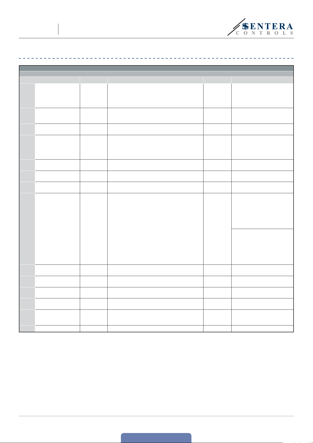
MODBUS REGISTER MAPS
INPUT REGISTERS
Data type Description Data Values
1 Analog input level unsigned int.
2 Current output voltage unsigned int. Actual output voltage
3 Analog input type unsigned int. Type of the selected analog input 0—1
4
5
6
7 Enable off level unsigned int. Enables off level 0—1
8 Off level value unsigned int.
9 Kick star t/soft star t unsigned int. Selects kick start or soft star t 0—1
10 Remote control input unsigned int. Remote control input 0—1
12 L1 c ont rol unsigned int. L1 c ont rol 0 —1
13 Alarm LED unsigned int. Alarm LED 0—1
14 ON/Stand-by LED unsigned int. ON/Stand-by LED 0—2
15-20 Reserved, retur n 0
Ascending/descending
input mode
Maximum output
voltage
Minimum output
voltage
unsigned int.
unsigned int. Maximum output voltage 75 —100
unsigned int. Minimum output voltage 30 —70
Analog input value depending on the selected analog
input type.
Ascending or descending analog input mode depending
on the selected analog input t ype.
Off level value depending on the selected analog
input type and ascending/descending analog input
mode.
0—100
30 —10 0
60 —100
0—1
0—40
MODBUS REGISTER MAPS
0 =
100 =
0 =
100 =
0 =
0
30 =
100 =
0 =
1 =
0 =
1 =
0 =
1 =
75 =
100 =
30 =
70 =
0 =
1 =
Ascending mode:
0 =
400 =
0 =
200 =
Descending mode:
100 =
60 =
100 =
60 =
0 =
1 =
0 =
1 =
0 =
1 =
0 =
1 =
0 =
1 =
2 =
0 VDC
10,0 VD C
or
0 mA
20,0 mA
0 % Us
30 % Us
100 % Us
0—20 mA
0—10 VDC
10— 0 VDC
0—10 VDC
or
20—0 mA
0—20 mA
75 % Us
100 % Us
30 % Us
70 % Us
Disabled
Enabled
Voltage
0 VDC
4,0 VDC
Current
0 mA
8,0 m A
Voltage
10,0 VD C
6,0 V DC
Current
20,0 mA
12, 0 m A
soft star t
kick start
Disabled
Enabled
Off
On
Off
On
Off
On
Stand-by
MIW-EVSS-DM-EN-000 - 18 / 12 / 2018 12 - 16
www.sentera.eu
back to the table of contents
ELECTRONIC FAN SPEED
EVSS
HOLDING REGISTERS
1 Device slave address unsigned int. Modbus device address 1—247 1
2 Modbus baud rate unsigned int. Modbus communication baud rate 1—4 2
3 Modbus parity unsigned int. Parity check mode 0—2 1
4 Device type unsigned int. Device type (Read only)
5 HW version unsigned int. Hardware version of the device (Read only) XXXX 0 x 0300 = HW versio n 3.00
6 FW version unsigned int. Firmware version of the device (Read only) XXXX 0 x 0140 = FW v ersion 1.40
7 Operating mode unsigned int.
8 Output override unsigned int.
9-10 Reserved, r eturn 0
11 Analog input type unsigned int.
Ascending/
12
descending analog
input mode
Maximum output
13
voltage
Minimum output
14
voltage
15 Enable off level unsigned int.
16 Off level value unsigned int.
17 Kic k star t/sof t start unsigned int.
Kick star t/soft star t
18
duration
Remote control
19
functionality
Analog input
20
functionality
21 Operation timer unsigned int.
22-
Reserved, return 0
30
31 Output override value unsigned int.
3240
If you want to find out more about Modbus over serial line, please visit: http://www.modbus.org/docs/Modbus_over_serial_line_V1_02.pdf
CONTROLLER WITH TK
Data type Description Data Default Values
EVSS-DM = 3005
unsigned int.
unsigned int.
unsigned int.
unsigned int.
unsigned int.
unsigned int.
Enables Modbus control and disables the DIP switch
and trimmers
Enables the direct control over the output. Always
settable. Active only if holding register 7 is set to 1.
Selects the analog input type of the device. Always
settable. Active only if holding register 7 is set to 1.
Ascending / descending analog input mode.
Depends on the selected analog input type. Always
settable. Active only if holding register 7 is set to 1.
Maximum settable output voltage. Always
settable. Active only if holding register 7 is set to 1.
Minimum settable output voltage. Always settable.
Active only if holding register 7 is set to 1.
Enables off level. Always set table. Active only if
holding register 7 is set to 1.
Off level value. Depends on the selected analog
input type and ascending / descending analog
input mode. Always settable. Active only if holding
register 7 is set to 1.
Selects kick start or so ft start. Always settable.
Active only if holding register 7 is set to 1.
Sets the duration time. Always settable. Active
only if holding register 7 is set to 1.
Sets the remote control input mode. Depends on
the selected kick start or soft start mode. Always
settable. Active only if holding register 7 is set to 1.
Sets the analog input functionality. Depends on the
selected kick start or soft start. Always settable.
Active only if holding register 7 is set to 1.
Sets the operation time of the device when Timer
mode by remote control input or Logic mode by
the analog input is selected. e operation time
is additional to the kick start/soft start duration
times. Always settable. Active only if holding
registers 7 and 19 or/and 20 are set to 1.
Override value for the analog output. Always
settable. Active only if holding register 8 is set to 1.
Reser ved, return 0
0—1 0
0—1 0
0—1 1
0—1 1
75 —100 100
30 —70 30
0—1 0
0—40
60 —100
0—1 1
0—60 10
0—1 0
0—1 0
0—20 0 60
0
30 —10 0
1 =
2 =
3 =
4 =
0 =
1 =
2 =
0 =
1 =
0 =
1 =
0 =
1 =
0 =
1 =
0 =
1 =
75 =
100 =
30 =
160 =
0 =
1 =
Ascending mode:
0 =
40 =
0 =
0
0
40 =
Descending mode:
100 =
60 =
100 =
60 =
0 =
1 =
0 =
60 =
0 =
1 =
0 =
1 =
0 =
200 =
0 =
30 =
100 =
19.200
38.400
57. 600
Standalone
Modbus mode
Disabled
Enabled
0—20 mA
0—10 VDC
10— 0 V DC
0—10 VDC
20—0 mA
0—20 mA
75 % Us
100 % Us
30 % Us
00 % Us
Disabled
Enabled
Voltage
4,0 VDC
Current
8,0 mA
Voltage
10,0 VD C
6,0 VDC
Current
20,0 mA
12, 0 m A
Sof t star t
Kick star t
Normal mode
Timer mode
Normal mode
Logic mode
0 % Us
30 % Us
100 % Us
9.600
8N1
8E1
8O1
mode
or
0 VDC
0 mA
0 s
60 s
0 s
200 s
MIW-EVSS-DM-EN-000 - 18 / 12 / 2018 13 - 16
www.sentera.eu
back to the table of contents

EVSS
ELECTRONIC FAN SPEED
CONTROLLER WITH TK
INPUT REGISTERS (See Table 1 Modbus register maps)
e input registers are read-only. Table 1 shows how the data is organized in the
input register sector. e measured data starts from address 1 (30001) and ends at
address 14 (30014). e other input registers are not used. When they are addressed,
they return 0.
All the data can be read by “Read Inputs Registers” command. Table1 shows what
the type of the returned data for each register is and the way it should be interpreted.
For example reading ‘300’ in input register 1 means that the measured analog input
signal is 3,0 VDC (or 6,0 mA), reading ‘50’ in input register 2 means that the output
voltage is 50 % Us (115 VAC).
Input register 1 (30001) shows the current value of measured analog input signal.
is value depends on the selected analog input type. When voltage input is
selected, the values vary in the range of 0—1.000 (0—10,0 VDC ). When current input
is selected, the values vary in the range of 0—1.000 (0—20,0 mA).
Input register 2 (30002) shows the current value of the output voltage. is input
register is overridden by holding register 31 if output override control (holding
register 8) is enabled. When output override control is disabled, this input register
shows the value of the output voltage according to the selected operating mode.
e output voltage values vary in the range of 30—100 % Us (69—230 VAC). Reading
‘0’ (0 VAC) indicates that the controller is off.
Input register 3 ( 30003) shows the type of the analog input
signal. is input register is defined by holding register 11 or by the
hardware setting of position 4 of the DIP switch. e values are ‘0’
(for0—20 mA) or ‘1’ (for 0—10 VDC).
Input register 4 ( 30004) shows the selected mode of the analog input. is input
register is defined by holding register 12 or the hardware setting of position 1 of the
DIP switch (Fig. 4), according to the selected operating mode. e values are ‘0’ (for
descending mode) or ‘1’ (for ascending mode).
Input register 5 ( 30005) shows the value of the maximum output voltage. is
input register is defined by holding register 13 or the hardware setting of the Max.
trimmer (Fig. 6), according to the selected operating mode. e register values vary
in range of 75—100 (75—100 % Us VAC).
Input register 6 ( 30006) shows the value of the minimum output voltage. is input
register is defined by holding register 14 or the hardware setting of Min. trimmer
(Fig. 7), according to the selected operating mode. e register values vary in range
30—70 % Us.
Input Register 7 (30007) gives information about the OFF level state. In Standalone
mode it contains the value set by position 2 of the DIP switch (Fig. 4). In Modbus
mode it contains the value of holding register 15. It could be ‘0’ (disabled) or ‘1’
(enabled).
Input Register 8 (30008) gives information about the OFF level value. In
Standalone mode it contains the value set by the OFF level trimmer (Fig. 8).
In Modbus mode it contains the value set by holding register 16. e register
values can vary from 0 to 40 (0—4,0 VDC / 0—8,0 mA) and from 60 to 100
(6,0—10,0 VDC / 12,0—20,0 mA). e values depend on the selected analog input
type and mode.
Input Register 9 (30009) gives information about the kick start or soft start
selection. In Standalone mode the value corresponds to the start type set by position
3 of the DIP switch. In Modbus mode it contains the value set by holding register 17.
e register values are ‘0’ (for soft start) or ‘1’ (for kick start).
Input Register 10 (30010) shows the state of the remote control input. When it is
disabled, the unit works in normal operating mode. When the remote control input is
enabled, the controller is in stand-by mode. e register values are ‘0’ (for disabled)
or ‘1’ (for enabled).
Input Register 11 (30011) shows the status of the alarm relay output. It is off when
the register value is ‘0’, and energised when the register value is ‘1’.
Input Register 12 (30012) shows the status of the unregulated output L1. When
MIW-EVSS-DM-EN-000 - 18 / 12 / 2018 14 - 16
back to the table of contents
www.sentera.eu

EVSS
ELECTRONIC FAN SPEED
CONTROLLER WITH TK
the analog input signal is below the value of the OFF level (if enabled) or when the
remote control input is disabled, the output voltage of the unregulated output L1 is
0 = OFF (0 VAC). Otherwise it is 1 = On (230 VAC).
Input Register 13 (30013) shows the status of the alarm LED (Fig.10). It indicates
motor overheating. When the register value is ‘0’ = Off, there is no overheating and
when the value is ‘1’ = On, the overheating is detected and the controller stops the
motor.
Input Register 14 (30014) shows the operating status of the unit. When the register
value is 0 (Off), the controller is switched off. e ON/Stand-by LED on the front
panel is off. See Fig. 10 Operating indication.
When the value is ‘1’ (On), the controller operates according to the control algorithm,
and the analog input signal is above the selected OFF level value (if enabled). e
ON/Stand-by LED (Fig. 10) gives out continuous light.
e ON/Stand-by LED blinks and the register value is 2 (Stand-by) when OFF level is
enabled and the analog input signal is below the OFF level value.
HOLDING REGISTERS (See Table 1 Modbus register maps)
ese registers are read / write registers and they can be managed with “Read
Holding Registers” command, “Write single register” and “Write Multiple Registers”
commands. ey are organised in parts containing different kind of information. e
holding registers that are not used are read only. Writing values on these registers
does not return Modbus error exception; however, it does not change anything
either!
■
Part 1:
is part contains information about the unit and Modbus communication settings.
Holding register 1 (40001) contains the address at which the controller replies to
the Modbus master unit. e default address is ‘1’. You can change it in two ways:
1. Send command “Write Single Register” with address ‘1’ and write the new
address value.
2. Connec t only your unit to a master controller or PC application and send the
command “Write Single Register” to address ‘0’ (Modbus broadcast address)
and write a new address value.
e next two registers (2 and 3) contain Modbus settings. Changing these registers
you change the communication settings. e default Modbus settings are 19200-E-1
as it is stated in the Modbus Protocol Specification.
e next three registers (4, 5 and 6) are read only. ey contain information about
the hardware and firmware versions.
Holding register 7 (40007) sets the operation mode of the controller. ere are two
options: Standalone mode and Modbus mode. In Standalone mode the controller is
fully controlled by the analog input signal and the selected hardware settings. In
Modbus mode the settings can be controlled by the Modbus master controller.
Holding register 8 (40008) is used for output override control. is setting is used
to override output voltage by a preselected value. is value has greater priority
over the calculated output voltage of the integrated control algorithm. Only kick
star t/soft start can change the output voltage value.
Holding registers 9 (40009) and 10 (40010) are not used. ey are read only.
■
Part 2:
Holding register 11 (40011) sets the analog input signal type. e default value is ‘1’
(0—10 VDC ). ‘0’ is for 0—20 mA.
Holding register 12 (40012) defines the ascending/descending analog input mode.
e default value is ‘1’ is for 0—10 VDC (ascending voltage signal). e register values
are ‘0’ for 10—0 VDC and ‘1’ for 0—10 VDC when voltage signal is selected, and ‘0’
for 20—0 mA and ‘1’ for 0—20 mA when current signal is selected.
Holding register 13 (40013) sets the maximum output voltage. e default value
is ‘100’ (100 % Us or 230 VAC). e register values vary in the range of 75—100
(75—100 % Us).
Holding register 14 (40014) sets the minimum output voltage. e default value is
‘30’ (30 % Us). e register values vary in the range of 30—70 (30—70 % Us).
MIW-EVSS-DM-EN-000 - 18 / 12 / 2018 15 - 16
back to the table of contents
www.sentera.eu

EVSS
ELECTRONIC FAN SPEED
CONTROLLER WITH TK
Holding register 15 (40015) contains the OFF level state. e default value is ‘0’
(disabled). ‘1’ is for enabled.
Holding register 16 (40016) defines the OFF level. is value depends on the
selected analog input type and mode. e register values vary in the ranges of
0—40 (0—4,0 VDC) for ascending voltage signal and 60—100 (6,0—10,0 VDC) for
descending voltage signal. When current signal is selected, the register values are in
ranges of 0—40 (0—8,0 mA) for ascending signal and 60—100 (12,0—20,0 mA) for
descending signal. e default value is ‘0’ (0 VDC).
Holding register 17 (40017) selects kick start or soft start. e default value is ‘1’
(kick start). ‘0’ value is for soft start.
Holding register 18 (40018) contains kick start or soft start duration time. e
default value is ‘10’ (10 seconds). e register values vary from ‘0’ to ‘60’ (0—60
seconds). is setting is accessible only in Modbus mode.
Holding register 19 (40019) selects the remote control input functionality. e
default value is ‘0’ for normal mode. Value ‘1’ is for timer mode. is setting is
accessible only in Modbus mode. OFF level mode is not used in timer mode.
Holding register 20 (40020) selects the analog input functionality. e default value
is ‘0’ for normal mode; ‘1’ is for logic mode. is setting is accessible only in Modbus
mode.
Holding register 21 (40021) contains the value of the operation timer. is holding
register is accessible only in timer mode and/or logic mode. e default value is
‘60’ (60 seconds). e register values can vary from 0 to 200 (0—200 seconds). is
setting is accessible only in Modbus mode. e working time is equal to the sum of
the kick star t/ soft start duration and the time value of the operation timer. When
a working time expires, only a remote control input or analog input can restart the
unit.
e next holding registers 22 (40022)—30 (40030) are not used. ey are read only.
Holding register 31 (40031) overrides the output voltage value in Modbus mode
when output override is enabled. e override value setting does not depend on the
other settings except on the kick start or soft start selection. e default value is
‘0’ (VAC). e register value can vary in the range of 30—100 (30—100 % Us). It can
be also ‘0’ (0 % Us).
e next holding registers 32 (40032)—40 (40040) are not used. ey are read only.
TRANSPORT AND STORAGE
Avoid shocks and extreme conditions; stock in original packing.
WARRANTY AND RESTRICTIONS
Two years from the delivery date against defects in manufactur ing. Any modifications
or alterations to the product after the date of publication relieve the manufacturer
of any responsibilities. e manufacturer bears no responsibility for any misprints or
mistakes in this data.
MAINTENANCE
In normal conditions this product is maintenance-free. If soiled, clean with a dry or
damp cloth. In case of heavy pollution, clean with a non-aggressive product. In these
circumstances the unit should be disconnected from the supply. Pay attention that
no fluids enter the unit. Only reconnect it to the supply when it is completelydry.
MIW-EVSS-DM-EN-000 - 18 / 12 / 2018 16 - 16
back to the table of contents
www.sentera.eu
 Loading...