

SENTERA INTERNET
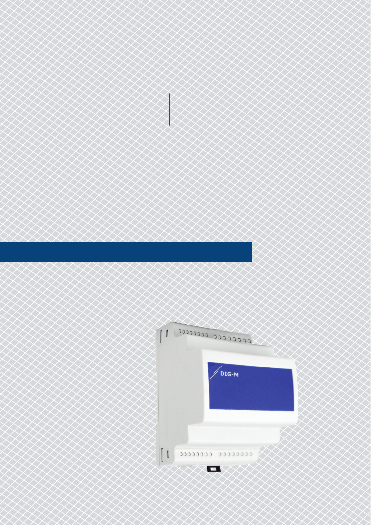
DIG-M
Mounting and operating instructions
GATEWAY
DIN RAIL MOUNTED SENTERA
DIG-M
INTERNET GATEWAY
Table of contents
SAFETY AND PRECAUTIONS 3
PRODUCT DESCRIPTION 4
ARTICLE CODES 4
INTENDED AREA OF USE 4
TECHNICAL DATA 4
STANDARDS 4
WIRING AND CONNECTIONS 5
MOUNTING INSTRUCTIONS IN STEPS 5
VERIFICATION OF THE INSTALLATION INSTRUCTIONS 8
TRANSPORT AND STORAGE 8
WARRANTY AND RESTRICTIONS 8
MAINTENANCE 8
MIW-DIG-M-EN-000 - 22 / 04 / 2019 2 - 8
www.sentera.eu
DIN RAIL MOUNTED SENTERA
DIG-M
INTERNET GATEWAY
SAFETY AND PRECAUTIONS
Read all the information, the datasheet, mounting and operating instructions and
study the wiring and connection diagram before working with the product. For
personal and equipment safety, and for optimum product performance, make sure you
entirely understand the contents before installing, using, or maintaining this product.
For saf ety and li censing (CE ) reasons , unauthor ised conver sion and/ or modific ations
of the product are inadmissible.
e product should not be exposed to abnormal conditions, such as: extreme
temperatures, direct sunlight or vibrations. Long-term exposure to chemical
vapours in high concentration can affect the product performance. Make sure the
work environment is as dry as possible; avoid condensation.
All installations shall comply with local health and safety regulations and local
electrical standards and approved codes. is product can only be installed by
an engineer or a technician who has expert knowledge of the product and safety
precautions.
Avoid contacts with energised electrical parts. Always disconnect the power
supply before connecting, servicing or repairing the product.
Always verify that you apply appropriate power supply to the product and use
appropriate wire size and characteristics. Make sure that all the screws and nuts
are well tightened and fuses (if any) are fitted well.
Recycling of equipment and packaging should be taken into consideration and these
should be disposed of in accordance with local and national legislation/regulations.
In case there are any questions that are not answered, please contact our technical
support or consult a professional.
MIW-DIG-M-EN-000 - 22 / 04 / 2019 3 - 8
back to the table of contents
www.sentera.eu

DIN RAIL MOUNTED SENTERA
DIG-M
INTERNET GATEWAY
PRODUCT DESCRIPTION
ARTICLE CODES
DIG-M is a Modbus RTU - Internet gateway intended for connecting Sentera devices to
the Internet in order to monitor and configure them via the Sentera Web Server interface.
INTENDED AREA OF USE
TECHNICAL DATA
Code
DIG-M 24 VDC (PoM)
■
Data logging via the Sentera Web Server interface
■
Modify Modbus parameters via the Sentera Web Server interface
■
Firmware update of Sentera devices
■
Download application dedicated firmware
■
24 VDC / 1 W supply voltage, Power over Modbus (PoM)
■
Maximum power consumption: 0,4 W
■
Output voltage for connecting slave devices: 24 VDC
■
Easy to connect via two Modbus RTU RJ45 connectors (one Master and one
slave channel)
■
Can be connected to the Internet via WLAN (Wi-Fi) or LAN (Ethernet cable)
■
DIN rail mounted
■
Enclosure: plastic ABS, UL94-V0, grey R AL 7035
■
Protection class: IP20
■
Operating ambient conditions:
►
Temperature: -10—50 °C
►
Rel. humidity: 5—85 % rH (non-condensing)
Supply voltage
STANDARDS
■
EMC directive 2014/30/EU:
►
EN 61000-6-1:2007 Electromagnetic compatibility (EMC) - Part 6-1: Generic
standards - Immunity for residential, commercial and light-industrial
environments
►
EN 61000-6-3:2007 Electromagnetic compatibility (EMC) - Par t 6-3: Generic
standards - Emission standard for residential, commercial and light-industrial
environments Amendments A1:2011 and AC:2012 to EN 61000-6-3
►
EN 55032:2012 Electromagnetic compatibility (EMC) of multimedia equipment
- Emission requirements Amendment AC:2013 to EN 55032
►
CISPR 32:2012
►
EN 50561-1:2013 Power line communication apparatus used in low-voltage
installations – Radio disturbance characteristics – Limits and methods of
measurement – Part 1: Apparatus for in-home use
■
WEEE 2012 / 19/EC
■
RoHs Directive 2011/65/EC
MIW-DIG-M-EN-000 - 22 / 04 / 2019 4 - 8
back to the table of contents
www.sentera.eu

1
70,10
DIN RAIL MOUNTED SENTERA
DIG-M
INTERNET GATEWAY
WIRING AND CONNECTIONS
Pin 1
Pin 2
Pin 3
Pin 4
Pin 5
Pin 6
Pin 7
Pin 8
RJ45 sockets (Power over Modbus)
24 VDC Supply voltage
A Modbus RTU communication, signal A
/B Modbus RTU communication, signal /B
GND Ground, supply voltage
8 mm
24 VDC
GND
2
3
8 mm
4
A
5
8 mm
6
/B
7
8 mm
8
RJ45
1
2
3
4
5
6
7
8
MOUNTING INSTRUCTIONS IN STEPS
Before you start mounting the DIG-M, read carefully “Safety and Precautions” and
follow these steps:
1. Slide the unit along the guides of a standard 35 mm DIN rail and fix it to the rail
by means of the black locking clip on the enclosure. Mind the correct position and
mounting dimensions shown in Fig. 1 Mounting dimensions and Fig. 2 Mounting
position.
Fig. 1 Mounting dimensions
Bottom view Top view Front view
Side view Side view Rear view
92,11
35,30
65,8
MIW-DIG-M-EN-000 - 22 / 04 / 2019 5 - 8
www.sentera.eu
back to the table of contents

DIG-M
Fig. 2 Mounting position
DIN RAIL MOUNTED SENTERA
INTERNET GATEWAY
DIN rail
DIG-M
ATTENTION
Fig. 3 Wiring
Ethernet
Locking clip
2. Connec t the Sentera slave devices via Modbus RTU on the lef t RJ45 socket.
3. If applicable, the BMS or external Modbus RTU master can be connected via the
right RJ45 socket.
4. e DIG-M unit needs PoM (24 VDC). So either, the Slave or Master channel must
be powered with 24 VDC.
Do not connect both circuits with PoM 24 VDC power supply simultaneously!
Locked
Unlocked
Top view - RJ45 Ethernet connection
vt
Bottom view - RJ45 PoM: Modbus RTU and 24 VDC
power supply
PoM Slave PoM Master
5. Connect DIG-M to the internet via WLAN ( Wi-Fi) or LAN (Ethernet cable). For
more information, consult the DIG-M user guide via the Sentera website.
MIW-DIG-M-EN-000 - 22 / 04 / 2019 6 - 8
www.sentera.eu
back to the table of contents

DIN RAIL MOUNTED SENTERA
DIG-M
Example 1 Example 2
Slave 1
INTERNET GATEWAY
NBT
NBT
Slave 2
Master
Optional settings
If your unit starts or terminates the network (see Example 1 and Example2), enable
the NBT resistor via 3SModbus. If your device is not an end device, leave the NBT
disabled (default Modbus setting).
RX
ТX
NBT
Slave n
Master
RX
NBT
Slave 1
Slave 2
ТX
NBT
Slave n
NOTE
Connect the NBT terminator only in the two most distant units on the network line!
Bootloader
anks to the bootloader functionality, the device firmware is updated via Modbus RTU
communication. To enter ‘Boot mode”, put a jumper onto pins 3 and 4 of the P1 header
and restar t the power supply (see Fig. 4). Once ‘Boot mode’ is activated, the firmware
can be updated via SM Boot application (part of 3SModbus software suite).
Fig. 4 P1 header
Put a jumper onto pins 1 and 2 and
123 45
wait for at least 5 seconds to reset the
Modbus communication parameters
Put a jumper onto pins 3 and 4 and restar t
123 45
the supply to enter bootloader mode
Reset button
Press and hold the button for 2 seconds to reset the DIG-M device to its default
values (Default Static-IP: 192.168.1.123, Default Connection Type: Ethernet, Default
Connection Mode: DHCP).
Fig. 5 Reset button
MIW-DIG-M-EN-000 - 22 / 04 / 2019 7 - 8
www.sentera.eu
back to the table of contents

DIN RAIL MOUNTED SENTERA
DIG-M
INTERNET GATEWAY
VERIFICATION OF THE INSTALLATION INSTRUCTIONS
■
Green LED1 indicates that the unit is supplied and that the Modbus RTU
communication with slave devices is ac tive.
■
Green LED2 indicates active communication with the Internet. i.e. DIG-M
successfully communicates with the Sentera Web-Server sending parameters
to the Cloud.
■
Slowly blinking red LED3 indicates system error (connection to the Cloud has
been lost).
■
Fast blinking LED3 indicates that bootloader mode has been entered (see Fig. 6).
■
Blinking LEDs on the RJ45 sockets indicate that packages are transmitted via
Modbus RTU.
■
If this is not the case, check the connections.
Fig. 6 LED indications
LED 1LED 3 LED 2
ATTENTION
e status of the LEDs can be checked only when the unit is energised. Take the
relevant safety measures!
TRANSPORT AND STORAGE
Avoid shocks and extreme conditions; stock in original packing.
WARRANTY AND RESTRICTIONS
Two years from the delivery date against defects in manufacturing. Any modifications
or alterations to the product after the date of publication relieve the manufacturer
of any responsibilities. e manufacturer bears no responsibility for any misprints or
mistakes in this data.
MAINTENANCE
In normal conditions this product is maintenance-free. If soiled, clean with a dry or
damp cloth. In case of heavy pollution, clean with a non-aggressive product. In these
circumstances the unit should be disconnec ted from the supply. Pay attention that
no fluids enter the unit. Only reconnect it to the supply when it is completelydr y.
MIW-DIG-M-EN-000 - 22 / 04 / 2019 8 - 8
back to the table of contents
www.sentera.eu
 Loading...