

Sentera STR-4 series, STR-4-15L40, STR-4-25L40, STR-4-40L40, STR-4-60L40 Mounting And Operating Instructions
...
Mounting and operating instructions
STANDARD 3-PHASE 400 VAC
TRANSFORMER CONTROLLER
STR-4
www.sentera.eu
MIW-STR-4-EN-000 - 09 / 08 / 2018 2 - 8
Table of contents
SAFETY AND PRECAUTIONS 3
PRODUCT DESCRIPTION 4
ARTICLE CODES 4
INTENDED AREA OF USE 4
TECHNICAL DATA 4
STANDARDS 4
OPERATIONAL DIAGRAMS 5
WIRING AND CONNECTIONS 5
MOUNTING AND OPERATING INSTRUCTIONS IN STEPS 5
VERIFICATION OF INSTALLATION 8
TRANSPORT AND STORAGE 8
WARRANTY AND RESTRICTIONS 8
MAINTENANCE 8
STANDARD 3-PHASE 400 VAC
TRANSFORMER CONTROLLER
STR-4
www.sentera.eu
MIW-STR-4-EN-000 - 09 / 08 / 2018 3 - 8
back to the table of contents
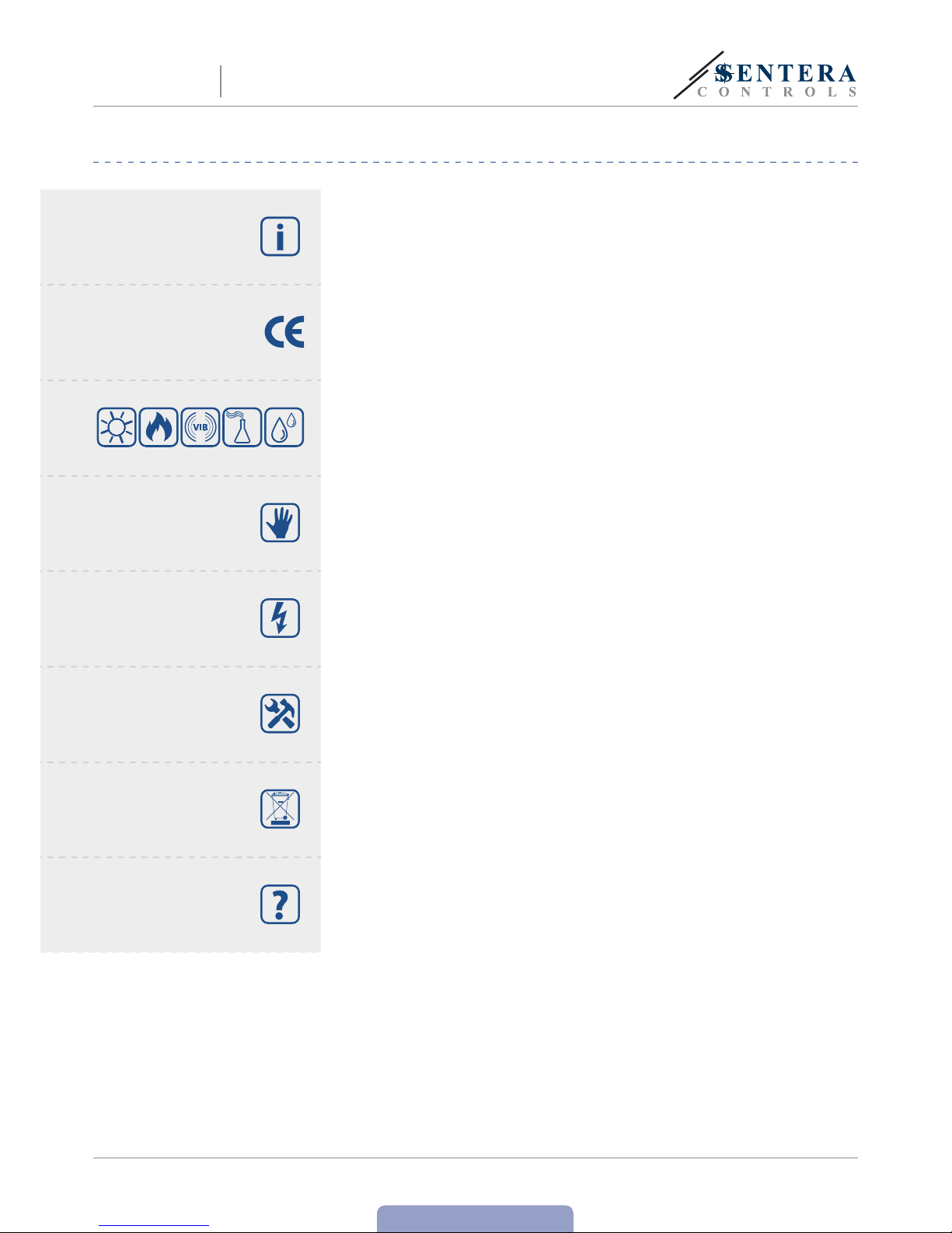
SAFETY AND PRECAUTIONS
Read all the information, the datasheet, mounting and operating instructions and
study the wiring and connection diagram before working with the product. For
personal and equipment safety, and for optimum product performance, make sure you
entirely understand the contents before installing, using, or maintaining this product.
For saf ety and lic ensing (CE ) reasons , unauthor ised conver sion and/ or modific ations
of the product are inadmissible.
e product should not be exposed to abnormal conditions, such as: extreme
temperatures, direct sunlight or vibrations. Long-term exposure to chemical
vapours in high concentration can affect the produc t per formance. Make sure the
work environment is as dry as possible; avoid condensation.
All installations shall comply with local health and safety regulations and local
electrical standards and approved codes. is product can only be installed by an
engineer or a technician who has expert knowledge of the product and safety
precautions.
Avoid contacts with energised electrical parts. Always disconnect the power
supply before connecting, servicing or repairing the product.
Always verify that you apply appropriate power supply to the product and use
appropriate wire size and characteristics. Make sure that all the screws and nuts
are well tightened and fuses (if any) are fitted well.
Recycling of equipment and packaging should be taken into consideration and these
should be disposed of in accordance with local and national legislation/regulations.
In case there are any questions that are not answered, please contact your
technical support or consult a professional.
STANDARD 3-PHASE 400 VAC
TRANSFORMER CONTROLLER
STR-4

www.sentera.eu
MIW-STR-4-EN-000 - 09 / 08 / 2018 4 - 8
back to the table of contents
PRODUCT DESCRIPTION
e STR-4 series of transformer fan speed controllers regulate the rotational speed
of three-phase voltage controllable motors by varying the output voltage. ey are
equipped with auto-transformers and control the speed manually in five steps. e
used technology provides a regulated output voltage with a perfect sinusoidal shape.
ARTICLE CODES
Article code Rated max. current [A]
STR-4-15L40 1,5
STR-4-25L40 2,5
STR-4-40L40 4,0
STR-4-60L40 6,0
STR-4-80L40 8,0
STR-4110L40 11,0
STR-4140L50 14,0
INTENDED AREA OF USE
■
Speed control of voltage controllable 400 VAC three-phase motors (pumps and
fans)
■
For indoor use only
TECHNICAL DATA
■
Supply voltage: 3x 400 VAC / 50—60 Hz
■
Maximum motor current (Imax): depends on the version (see ar ticle codes)
■
Unregulated output: 230 VAC
■
Wide power range
■
5-step rotar y switch for manual control plus off-position
■
LED status indication
■
Enclosure: sheet steel (RAL 7035, polyester powder coating)
■
Protection standard: IP54 (according to EN 60529)
■
Operating ambient conditions:
►
Temperature: -20—35 °C
►
Rel. humidity: 5—95 % rH (non-condensing)
STANDARDS
■
Low Voltage Directive 2014/35/EC
EMC Directive 2014/30/EC: EN 61326
■
WEEE D i r e c tive 2012/19/ EC
■
RoHs Directive 2011/65/EC
STANDARD 3-PHASE 400 VAC
TRANSFORMER CONTROLLER
STR-4

www.sentera.eu
MIW-STR-4-EN-000 - 09 / 08 / 2018 5 - 8
back to the table of contents
OPERATIONAL DIAGRAMS
L50 series L40 series
Knob position
0123 45
400
300
260
220
230 VA
C
170
U [VAC]
L1
Regulated output (U)
Unregulated output (L1)
0123 45
400
300
230
180
130
U [VAC]
L1
Knob
position
Regulated output (U)
Unregulated output (L1)
WIRING AND CONNECTIONS
Connections
Pe Earth terminals
R
Power supply (3x 400 VAC / 50—60 Hz)S
T
N Power supply & unregulated output, Neutral
L1 Unregulated output, phase (230 VAC / 50—60 Hz / 2 A)
U
Regulated output to motorV
W
ATTENTION
Make sure you use cables with an appropriate diameter.
MOUNTING AND OPERATING INSTRUCTIONS IN STEPS
Before you start mounting the STR-4, read carefully “Safety and Precautions” and
follow these steps. Choose a smooth solid surface for installation (a wall, panel, etc.).
Follow these steps:
1. Open the door of the controller. Mind the wires that connect the rotar y switch
with the autotransformer.
2. Mount the enclosure using corrosion resistant screws or bolts. Mind the correct
mounting position and unit mounting dimensions (see Fig. 1 Mounting dimensions
and Fig. 2 Mounting position). e mounting holes are on the inside back panel of
the enclosure and are covered with blanking plugs.
STANDARD 3-PHASE 400 VAC
TRANSFORMER CONTROLLER
STR-4

www.sentera.eu
MIW-STR-4-EN-000 - 09 / 08 / 2018 6 - 8
back to the table of contents
3. Pay attention to following instructions in order to minimize the operating
temperature:
3.1 Respect the distances both between the wall / ceiling and the device
and between two devices as shown in Fig. 2. In order to ensure sufficient
ventilation of the controller, clearance on every side has to be maintained.
3.2 When installing the device, please keep in mind that the higher you install it,
the warmer the device will get. For example, in a technical room the correct
installation height can be of great importance.
3.3 If maximum ambient temperature cannot be adhered to, please provide
extra forced ventilation / cooling.
Not respecting the abovelisted rules can reduce service life and relieves the
manufacturer of any responsibilities.
4. Once secured in position, the mounting screws or bolts should be sealed to
maintain the IP rating of the enclosure.
5. Because the controller enclosure is made of metal, it must be earthed and bonded
to other existing metal surfaces.
Fig. 1 Mounting dimensions Fig. 2 Mounting position
A
C
B
E
D
Correct Incorrect
50 mm 50 mm
75 mm
50 mm
1
3
2
4
Article code
A
[mm]
B
[mm]
C
[mm]
D
[mm]
E
[mm]
STR-4-15L40
300 325 185 255 255
STR-4-25L40
300 325 185 255 255
STR-4-40L40
300 425 185 255 355
STR-4-60L40
300 425 235 255 355
STR-4-80L40
300 425 235 255 355
STR-4110L40
400 430 235 355 355
STR-4140L50
400 430 235 355 355
6. Insert the cables through the cable glands and do the wiring according to the
wiring diagram (see Fig. 3) while adhering to the information from section
“Wiring and connections” above.
6.1 Connect the power supply lines (terminals R, S, T, N and PE);
6.2 Connec t the motor(s) (terminals U, V, W and PE);
6.3 If applicable, connect the unregulated output (L1 and N). It can be used to
supply a 230 VAC valve, lamp, etc. when the knob is not at ‘0’ position (see
Tabl e 1 below).
ATTENTION
A safety isolator / disconnect switch should be installed on the mains electricity
side of all motor drives.
ATTENTION
e earth wire (green-yellow) of the electrical supply and of any equipment
connected to the controller must be connected to the terminals marked as PE.
STANDARD 3-PHASE 400 VAC
TRANSFORMER CONTROLLER
STR-4

www.sentera.eu
MIW-STR-4-EN-000 - 09 / 08 / 2018 7 - 8
back to the table of contents
Fig. 3 Wiring and connections
RST NL1 UVW
3 x 400 Vac
230 Vac
3ph + N
ATTENTION
All works must be carried out with equipment fully isolated from the power
supply.
ATTENTION
Make sure the connections are correct before you power the unit.
7. Close the cover.
8. Turn the knob at ‘0’.
9. Tighten the cable glands.
10. Switch on the mains supply.
11. Make sure the transformer controller can operate normally (consider an isolating
switch).
12. Turn the knob into the relevant position to adjust the output voltage.
Optional settings
e standard configuration of the output voltages is as indicated in Table 1 below.
However, if more than 5 output voltages are available, it is possible to adjust the 5
steps by changing the internal wiring.
Table 1 Voltage series
Knob position 0 - 1 2 3 4 5
Regulated output [VAC]
L40 version 0 - 130 18 0 230 300 400
L50 version 0 130 * 170 220 260 300 400
Unregulated output [VAC]
L1 0 230 230 230 230 230 230
* Available but not connected.
STANDARD 3-PHASE 400 VAC
TRANSFORMER CONTROLLER
STR-4

www.sentera.eu
MIW-STR-4-EN-000 - 09 / 08 / 2018 8 - 8
back to the table of contents
STANDARD 3-PHASE 400 VAC
TRANSFORMER CONTROLLER
STR-4
VERIFICATION OF INSTALLATION
ATTENTION
Use only tools and equipment with non-conducting handles when working on
electrical devices.
After connecting the unit to the mains supply, the green LED on its cover should
light up indicating that the controller is supplied.
Safe operation depends on proper installation. Before start up, ensure the following:
■
e mains supply is connected correc tly.
■
Protection is provided against electrical shock.
■
e cables are the appropriate size and fuse-protected.
■
ere is sufficient air flow around the unit.
ATTENTION
e unit is supplied with electrical energy at voltages high enough to inflict personal
injury or threat to health. Take the relevant safety measures.
ATTENTION
Disconnect and confirm that there is no live current flowing to the unit before servicing.
ATTENTION
Avoid exposing the controller to direct sunlight!
TRANSPORT AND STORAGE
Avoid shocks and extreme conditions; stock in original packing.
WARRANTY AND RESTRICTIONS
Two years fr om the delivery da te against defec ts in manufactu ring. Any modifica tions
or alterations to the product af ter the date of publication relieve the manufac turer
of any responsibilities. e manufacturer bears no responsibility for any misprints or
mistakes in this data.
MAINTENANCE
In normal conditions this product is maintenance-free. If soiled, clean with a dry or
damp cloth. In case of heavy pollution, clean with a non-aggressive product. In these
circumstances the unit should be disconnected from the supply. Pay attention that
no fluids enter the unit. Only reconnec t it to the supply when it is completelydry.
 Loading...