

Sentera STL Series, STL-0-30-AT, STL-0-60-AT, STL-0-15-AT, STL-0-50-AT Mounting And Operating Instructions
...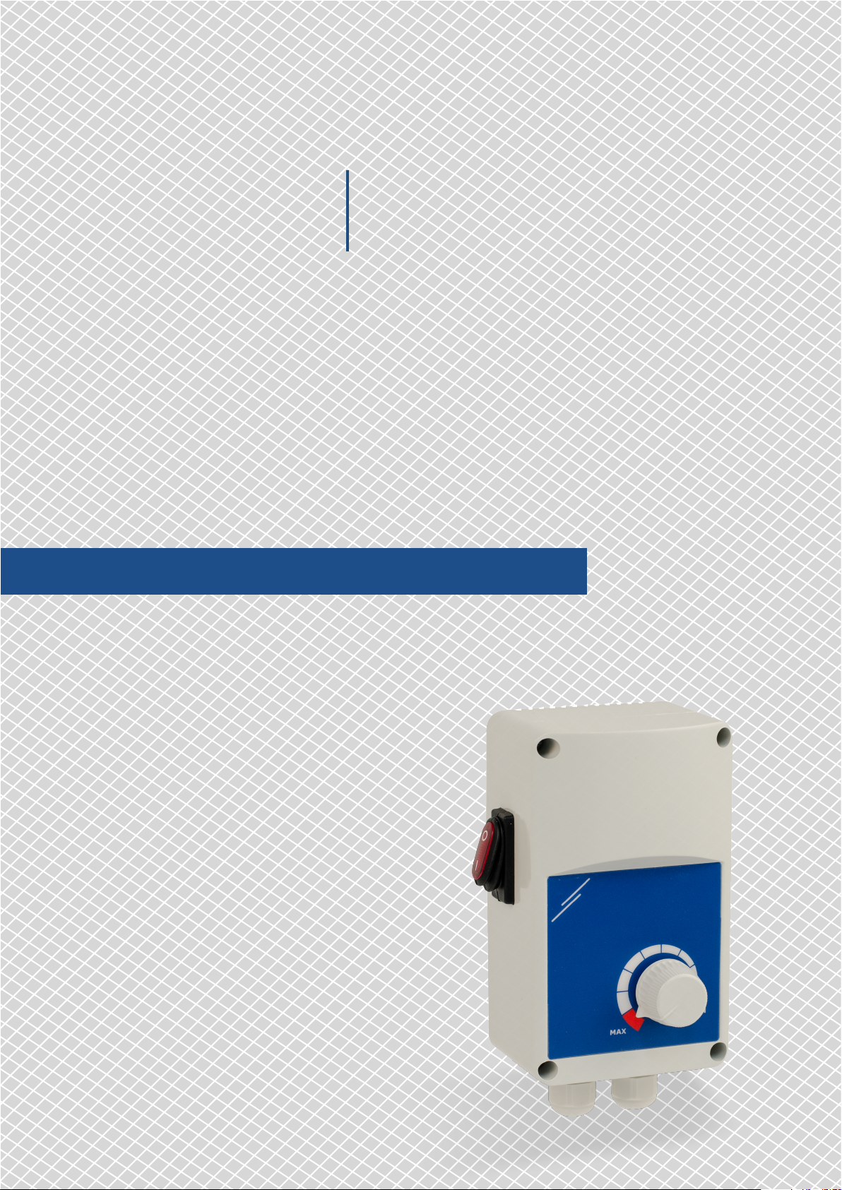
ELECTRONIC FAN SPEED
STL
Mounting and operating instructions
CONTROLLER, 230 VAC
ELECTRONIC FAN SPEED
STL
CONTROLLER, 230 VAC
Table of contents
SAFETY AND PRECAUTIONS 3
PRODUCT DESCRIPTION 4
ARTICLE CODES 4
INTENDED AREA OF USE 4
TECHNICAL DATA 4
STANDARDS 5
WIRING AND CONNECTIONS 5
OPERATIONAL DIAGRAMS 5
MOUNTING INSTRUCTIONS IN STEPS 5
VERIFICATION OF INSTALLATION INSTRUCTIONS 7
TRANSPORT AND STORAGE 8
WARRANTY AND RESTRICTIONS 8
MAINTENANCE 8
MIW-STL-EN-002 - 30 / 07 / 2018 2 - 8
www.sentera.eu
ELECTRONIC FAN SPEED
STL
CONTROLLER, 230 VAC
SAFETY AND PRECAUTIONS
Read all the information, the datasheet, mounting and operating instructions and
study the wiring and connection diagram before working with the product. For
personal and equipment safety, and for optimum product performance, make sure you
entirely understand the contents before installing, using, or maintaining this product.
For safety and licensing (CE) reasons, unauthor ised conversion and/ or modifications
of the product are inadmissible.
e product should not be exposed to abnormal conditions, such as: extreme
temperatures, direct sunlight or vibrations. Long-term exposure to chemical
vapours in high concentration can affect the product performance. Make sure the
work environment is as dry as possible; avoid condensation.
All installations shall comply with local health and safety regulations and local
electrical standards and approved codes. is product can only be installed by an
engineer or a technician who has expert knowledge of the product and safety
precautions.
Avoid contacts with energised electrical parts. Always disconnect the power
supply before connecting, servicing or repairing the product.
Always verify that you apply appropriate power supply to the product and use
appropriate wire size and charac teristics. Make sure that all the screws and nuts
are well tightened and fuses (if any) are fitted well.
Recycling of equipment and packaging should be taken into consideration and these
should be disposed of in accordance with local and national legislation/regulations.
In case there are any questions that are not answered, please contact your
technical support or consult a professional.
MIW-STL-EN-002 - 30 / 07 / 2018 3 - 8
back to the table of contents
www.sentera.eu

ELECTRONIC FAN SPEED
STL
CONTROLLER, 230 VAC
PRODUCT DESCRIPTION
ARTICLE CODES
e STL electronic speed controllers regulate the speed of single-phase (230VAC /
50Hz) voltage controllable motors by varying the supplied voltage. e output is
regulated by a potentiometer and the admissible minimum speed can be adjusted
by a trimmer (factory preset to 100 VAC). ey feature an unregulated output for
connecting a valve, lamp, damper, etc. ere are two start-up modes, kick start and
soft start, selectable by placing or removing a jumper on the PCB. When kick start
mode is selected, the motor starts (or restarts) at maximum speed for 8—10 seconds,
then the motor speed automatically follows the position of the potentiometer.
When normal start mode is selected, the motor starts according to the position of
the potentiometer.
Code Rated max. current [A] Fuse rating [A]
STL-0-15-AT 1,5 F-3,15 A-H
STL-0-30-AT 3,0 F-5,00 A-H
STL-0-50-AT 5,0 F-8,00 A-H
STL-0-60-AT 6,0 F-10,00 A-H
STL-0100-AT 10,0 F-16,00 A- H
INTENDED AREA OF USE
TECHNICAL DATA
■
Fan speed control of voltage controllable motors in ventilation systems
■
For indoor use only
■
Power supply: 230 VAC ±10 %/50 Hz
■
Regulated output: max. current rating depending on the version
■
Unregulated output: 230 VAC / 50 Hz(max. 2 A)
■
Min. voltage output: 80—170 VAC, selectable by trimmer
■
Kick start or normal start, selectable by a jumper on the PCB
■
Illuminated ON / OFF rocker switch
■
Enclosure:
►
plastic R-ABS, UL94-V0
►
grey colour (RAL 7035)
■
Protection standard: IP54 (according to EN 60529)
■
Operating ambient conditions:
►
temperature: 0—35 °C
►
rel. humidity: < 95 % rH (non-condensing)
■
Storage temperature: -40—50 °C
MIW-STL-EN-002 - 30 / 07 / 2018 4 - 8
back to the table of contents
www.sentera.eu

Vout [VAC]
8—10 s
Vout [VAC]
]
ELECTRONIC FAN SPEED
STL
CONTROLLER, 230 VAC
STANDARDS
■
Low Voltage Directive 2006/95/EC
■
EMC Directive 2004/108/EC: EN 61326
■
WEE E Di r ective 2012/19/EU
■
RoHs Directive 2011/65/EU
WIRING AND CONNECTIONS
L Power supply, phase 230 VAC / 50 Hz
N Power supply, neutral
L1 Unregulated output (230 VAC/max. 2 A)
PE Earth terminal
M Regulated output, phase
N Regulated output, neutral
Connections
Cable cross section: max. 2,5 mm
2
Cable gland clamping range: 5—10 mm/ 8—13 mm (STL-0100-AT)
OPERATIONAL DIAGRAMS
Kick start mode Normal start mode
230 VAC
Minimum
speed
External potentiometer value
0
t [s]
230 VAC
Minimum
speed
0
MOUNTING INSTRUCTIONS IN STEPS
Before you start mounting the STL read carefully “Safety and Precautions”.
Choose a smooth surface for installation (a wall, panel and etc).
Follow these steps:
External potentiometer value
t [s
1. Make sure the STL controller is switched off and the power is disconnected.
2. Unscrew the front cover and open the enclosure. Mind the two wires that
connect the potentiometer with the printed circuit board.
MIW-STL-EN-002 - 30 / 07 / 2018 5 - 8
back to the table of contents
www.sentera.eu

ELECTRONIC FAN SPEED
STL
Fig. 1 Mounting dimensions Fig. 2 Mounting position
CONTROLLER, 230 VAC
3. Fix the unit to the wall or panel using the provided screws and dowels. Mind the
correct mounting position and unit mounting dimensions (seeFig. 1 and Fig. 2).
F
B
A
C
Article code A B C D E F
STL-0-15-AT
STL-0-30-AT
STL-0-50-AT 162 mm 96 mm 93 mm 71 mm 108,8 mm Ø 4,2
STL-0-60-AT
STL-0100-AT
162 mm 96 mm 75 mm 71 mm 108,8 mm Ø 4,2
205 mm 124 mm 97 mm 102 mm 140 mm Ø 4,6
D
E
4. Insert the cables through the cable glands and do the wiring according to the
wiring diagram (see Fig. 3) using the information from section “Wiring and
connections”.
4.1 Connect the motor/fan.
4.2 Connect L1 if you want to use a lamp, valve, damper, etc. (for 3-wire
connection). L1 is powered while the regulated output is active and
connecting an item to it is optional.
4.3 Connect the power supply and earth terminals.
Correct Incorrect
Fig. 3 Wiring and connections
Power supply
230 VAC ±10 % / 50 Hz
Unregulated output
230 VAC / max . 2 A
ATTENTION
ATTENTION
L
N
N
L1
Single-phase motor connection
Make sure that you use cables with an appropriate diameter.
Make sure that the connections are correct before you power the unit.
5. Set the potentiometer at Min. speed position and switch on the controller.
MIW-STL-EN-002 - 30 / 07 / 2018 6 - 8
www.sentera.eu
back to the table of contents

STL
ELECTRONIC FAN SPEED
CONTROLLER, 230 VAC
6. Using a screwdriver, adjust the minimum speed trimmer (if necessary). e
7. Select “kick start” or “normal start” using the jumper shown in Fig. 6 Kick start
Fig. 4 Min. speed trimmer Fig. 5 Kick start jumper
8. Put back the cover and secure it with the screws.
9. Star t the power supply and turn on the STL by pressing the illuminated rocker
factory setting is 100 VAC, see Fig. 4 Min. speed trimmer. Adjusting the trimmer
to the desired minimum output value ensures that the motor will continue
operarting or restart smoothly in case of power faults.
ju mpe r. Kick start duration is 8—10 s. By default the jumper is connected, i.e. the
pre-set mode is “kick start”. Keep the jumper installed or remove it depending on
your start mode selection.
Kick s tart is ena bled ( jumper
*
Kick s tart sele ctio n
jumper JP1
connected)
Kick s tart is dis abled ( jumper
disconnected)
switch.
VERIFICATION OF INSTALLATION INSTRUCTIONS
ATTENTION
Use only tools and equipment with non-conducting handles when working on
electrical devices.
Make sure that the motor runs at maximum speed for 8—10 seconds. After this
period, it will operate according to the potentiometer position.
If this is not the case, check the connections and the settings again.
■
In case of faulty operation, please check if:
►
the correct output voltage has been set via the potentiometer;
►
the trimmer has been set in the desired position;
►
all connections are correct;
►
the regulated device is functioning.
MIW-STL-EN-002 - 30 / 07 / 2018 7 - 8
www.sentera.eu
back to the table of contents

ELECTRONIC FAN SPEED
STL
CONTROLLER, 230 VAC
TRANSPORT AND STORAGE
Avoid shocks and extreme conditions; stock in original packing.
WARRANTY AND RESTRICTIONS
Two years from the delivery date against defects in manufactur ing. Any modifications
or alterations to the product after the date of publication relieve the manufacturer
of any responsibilities. e manufacturer bears no responsibility for any misprints or
mistakes in this data.
MAINTENANCE
In normal conditions this product is maintenance-free. If soiled, clean with a dr y or
damp cloth. In case of heavy pollution, clean with a non-aggressive product. In these
circumstances the unit should be disconnected from the supply. Pay attention that
no fluids enter the unit. Only reconnect it to the supply when it is completelydry.
ATTENTION
Use only fuses with type and rating specified above; otherwise, loss of warranty
will ensue.
MIW-STL-EN-002 - 30 / 07 / 2018 8 - 8
back to the table of contents
www.sentera.eu
 Loading...