

Page 1
Pilot’s Operating Handbook
PHX
Unmanned Aircraft
Version 1.2
Sentera, LLC
6636 Cedar Ave, Minneapolis, MN 55423, USA
Page 2

This page intentionally blank
Page 3

REVISION HISTORY
Version
Description
Date
0.1
DRAFT - Initial Release
14 July, 2017
0.2
DRAFT - Release
03 August, 2017
0.3
DRAFT - Release
12 September, 2017
0.4
DRAFT – Release
11 January, 2018
0.5
DRAFT – Release
18 January, 2018
0.6
DRAFT – Release
09 March, 2018
1.0
Official – Release
13 August, 2018
1.1
Official - Release
16 August, 2018
1.2
Official – Release
13 September, 2018
Page 4

i
CONTENTS
SECTION 1: GENERAL .................................................................................................................... 1-1
INTRODUCTION ................................................................................................................................. 1-1
3-VIEW DRAWING ............................................................................................................................. 1-1
ACRONYMS, ABBREVIATIONS, SYMBOLS, AND TERMINOLOGY ..................................... 1-2
UAS TERMS: ................................................................................................................................... 1-2
AIRCRAFT TERMS: ....................................................................................................................... 1-2
AVIATION TERMS: ......................................................................................................................... 1-2
USER INTERFACE TERMS:......................................................................................................... 1-3
SECTION 2: LIMITATIONS .............................................................................................................. 2-1
SECTION 3: EMERGENCY PROCEDURES ................................................................................. 3-1
LOSS OF PROPULSION .................................................................................................................. 3-1
GCS SOFTWARE CRASH OR LOCK-UP ..................................................................................... 3-1
LOST LINK .......................................................................................................................................... 3-1
Aircraft autonomous behavior during lost link ..................................................................... 3-2
Aircraft autonomous behavior during lost GPS: .................................................................. 3-2
SECTION 4: NORMAL PROCEDURES ......................................................................................... 4-1
FLIGHT PLANNING IN SENTERA GROUND CONTROL SOFTWARE .................................. 4-1
PRE-FLIGHT ACTIVITIES ................................................................................................................ 4-7
AIRSPEED CALIBRATION .............................................................................................................. 4-8
MAGNETIC COMPASS CALIBRATION ........................................................................................ 4-9
CHECKLISTS .................................................................................................................................... 4-10
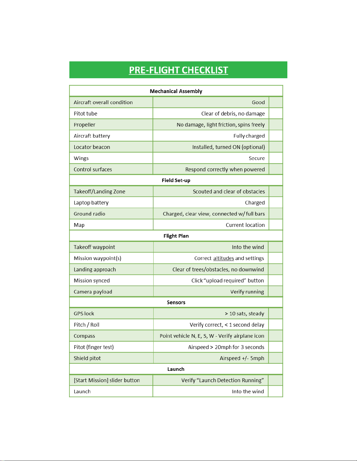
EXAMPLE PRE-FLIGHT CHECKLIST ..................................................................................... 4-11
DURING FLIGHT AIRCRAFT STATUS SCAN ....................................................................... 4-12
LANDING PROCEDURE ............................................................................................................. 4-12
LAUNCH TECHNIQUE .................................................................................................................... 4-12
LANDING TECHNIQUE ................................................................................................................... 4-14
ADVANCED PLANNING FOR LANDING PATTERNS .............................................................. 4-14
SECTION 5: PERFORMANCE ...................................................................................................... 5-15
PERFORMANCE CHARACTERISTICS ....................................................................................... 5-15
SECTION 6: WEIGHT AND BALANCE ......................................................................................... 6-1
WEIGHT ............................................................................................................................................... 6-1
CENTER OF GRAVITY ...................................................................................................................... 6-1
Page 5

ii
SECTION 7: SYSTEM DESCRIPTION ........................................................................................... 7-1
AIRCRAFT DESCRIPTION ............................................................................................................... 7-1
AIRCRAFT SENSORS ...................................................................................................................... 7-2
LIST OF EQUIPMENT ....................................................................................................................... 7-2
FIELD SUPPORT KIT DESCRIPTION ............................................................................................ 7-3
SECTION 8: HANDLING, SERVICE, AND MAINTENANCE ..................................................... 8-1
BATTERY CHARGING ...................................................................................................................... 8-1
ASSEMBLY: AIR VEHICLE .............................................................................................................. 8-3
ASSEMBLY: COMMS BOX .............................................................................................................. 8-4
DISASSEMBLY AND PACKING: AIR VEHICLE .......................................................................... 8-5
STORAGE ............................................................................................................................................ 8-5
Battery Maintenance and Storage: ................................................................................................... 8-5
Battery Disposal: ................................................................................................................................. 8-5
Battery transportation: .................................................................................................................... 8-6
SERVICE AND MAINTENANCE ...................................................................................................... 8-6
PROPELLER REPLACEMENT .................................................................................................... 8-6
PITOT-STATIC TUBE REPLACEMENT ..................................................................................... 8-6
MINOR STRUCTURAL REPAIR .................................................................................................. 8-7
SPINNER REPLACEMENT .......................................................................................................... 8-8
AIR SPEED SENSOR REPLACEMENT ..................................................................................... 8-8
MOTOR REPLACEMENT ............................................................................................................. 8-8
PROPULSION WIRE HARNESS REPLACEMENT .................................................................. 8-9
PHX MAINTENANCE FORM ...................................................................................................... 8-10
SECTION 9: SUPPLEMENTS .......................................................................................................... 9-1
CONNECTING TO THE COMMS BOX ........................................................................................... 9-1
SENTERA DOUBLE 4K, AG AND MAPPING PAYLOAD .......................................................... 9-1
OFFLINE MAPS .................................................................................................................................. 9-3
SECTION 10: SAFETY TIPS ........................................................................................................ 10-1
BATTERY USE - PRECAUTIONS ................................................................................................. 10-1
PROHIBITED MANEUVERS .......................................................................................................... 10-1
PROPELLER SAFETY - PRECAUTIONS .................................................................................... 10-1
Page 6
1-1
Copyright Sentera LLC 2018
SECTION 1: GENERAL
INTRODUCTION
This Pilot’s Operating Handbook is for the PHX fixed wing unmanned
aircraft system (UAS).
The PHX UAS is a nominally 4 pound (2 kg), hand launched, electric
powered, autopilot controlled aircraft that is remotely operated using a
tablet or laptop computer with a digital wireless data-link. The PHX UAS
can be fitted with a number of sensor payloads for precision agriculture,
survey and mapping, and public safety applications.
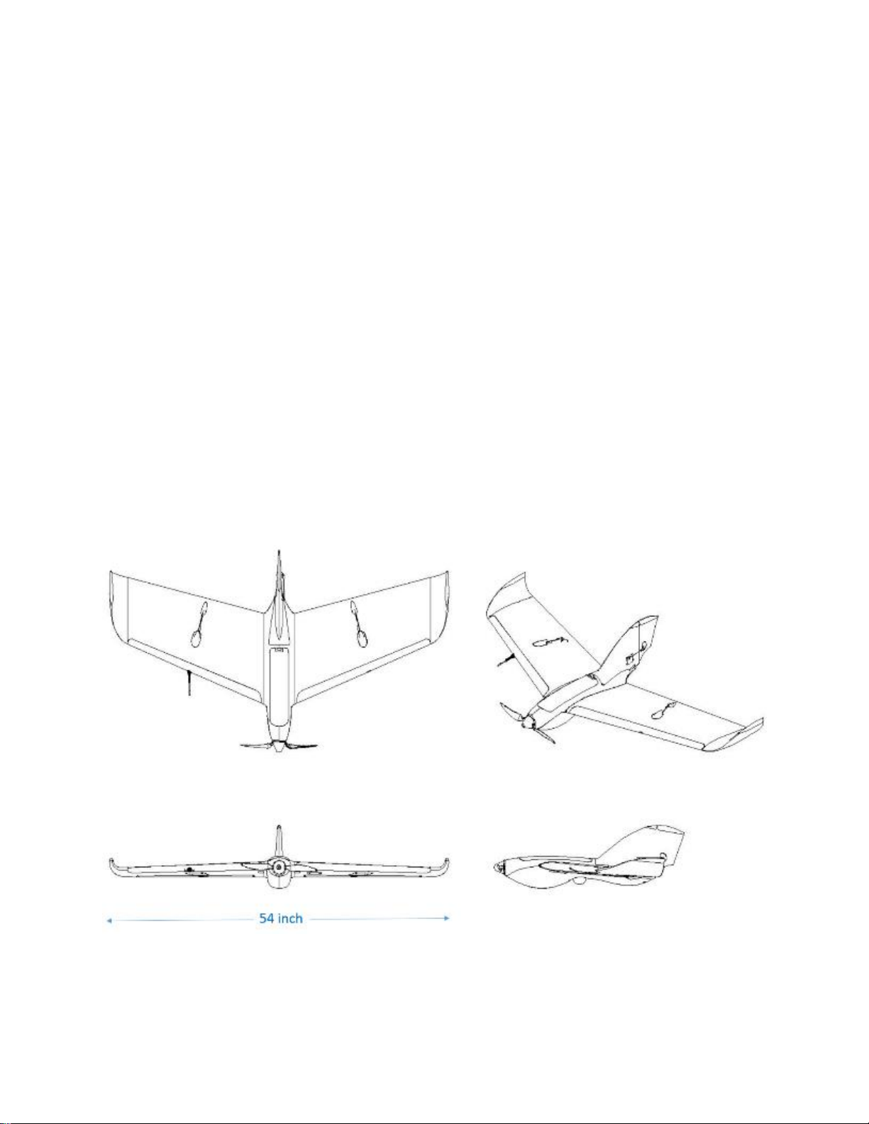
3-VIEW DRAWING
Page 7

1-2
Copyright Sentera LLC 2018
ACRONYMS, ABBREVIATIONS, SYMBOLS, AND
TERMINOLOGY
UAS TERMS:
UAS – unmanned aircraft system
GCS – ground control station
UA – unmanned aircraft
UAV – unmanned aerial vehicle
AIRCRAFT TERMS:
Pitot tube – Device that measures the speed of the air passing
by/over the air vehicle.
Control Surfaces (Elevons) – Flaps on the trailing edge of wings that
control aircraft orientation.
Fuselage – Primary enclosure that houses the autopilot, sensor, and
other essential electronics.
Payload/Sensor – Camera unit installed into the UAV to capture
mission imagery.
Servos – Geared electronic motors that operate control surfaces via
commands from the autopilot.
Magnetometers – Electronic sensors that measure the magnetic
orientation of aircraft (e.g. N,S,E,W).
C.G. – center of gravity
AVIATION TERMS:
Winds aloft – Speed and direction of winds at flight altitude.
Ground speed – Speed of the aircraft over the ground.
Airspeed – Speed of the relative wind over the aircraft and
conversely, the speed of the aircraft relative to the air mass.
GPS Altitude – Altitude of an aircraft determined by readings from the
GPS unit.
Page 8

1-3
Copyright Sentera LLC 2018
Barometric Altitude – (a.k.a. Baro Altitude) Altitude of aircraft
determined by readings from the barometric altimeter.
MSL – Altitude of an aircraft as measured above the average sea
level, calculated as a weighted average from the baro and GPS
measurements.
Pitch, Roll, and Yaw (Aircraft Attitude) – Pitch: nose up or down, Roll:
banking of wings, Yaw: left or right lateral motion of the aircraft nose.
USER INTERFACE TERMS:
Takeoff waypoint – Waypoint that aircraft will fly to after takeoff.
Land Waypoint – Waypoint that aircraft will touch down at when
landing.
Survey Waypoint Pattern – Waypoint pattern that outlines image
capture area and dictates where photos are taken.
Loiter Waypoint – Waypoint in which aircraft will circle indefinitely at a
predetermined altitude.
Artificial Horizon – Shows aircraft yaw, pitch, roll, and telemetry.
Failsafes – Time and altitude limits that an aircraft will adhere to in
case of lost link, lost GPS, and low battery.
Page 9

2-1
Copyright Sentera LLC 2018
SECTION 2: LIMITATIONS
The operator must ensure the system is operated within limits. The
autopilot and ground control station software have some built-in checks that
aid the operator, but ultimately the operator is responsible for keeping the
system within all limits.
SPEED LIMITS
The autopilot in the PHX UAS automatically maintains airspeed based on
the Pitot-static pressure measurements:
Vstall: 22 mph (19 kts, 10 m/s), standard sea level conditions
Vmin: 30 mph (26 kts, 13 m/s), autopilot limited
Vcruise: 35 mph (30 kts, 16 m/s), autopilot default
Vmax: 45 mph (40 kts, 20 m/s)
ALTITUDE LIMITS
The PHX UAS autopilot automatically maintains commanded altitude based
on the onboard barometric and GPS altitude sensors:
Minimum recommended cruise altitude: 150 ft. (46 m) AGL
Maximum density altitude: 14,000 ft. (4300 m) MSL (mean sea level)
Maximum altitude above ground: flight operations must remain
below the maximum altitude allowed by local regulations or local
airspace authority. Often this means below 400 ft. (120 m) AGL
(height above ground).
Page 10

2-2
Copyright Sentera LLC 2018
WIND LIMITS
Maximum winds aloft = 28 mph (24 kts, 12 m/s)
Maximum crosswind takeoff = 5 mph (4 kts, 2 m/s) crosswind
component
Maximum crosswind landing = 15 mph (13 kts, 7 m/s) crosswind
component
PRECIPITATION AND MOISTURE LIMITS
Do not fly in precipitation, fog, mist, or clouds.
GPS LIMITS
Minimum 10 GPS satellite fix recommended.
TEMPERATURE LIMITS
Operational temperature limits
Minimum = 14 F (-10 C)
Maximum = 120 F (50 C)
Storage temperature limits
Minimum = -10 F (-23 C)
Maximum = 120 F (50 C)
BATTERY LEVEL LIMITS
Maximum voltage: 12.6 volts
Nominal voltage: 11.1 volts
Minimum voltage: 9.0 volts
Warning: battery will be damaged if discharged below 9.0 volts during
operation or if left in storage for a long time. Check battery level every 3
months when storing and recharge to 50% storage level as needed.
Tip: Never go below 10% battery level during flight. Never go below 6%
battery level during ground handling.
Page 11
2-3
Copyright Sentera LLC 2018
TAKE-OFF AND LANDING AREA LIMITS
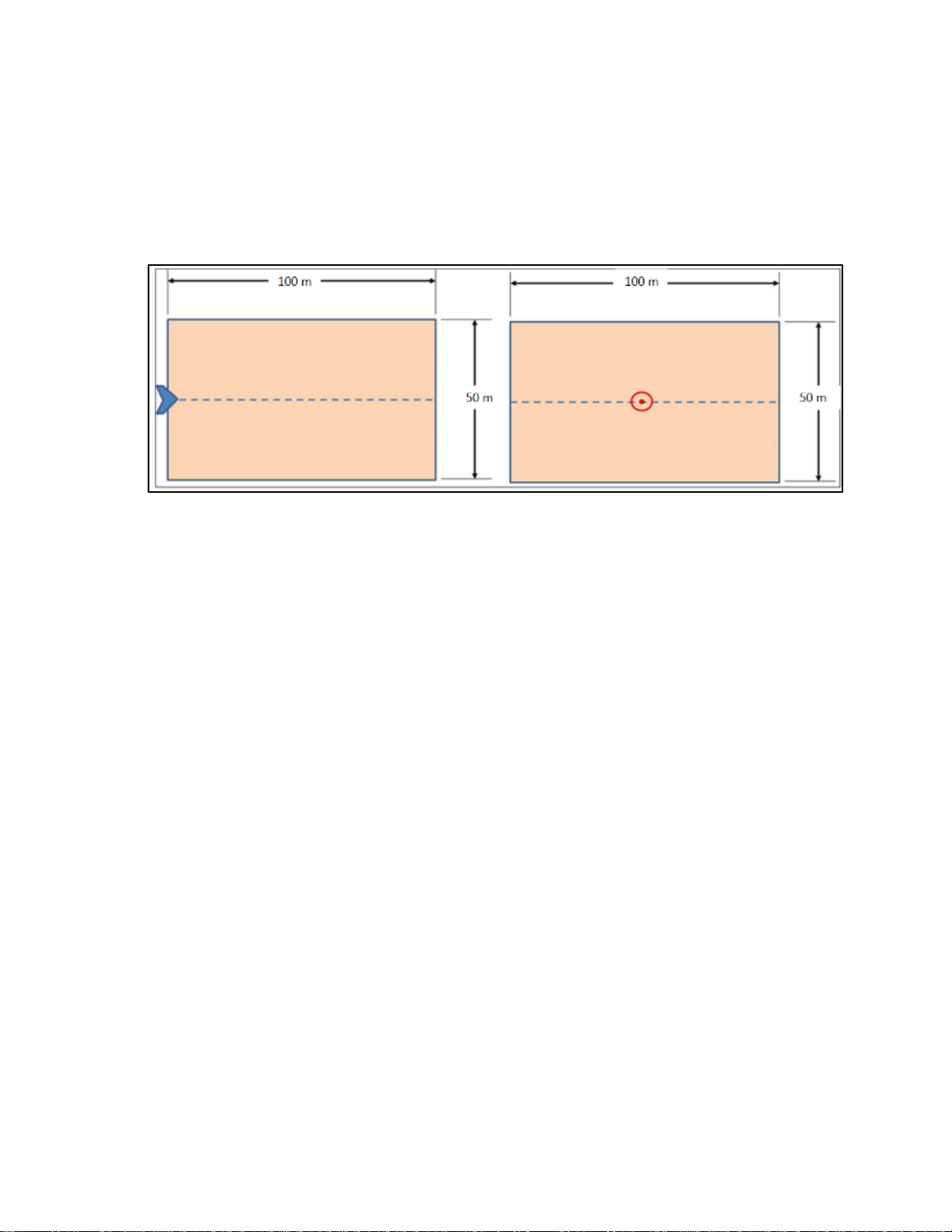
The launch and recovery area must be free of obstructions within an area
measuring 50 meters wide and 100 meters long, as shown below. This
area should also be kept free of persons during launch and landing, other
than the operator that is doing the launching.
Page 12

3-1
Copyright Sentera LLC 2018
SECTION 3: EMERGENCY PROCEDURES
The following are emergency procedures for the operator and autonomous
failsafe behaviors of the UAV.
LOSS OF PROPULSION
If propulsion power is lost the aircraft will automatically continue to fly the
pre-planned waypoints while gliding to the ground.
• Maintain visual contact with the aircraft.
• Avoid obstacles along the path using the normal waypoint and flight
mode commands to change the aircraft’s gliding direction (e.g. GoTo
location).
GCS SOFTWARE CRASH OR LOCK-UP
If the GCS software crashes or locks up:
• Force the software application to close.
• Re-launch the GCS software.
• Reconnect to the UAV in the normal way.
If the UAV does not receive communication from the GCS software within
the Lost Link time out period, the automatic Lost Link procedure will begin.
LOST LINK
If lost link occurs attempt troubleshoot and re-establish communications
with the aircraft:
• Maintain visual contact with the aircraft.
• Check antenna placement for RF line-of-sight.
• Check that the ground radio is powered
• Check cable or wireless connections between CommsBox and
computer.
Page 13

3-2
Copyright Sentera LLC 2018
Aircraft autonomous behavior during lost link
If communications are not re-established within the time out period
(typically 30 seconds) the aircraft will automatically Return to Land
(RTL).
If communications are regained, the operator may command the
aircraft back onto the flight plan or proceed to land the aircraft.
LOST GPS
If the aircraft loses GPS the operator should:
• Maintain visual contact with the aircraft.
Aircraft autonomous behavior during lost GPS:
If the aircraft loses GPS lock and it is not regained within a short
period the autopilot will cease flying the pre-programmed waypoints
and will begin slowly descending in a spiral circle pattern while it
waits to regain GPS lock or lands on the ground.
OTHER
For other emergencies the operator may:
• immediately press RTL to return to the landing location.
• put the aircraft in “Pause” or “Hold” mode and click “GoTo” locations
on the map to move the aircraft around.
• command the aircraft to glide to the ground at any time (if in
communications with the aircraft) by disarming the motor and
confirming “Emergency Stop” command.
MEDICAL
If there is a medical emergency with any involved personnel, flight
operations should cease and emergency responders should be contacted.
Page 14

3-3
Copyright Sentera LLC 2018
REPORTING
Incident reports should be logged and applicable authorities notified as
required.
Any incidents pertaining to the performance of the aircraft or other parts of
the system should be reported to the manufacturer. Telemetry logs files
from the Ground station, payload, and aircraft may be required to send to
the manufacturer.
Page 15
4-1
Copyright Sentera LLC 2018
SECTION 4: NORMAL PROCEDURES
FLIGHT PLANNING IN SENTERA GROUND CONTROL
SOFTWARE
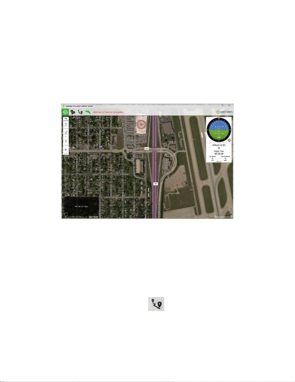
Sentera Ground Control is the software used to plan missions and control
the aircraft.
The data links should automatically connect once both the aircraft and GCS
are powered, the laptop is connected to the comms box (via cable or
wirelessly), and the software is running.
To create a flight plan in Sentera Ground Control:
1. Click on the Plan view icon.
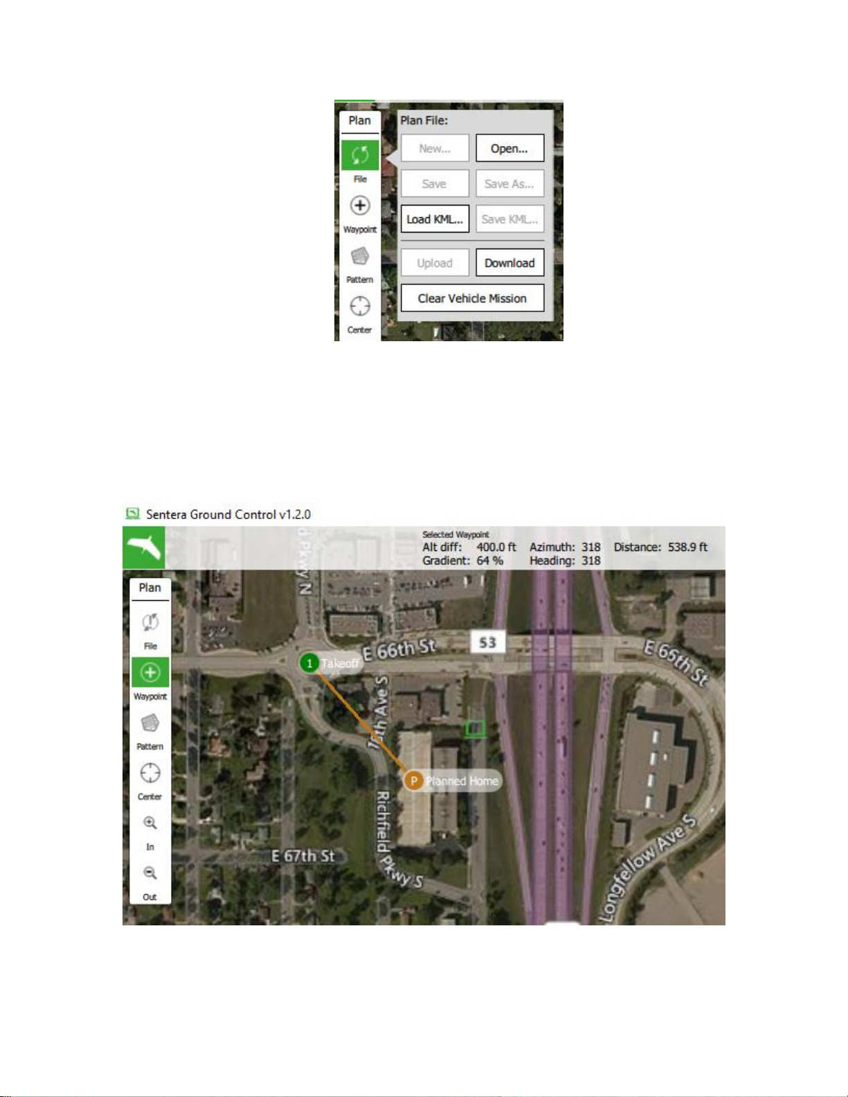
2. Remove the existing mission from the aircraft by pressing File and
the Clear Vehicle Mission buttons.
Page 16
4-2
Copyright Sentera LLC 2018
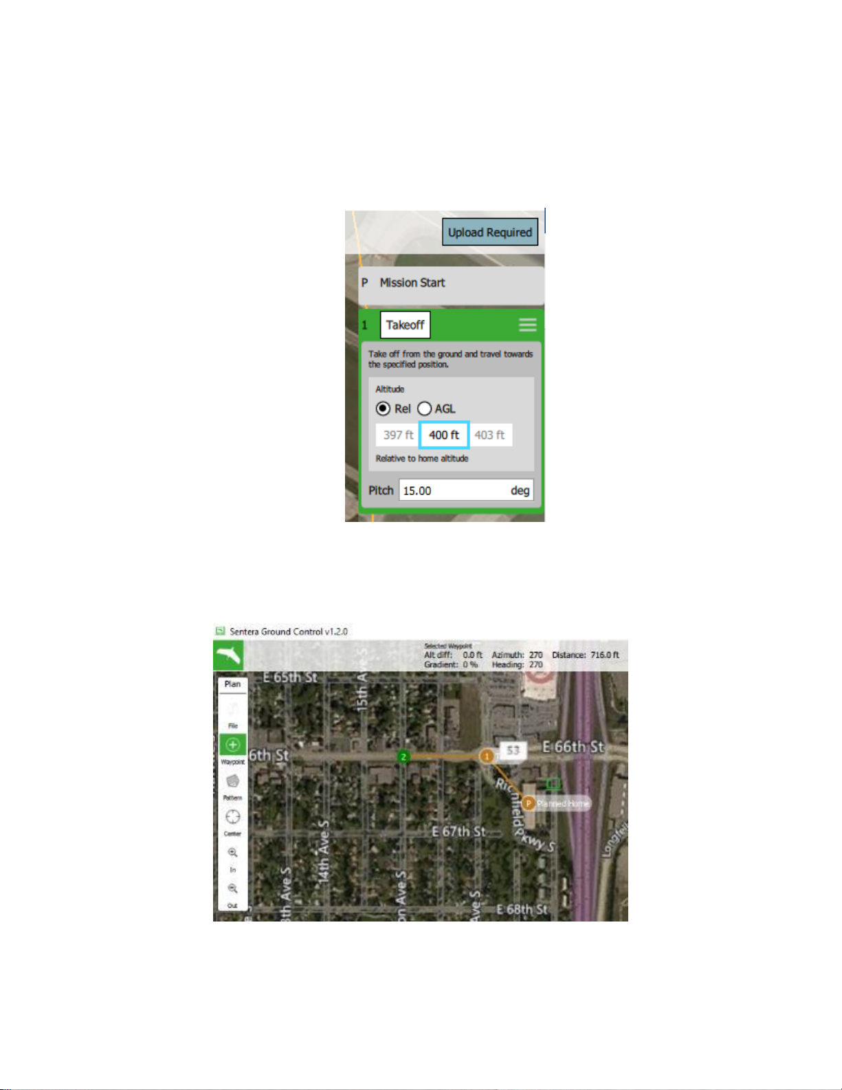
3. Create a Takeoff waypoint: Place the first waypoint by clicking on
the Waypoint icon and clicking a location on the map. By default the
first waypoint becomes your “Takeoff” waypoint which is where the
aircraft will fly to after launch.
Page 17
4-3
Copyright Sentera LLC 2018
4. Adjust the altitude of the Takeoff waypoint in the mission list on the
right hand side using the boxes to the right or left of the highlighted
box (Warning: do not adjust the Pitch value, leave at the default
which should be 15 degrees).
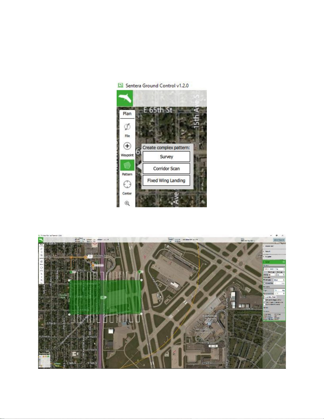
5. Place additional waypoints as needed.
Page 18
4-4
Copyright Sentera LLC 2018
6. Create a Survey Pattern: to map an area with the camera payload
click on Pattern and then Survey to create the default Survey pattern.
Adjust the settings in the Survey edit box on the right.
Page 19
4-5
Copyright Sentera LLC 2018
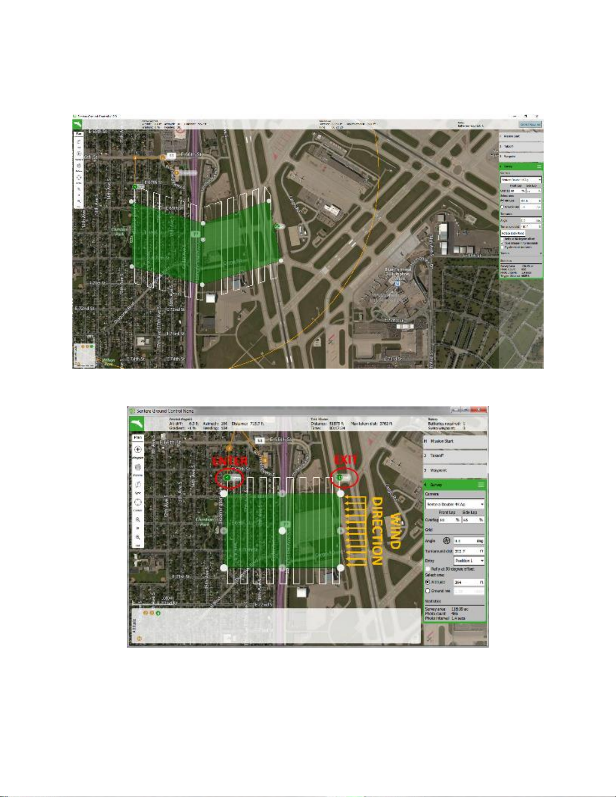
Click and drag corner dots, click the + dots, and drag the center dot to
adjust the size and shape of the survey.
Tip: If possible try to plan the survey perpendicular to the wind direction
with the aircraft starting downwind and working its way upwind. This
method may allow you to reduce the turnaround distance and optimize
flight performance.
Page 20
4-6
Copyright Sentera LLC 2018
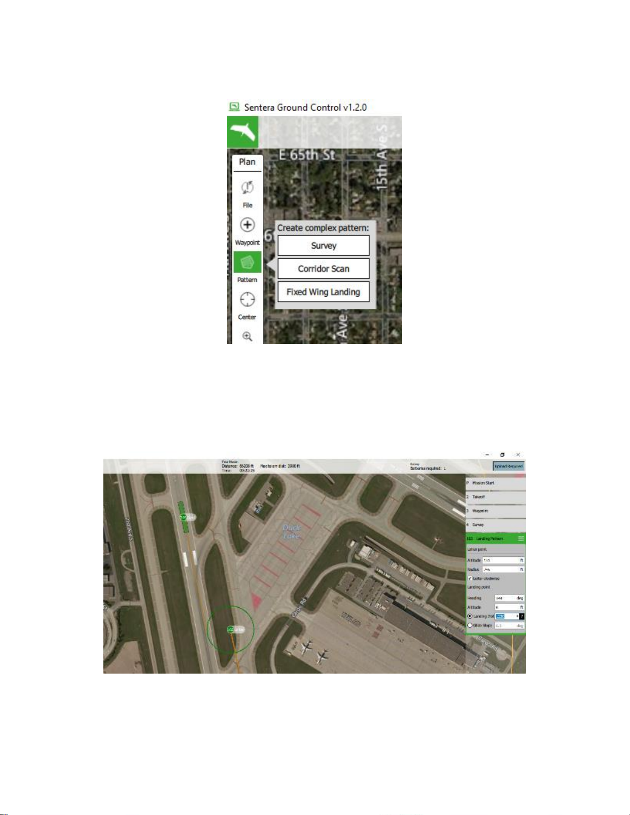
7. Plan a Landing Pattern: Click Pattern and then Fixed Wing Landing.
Click a location on the map for the landing point. Adjust the landing
direction by dragging the Loiter point. Adjust other landing values in the
Landing Pattern edit box on the right.
Tip: PHX recommended landing approach distance is 1300 ft. To
shorten this approach you will need to reduce the loiter altitude in the
Landing Pattern edit box.
Page 21
4-7
Copyright Sentera LLC 2018
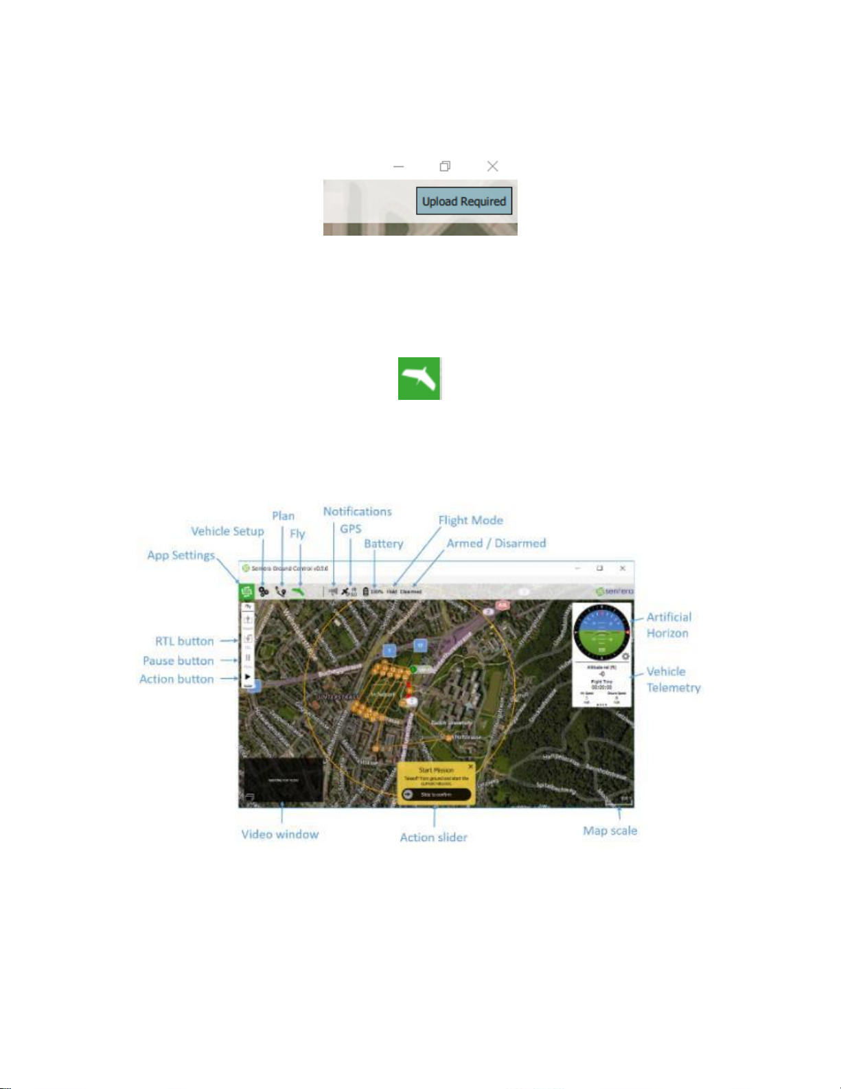
8. Upload Your Mission: Press the upload mission button in the upper
right-hand corner and ensure the mission uploads with no errors.
PRE-FLIGHT ACTIVITIES
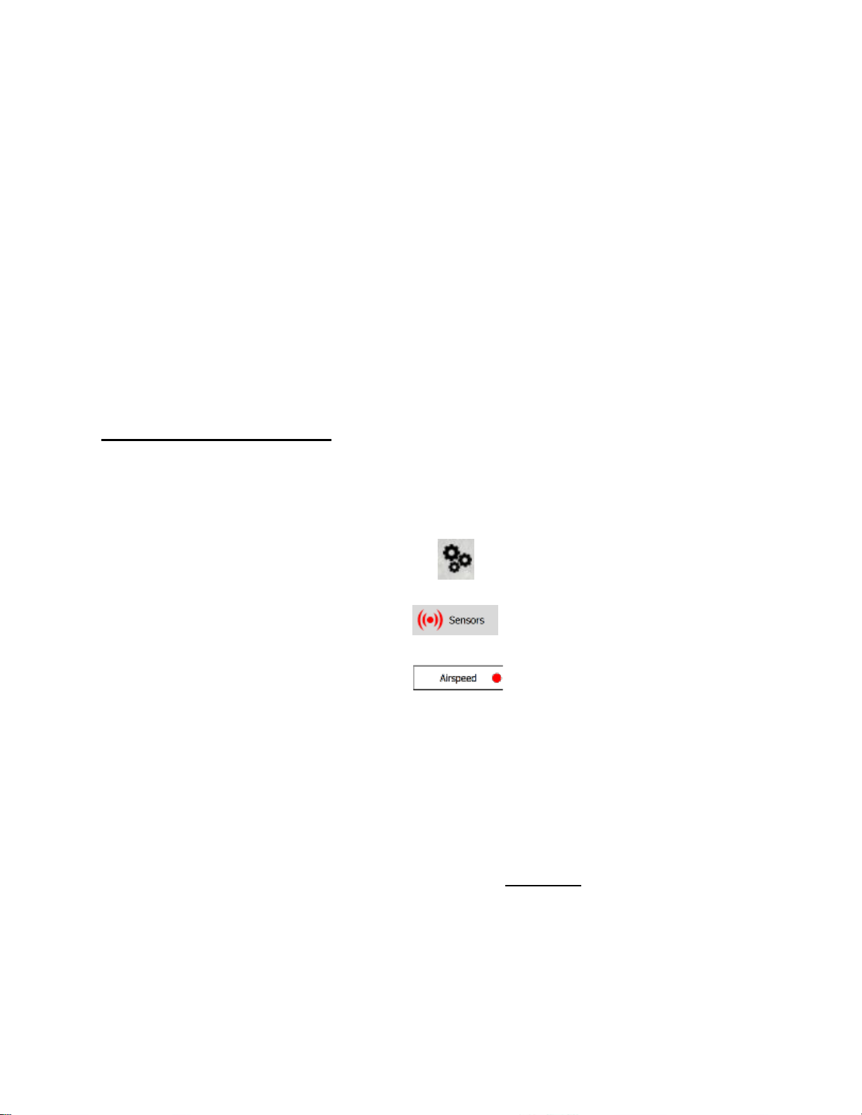
Switch to the Fly view screen for pre-flight by clicking on the airplane button
at the top of the screen.
If connected to an aircraft, you will see all the important status information
at the top of the screen and in the right-hand artificial horizon and telemetry
indicators.
If all systems show correct you are ready to begin pre-flight activities which
may involve compass and/or airspeed calibration and will involve the preflight checklist.
Page 22
4-8
Copyright Sentera LLC 2018
AIRSPEED CALIBRATION
The airspeed sensor is sensitive to air temperature. Verify it reads
between +/- 5 mph while blocking the pitot tube from wind. If it reads
outside of +/- 5 mph, re-calibrate.
The airspeed measurement is sensitive to leaks in the tubing. Check that
the tubing holds pressure by pressing your finger over the end of the pitot
tube and verify airspeed reads positive > 20 mph (> 10 m/s) and holds >20
mph for 3 seconds. If airspeed is negative or does not hold > 20 mph for 3
seconds, repair or replace the pitot or tubing.
Only recalibrate if needed!
To re-calibrate the airspeed sensor do the following while connected to the
aircraft in Sentera Ground Control:
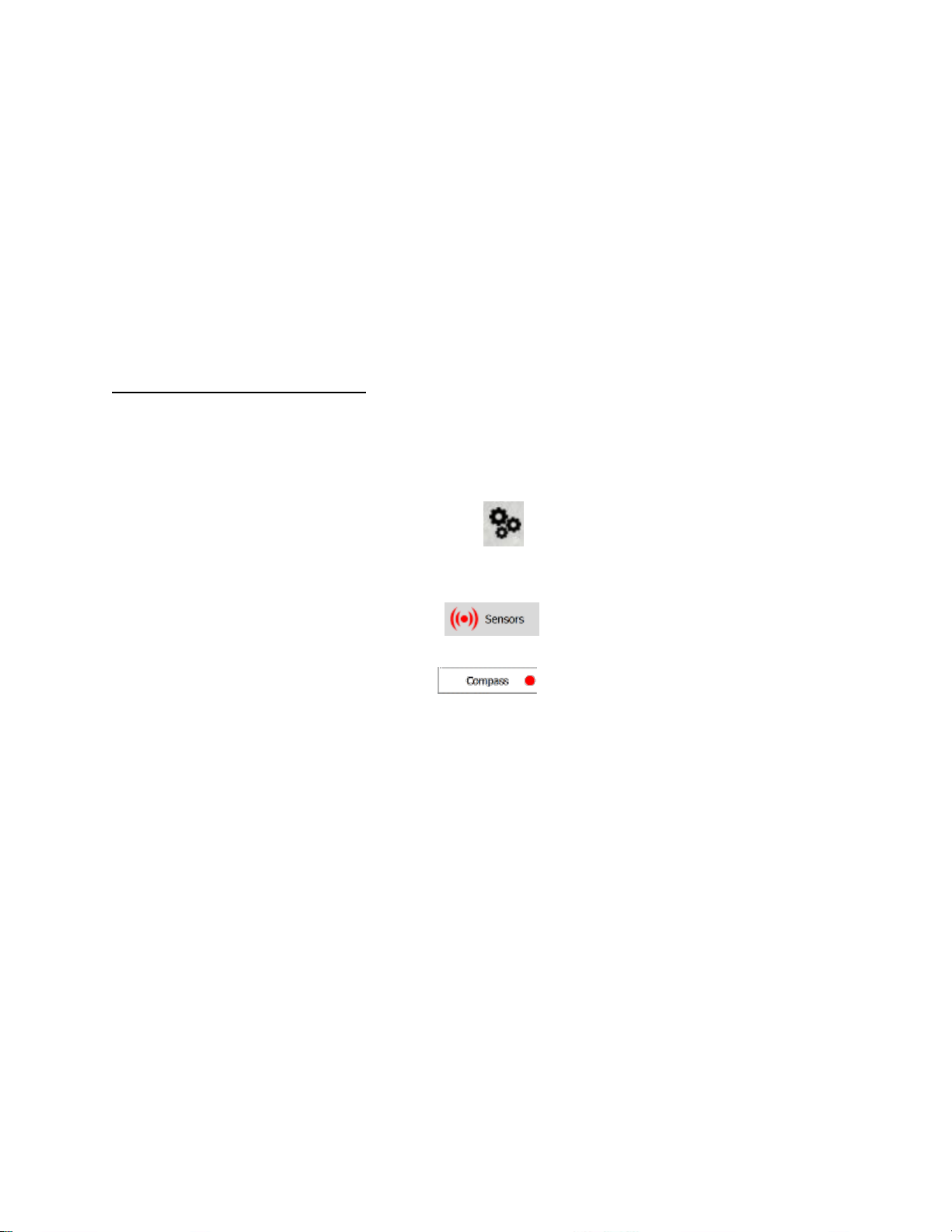
1. Click the Gears button at the top of the screen.
2. Click on Sensors
3. Click on Airspeed
4. Follow the onscreen instructions about blocking the pitot-static tube
from all wind without touching the holes.
5. Press the “OKAY” button in the upper right to start.
6. The on-screen directions will eventually instruct the you to blow
across the pitot tube to create pressure. DO NOT blow into the pitot
tube. Instead press the pad of your finger against the end of the tube
to create pressure.
Page 23
4-9
Copyright Sentera LLC 2018
MAGNETIC COMPASS CALIBRATION
If during the pre-flight checks the magnetic compass is off by more than 510 degrees in any of the north (0/360), east (90), south (180), west (270)
directions you should perform a compass calibration. Stand at least 30 ft
(10 m) away from any metal when checking and re-calibrate only if any
direction reads greater than 5-10 degrees from truth.
Only recalibrate if needed!
To re-calibrate the magnetic compass do the following while connected to
the aircraft in Sentera Ground Control:
1. Click the Gears button at the top of the screen.
2. Click on Sensors
3. Click on Compass
4. Press the “OKAY” button in the upper right and follow the onscreen
steps.
5. After the calibration process is complete the autopilot will
automatically self-reboot. A series of beeps will indicate this process.
6. After the autopilot self-reboots power cycle the aircraft by removing
the battery then re-inserting it.
7. After rebooting and reconnecting to aircraft, verify north, east, south,
west directions.
Page 24

4-10
Copyright Sentera LLC 2018
CHECKLISTS
To avoid missing important steps, always use the appropriate checklists.
Consistent adherence to approved checklists is a sign of a disciplined and
competent pilot.
Included in this handbook are:
• Pre-Flight Checklist
• During flight status scan
• Landing Procedure
NOTE: Proper following and proper technique of ALL steps on the PreFlight checklist is CRITICAL to flight safety and avoiding potential damage
to your aircraft and payload.
Additional checklists and procedures for different payloads should be
followed as appropriate.
Page 25
4-11
Copyright Sentera LLC 2018
EXAMPLE PRE-FLIGHT CHECKLIST
Revision Date: 13 July 2018
Page 26

4-12
Copyright Sentera LLC 2018
DURING FLIGHT AIRCRAFT STATUS SCAN
__Maintain visual contact with aircraft
__Check aircraft location and heading on the map
__Check all status indicators at the top of the screen
__Check altitude and airspeed
__Check message window
__Check status of payload
__Maintain visual contact with aircraft
LANDING PROCEDURE
__Maintain visual contact with aircraft
__Check landing area is clear
__Check wind direction and speed
__ (If needed, adjust landing approach and re-upload)
__Press [RTL] button if not already heading to landing pattern
__Verify aircraft enters final approach by seeing the Abort! slider
appear
__ (if needed, abort the landing by sliding the Abort slider)
__After landing, disarm the motor
__Verify no damage to aircraft
__Remove battery from aircraft
LAUNCH TECHNIQUE
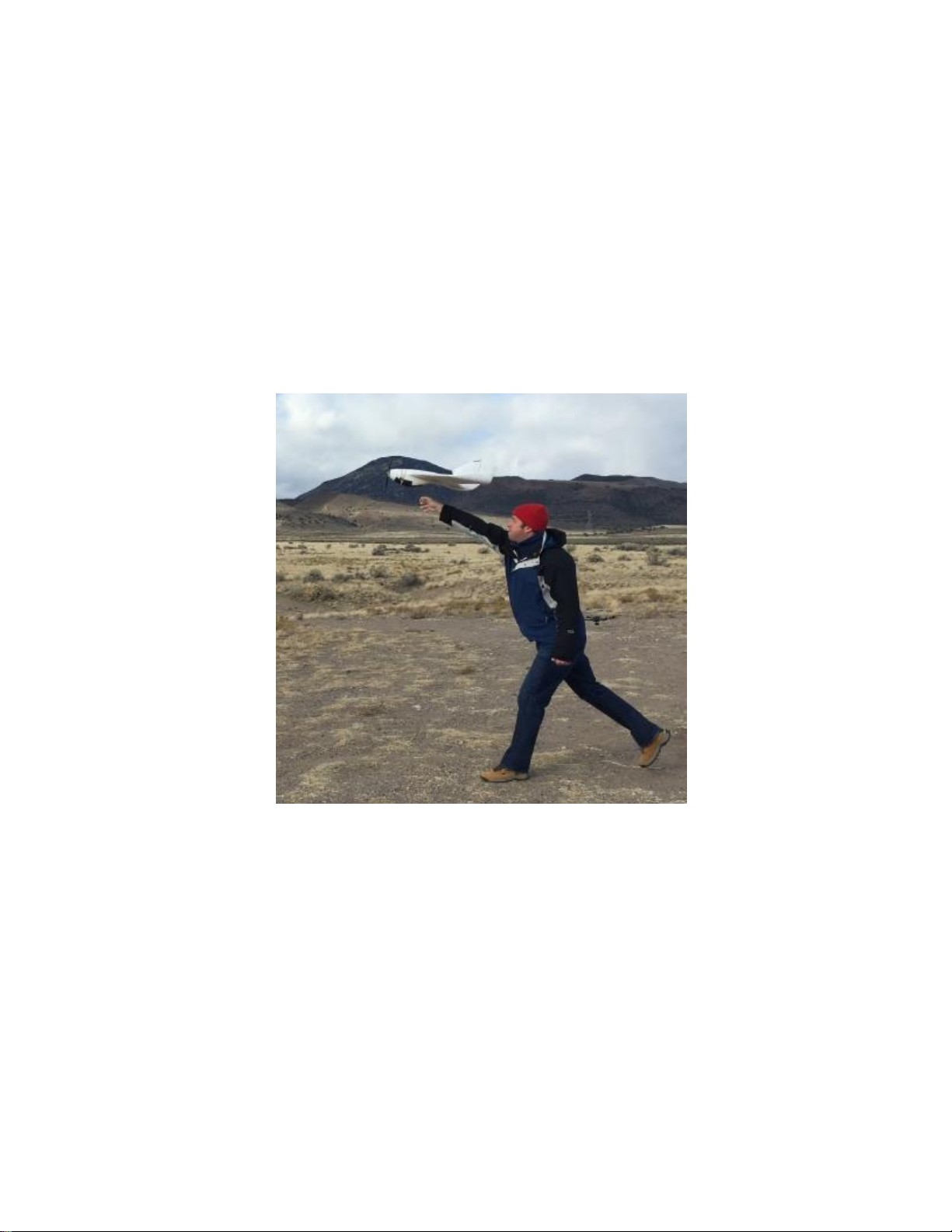
Always launch into the wind. Only a slight cross wind component is
allowed. Hold the aircraft wings level above your head. Point the nose
straight toward or just above the horizon. Shake the aircraft forward once
to start the motor. Take 1 step forward to gain momentum and then firmly
push the aircraft straight forward without stopping. Push harder than the
propeller is pulling. If the aircraft does not detect flight after 2 seconds the
Page 27
4-13
Copyright Sentera LLC 2018
motor will stop so push the aircraft to launch it immediately after motor
start. In zero wind a more vigorous push or jog will be necessary to gain
enough airspeed. Always launch with a >95% full battery for maximum
launch thrust.
PROPELLER WARNING:
Be sure to keep hands and other body parts away from the propeller
at all times. Do not pull the propeller back near your face or any other
part of your body.
PHX HAND LAUNCH SUMMARY:
• Shake once to start motor
• Step forward and push immediately after motor start
• Push harder than the propeller is pulling
• Always into the wind
• Wings level with the horizon
• Nose slightly up
Page 28

4-14
Copyright Sentera LLC 2018
LANDING TECHNIQUE
Prior to landing check the wind direction and make adjustments as
necessary to the flight plan. Upload any changes to the flight plan prior to
landing.
Use the Abort! slider if a go-around is necessary. The aircraft will abort to a
loiter above the landing waypoint. To re-start the landing switch back to
Mission mode or press RTL.
Tip: landing on soft surfaces such as grass will prolong the life of your PHX
UAV. When landing on hard surfaces such as asphalt or gravel use a few
pieces of tape on the bottom contact points and well as the underside of
the wing tips to protect the aircraft from excessive scratching.
ADVANCED PLANNING FOR LANDING PATTERNS
Occasionally the default landing pattern will not work for certain flying
locations. This may be due to trees, power lines, wind conditions, or other
reasons. In these cases it may be possible to manually plan a box pattern
style landing that will avoid obstructions.
(1) Place a normal waypoint somewhere on the map near the end
of your planned mission. Change it to a “Land Start” waypoint
by editing it in the right hand waypoint list.
(2) Begin placing waypoints in the shape of your desired custom
landing pattern. A traditional cross-wind, down-wind, base leg,
and final approach pattern works well in many situations.
(3) Finally place a waypoint at your desired landing location and
change it to a “Land” waypoint. Verify altitude = 0 for your Land
waypoint.
(4) Adjust the altitude of each of your waypoints between the “Land
Start” and the “Land” waypoints to step down the flight path.
You must be careful not to place waypoints too close or have
too large of a drop in altitude, otherwise the aircraft may take
unexpected turns to try to achieve the tight waypoints which is
undesirable.
Page 29

5-15
Copyright Sentera LLC 2018
SECTION 5: PERFORMANCE
PERFORMANCE CHARACTERISTICS
Cruise speed
35 mph
Stall speed
23 mph
Max speed
45 mph
Climb rate
800 ft./min
Decent rate
400 ft./min
Turn rate
10 deg./sec
Turn radius
200 ft.
Typical operating altitude
< 400 ft. AGL
Maximum operating altitude
12000 ft. MSL
Max endurance (depending on payload)
up to 60 min
Max control range (RF line-of-sight)
1 miles
Typical visual line-of-sight range
(dependent on weather conditions)
Up to 1 mile
Motor RPM (MAX)
7000 (typical)
Motor Power (MAX)
600 (watts)
Maximum load factor
10 G’s
Bank angle (autopilot limited)
37 (degrees)
Pitch angle (autopilot limited)
50 (degrees)
Best Glide Ratio
10 to 1
Page 30
6-1
Copyright Sentera LLC 2018
SECTION 6: WEIGHT AND BALANCE
WEIGHT
PHX is battery powered. Its weight does not change during flight.
Weight (pounds)
Maximum Weight
5.6
Nominal Weight
4.4
CENTER OF GRAVITY
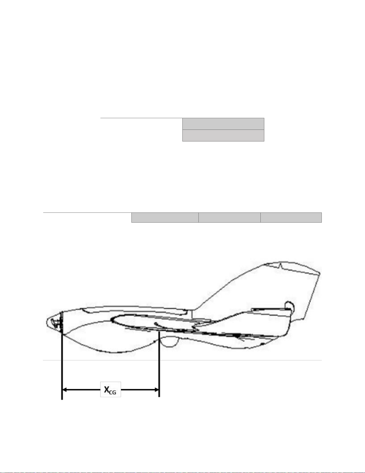
PHX is battery powered therefor C.G. does not change during the course of
the flight. C.G. is measured from the front point of the fuselage where the
motor mount attaches.
Forward Limit
Nominal
Aft Limit
Center of Gravity (in)
10.5
10.7
10.8
Page 31
7-1
Copyright Sentera LLC 2018
SECTION 7: SYSTEM DESCRIPTION
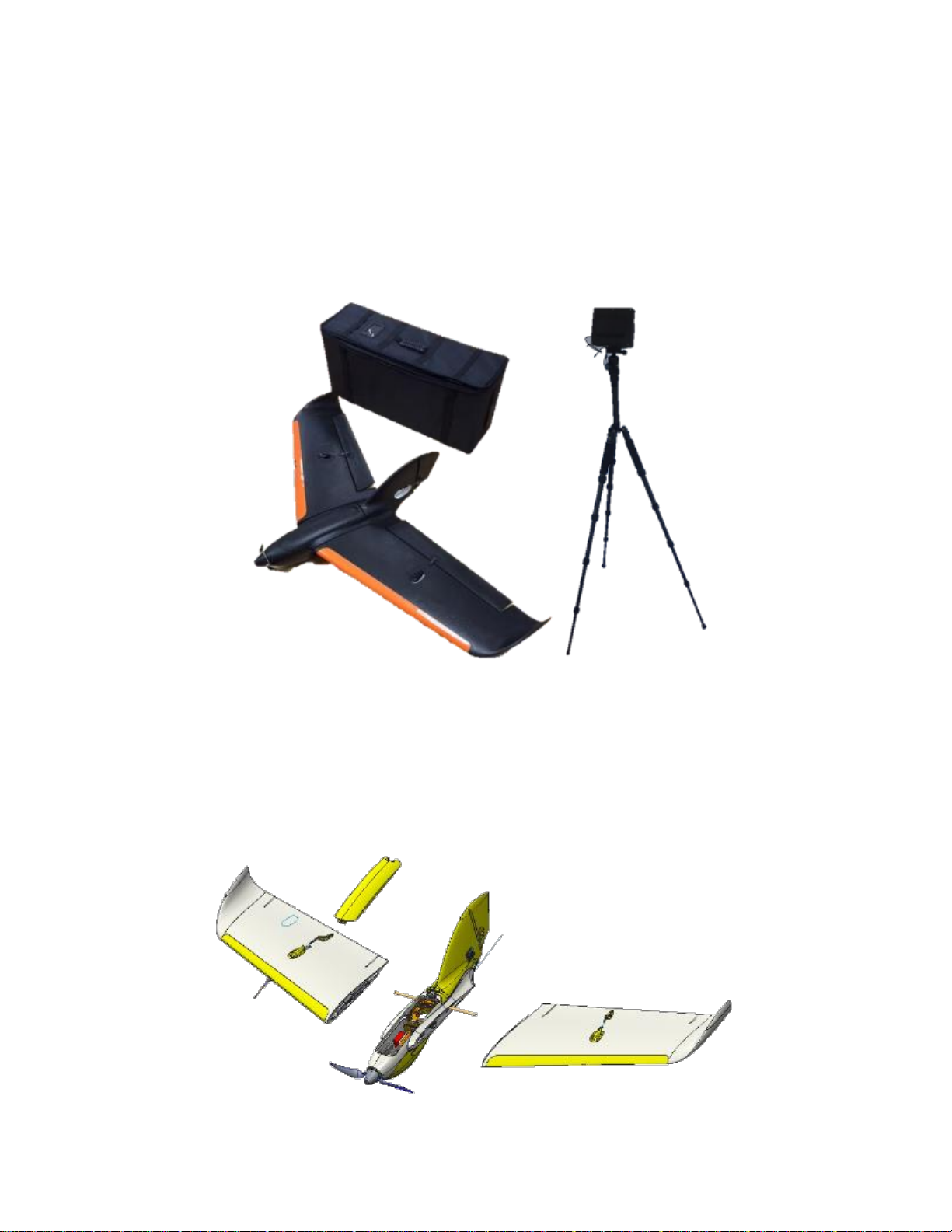
The PHX UAS is comprised of an unmanned aircraft, a ground control
station, a data-link communications system, and maintenance and support
equipment. The aircraft typically carries a camera payload.
AIRCRAFT DESCRIPTION
The PHX unmanned aircraft is a hand-launched electric aircraft constructed
of rugged materials. The wings and battery assemble to the fuselage
without requiring the use of tools.
Page 32
7-2
Copyright Sentera LLC 2018
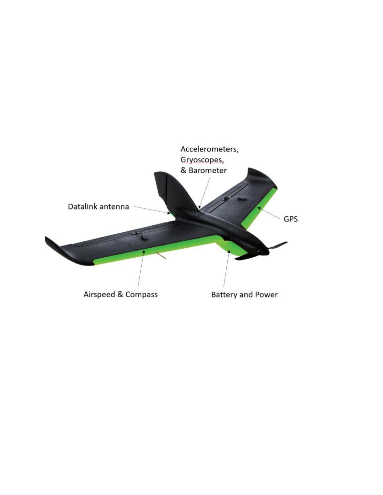
AIRCRAFT SENSORS
The aircraft has many sensors onboard that help it fly. Proper sensor
operation is critical to safe flight. The datalink antenna is near the back of
the tail. The accelerometers, gyroscopes, and barometer are located under
the tail. The GPS is in the left wing. Power sensors are in the battery bay.
The airspeed sensor and compass are located in the right wing.
LIST OF EQUIPMENT
• CommsBox (Flight critical)
• Tripod
• Battery x2 (Flight critical)
• FSK
• Ethernet cable
• Payload
• CommsBox charger
• PHX charger
• USB thumb drive
Page 33
7-3
Copyright Sentera LLC 2018
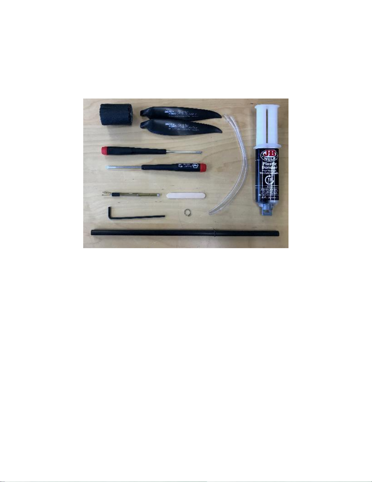
FIELD SUPPORT KIT DESCRIPTION
The PHX comes with a field support kit that contains a few basic hand tools
and spare parts for common wear items that require regular maintenance
(e.g. propellers, wing spar, and pitot-static tube).
Page 34
8-1
Copyright Sentera LLC 2018
SECTION 8: HANDLING, SERVICE, AND
MAINTENANCE
BATTERY CHARGING
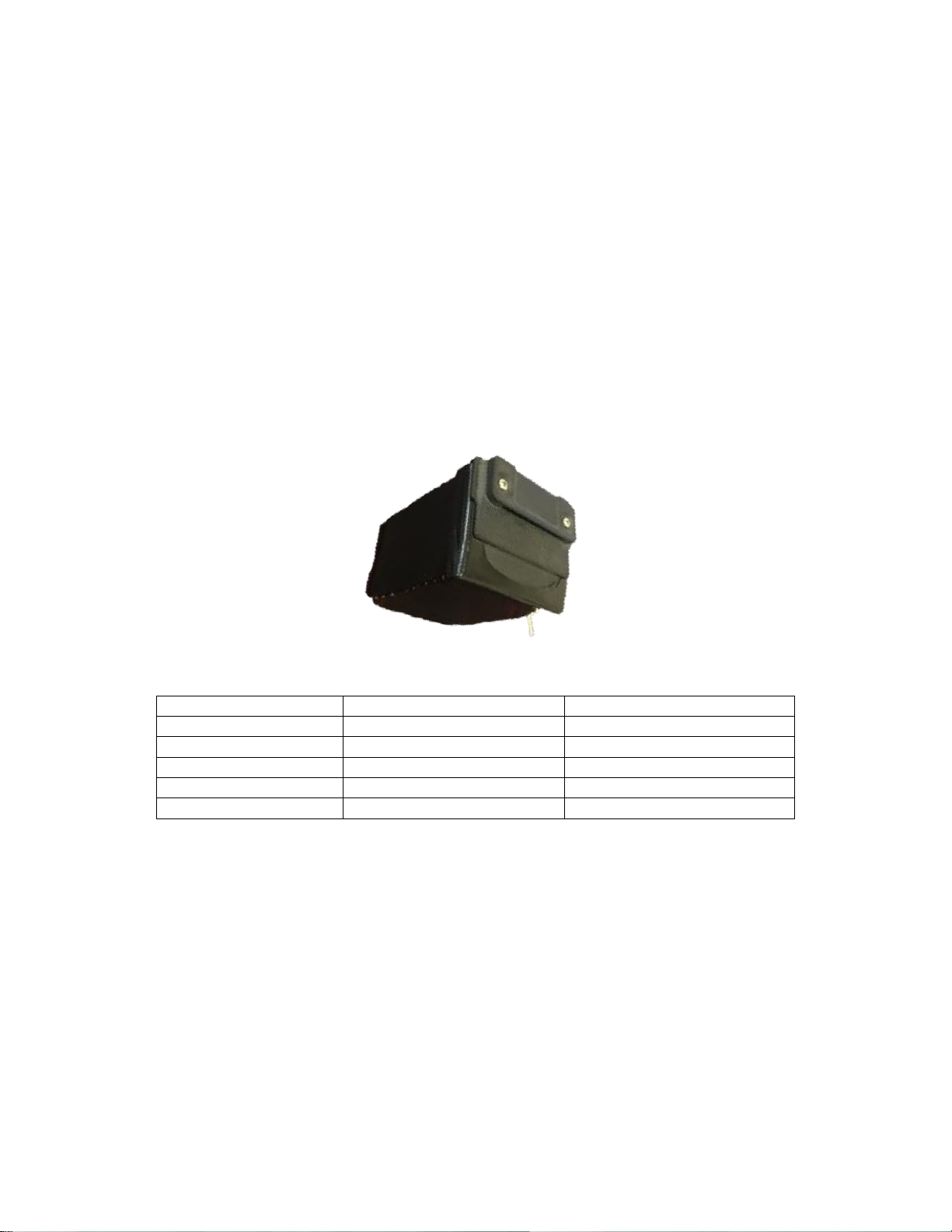
The PHX aircraft is powered by a lithium polymer battery with a built-in
smart battery fuel gauge.
The battery level indicator lights can be displayed at any time by pressing
the button on the battery.
Air Vehicle Battery Indicators (when pressed or charging)
Indicator State
Status
Battery State of Charge
1 LED On
Constant current charging
0-25 % charged
2 LEDs On
Constant current charging
25-50 % charged
3 LEDs On
Constant current charging
50-75 % charged
4 LEDs On
Constant voltage charging
75-97 % charged
5 LEDs On
Battery charged
> 97 % Charged
The PHX smart battery automatically maintains balance between the cells
without the need for an external balancing charger.
The battery charger supplied with the system ensures safe charging of the
PHX batteries and is the only charger that should be used.
Page 35
8-2
Copyright Sentera LLC 2018
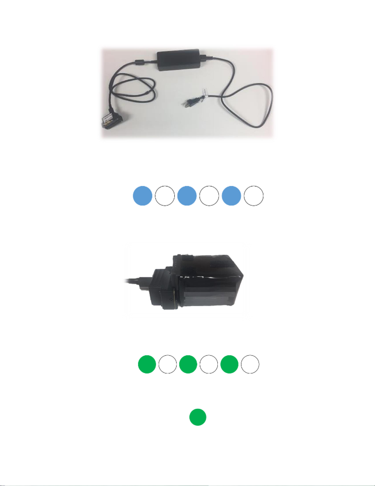
To charge a battery:
1. Plug the charger into AC wall power. Verify Blue - White alternating
blink on the charger indicating it is ready.
2. Connect a battery to the charge paddle. Charging should start
automatically.
3. Verify the charge cycle starts indicated by a beep sound and Green White alternating blink.
4. The charger will beep when complete. The charger LED will show
solid Green.
Page 36
8-3
Copyright Sentera LLC 2018
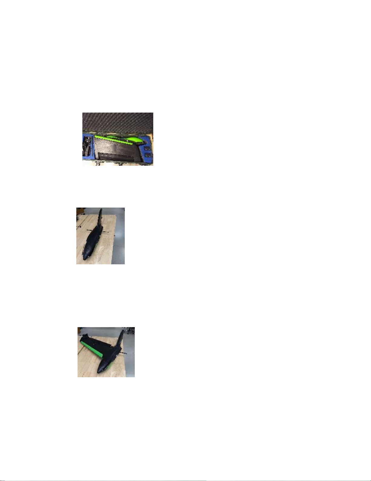
The battery level indicator lights on the battery light up while charging to
provide an indication of charge level.
ASSEMBLY: AIR VEHICLE
1. Open transport case.
2. Remove left wing, fuselage, and right wing, inspect for damage.
3. Insert wing spar into the fuselage, verify it protrudes evenly from
both sides of the fuselage.
4. Grip the wing by the leading edge close to the wing tip and slide
the wings onto the spar and press into the fuselage’s wing pockets
verify they snap in place and are secure.
5. Verify the Pitot-static tube is straight and secure.
6. When ready to begin preflight, insert a fully charged battery into
the fuselage under the top hatch.
7. Verify top hatch is secure.
Page 37
8-4
Copyright Sentera LLC 2018
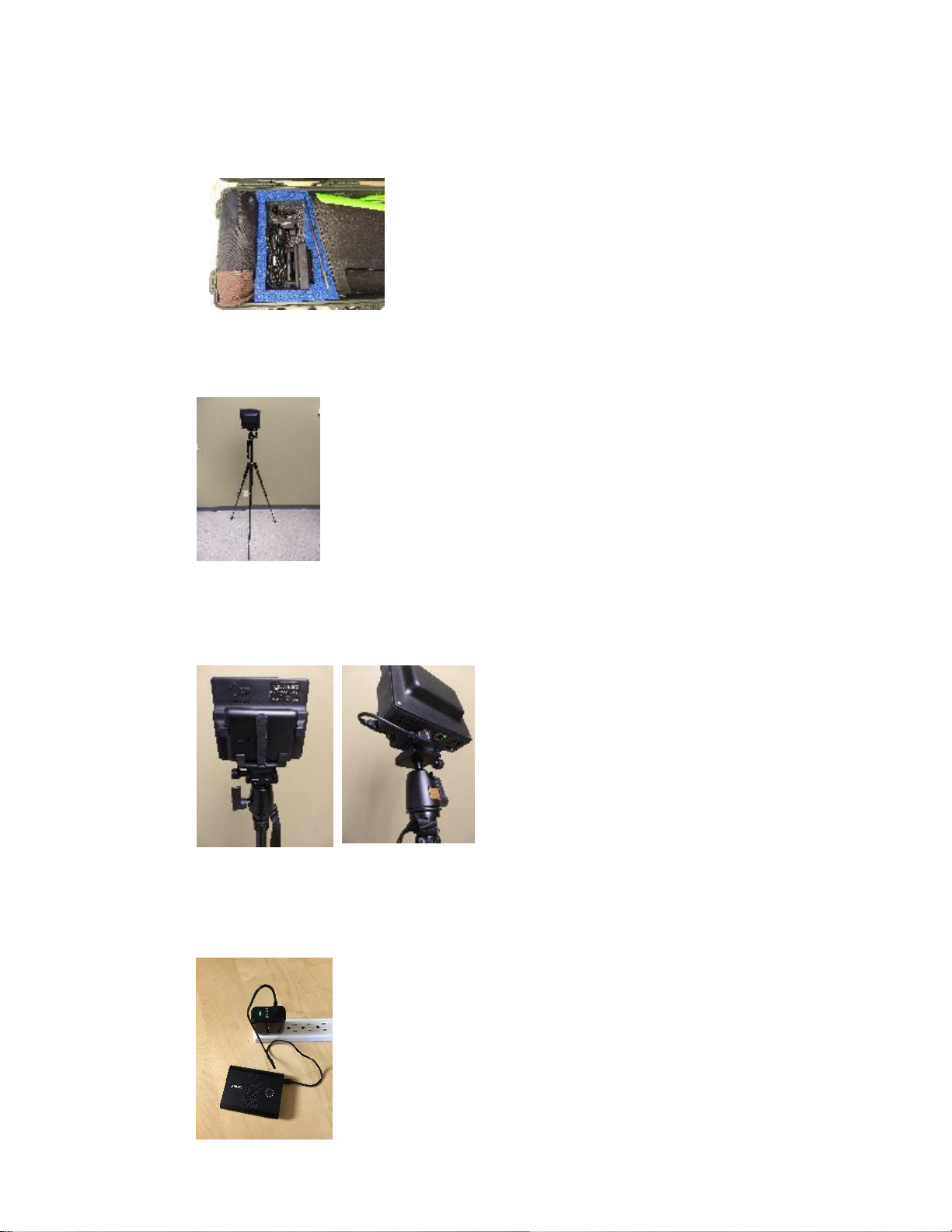
ASSEMBLY: COMMS BOX
1. Open transport case.
2. Remove tripod and extend legs.
3. Attach the Comms Box to the tripod
4. Connect the battery to the Comms box using the provided cable.
5. Verify that the fan is on.
6. Charging: remove the AC adapter from the transport case and
plug into an outlet as shown
Page 38
8-5
Copyright Sentera LLC 2018
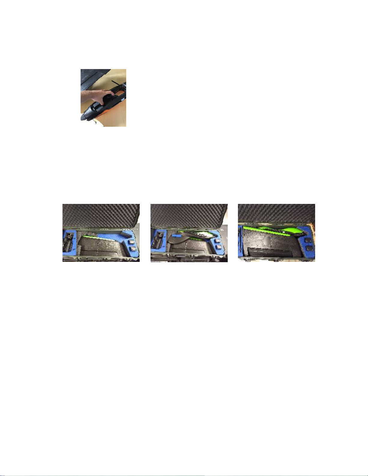
DISASSEMBLY AND PACKING: AIR VEHICLE
1. Remove battery
2. Grip the wing in the same location as assembly and pull away from
the fuselage
3. Remove wing spar
4. Verify the components are placed correctly into the transport case.
STORAGE
The system should be stored in a dry location within the storage
temperature limits listed in Section 2 of this handbook.
Battery Maintenance and Storage:
If not used for long periods of time, air vehicle batteries should be
stored at 40-60% charge capacity. Batteries should be periodically
checked for remaining capacity every three months. If necessary,
batteries in storage should be charged back to the 40-60% charge
capacity.
Battery Disposal:
At the end of their usable life the AV and GCS batteries should be
disposed of properly in accordance with local regulations.
Page 39

8-6
Copyright Sentera LLC 2018
TRANSPORTATION
The system should be transported in its packed away configuration. Use
soft packing material inside the case to ensure components to not move
during shipping.
Battery transportation:
Lithium batteries must be shipped in accordance with local
regulations. The PHX batteries are lithium polymer and typically must
be shipped via a ground carrier.
SERVICE AND MAINTENANCE
Most simple repairs of “wear” items or minor damage can be done in the
field using tools and spare items included in the FSK.
PROPELLER REPLACEMENT
Inspect both propellers for damage including chips, broken tips, or
other damage prior to flight. In the case of a damaged propeller,
unscrew the broken or damaged propeller by loosening the #1
Phillips screw. Install a new propeller and replace the screw. Tighten
the screw so that there is light friction on the folding propeller.
PITOT-STATIC TUBE REPLACEMENT
The pitot-static tube may need to be replaced if damaged or if the
aircraft is not properly sensing airspeed. For a video tutorial visit our
support site: https://sentera.freshdesk.com/support/home
Remove the pitot-static tube by:
1) Press the pitot backwards into the spring (the clear plastic
sleeve provides friction) until it is free and loose inside the
spring.
2) Unscrew or slide the spring from the foam wing until it is out of
the wing. Avoid twisting the pitot-static tube and hoses.
Page 40

8-7
Copyright Sentera LLC 2018
3) Slide clear pneumatic tubing off the rear barbs and re-install the
clear tubing onto the same rear barbs on the new pitot-static
tube.
4) Screw or slide the spring back into the foam wing with the pitotstatic tube loose inside the spring. Avoid twisting the pitot-static
tube and hoses.
5) Pull the pitot-static tube back out straight into the spring.
Ensure the clear plastic tube is fully engaged by friction with the
spring.
6) You may need to remove the servo cover on the bottom of the
wing to pull extra slack in the air hoses and ensure there is no
kinks. Replace the cover when done.
MINOR STRUCTURAL REPAIR
Minor structural damage can be repaired using JB Weld Plastic Bonder or “gaffer’s”
tape. Be sure not to add too much weight or unbalance the aircraft when repairing. For
a video tutorial visit our support site: https://sentera.freshdesk.com/support/home
Item
Description
Repair Method
Foam
Cosmetic non-structural
blemish
Use RTV silicone to fill in the damage
Damage between a
plastic and a foam
component
Use JB weld plastic bonder to repair
Cracked foam
Use UHU POR EPP glue or JB weld plastic bonder to
repair
Fully separated foam
Use JB weld plastic bonder to repair
Non-flight critical
missing section
Use a piece(s) of gaffer tape to cover the missing section
Use RTV silicone or JB weld plastic bonder to fill in the
missing section
Polycarbonate
Dented or heavily
damaged
Remove the damaged polycarbonate from the foam.
Repair any structural foam damage. Use UHU POR EPP
glue to bond the new polycarbonate piece to foam
Plastic
components
Broken or cracked
Remove and replace with new components if available
Remove broken component and use JB weld plastic
bonder to repair.
Spar Joiner
Retaining ring
separation
Use JB weld plastic bonder to repair
Broken carbon
Replace the spar joiner
Page 41

8-8
Copyright Sentera LLC 2018
SPINNER REPLACEMENT
If the spinner becomes damaged, unscrew and remove the spinner
cone. While holding the propeller stationary, use the hex driver to
loosen the screw holding the collet and yoke onto the motor shaft.
Replace spinner assembly and tighten screw tight as possible using
hex driver in the FSK. Ensure the collet is all the way pressed onto
the shaft and that the motor/propeller spins freely with no rubbing.
AIR SPEED SENSOR REPLACEMENT
If the air speed sensor (air data module) needs replacement, remove
the cover from the servo bay, carefully remove the air speed sensor
using the #1 Philips screwdriver with tubes and wires attached.
Remove the electrical cable and the pneumatic tubes. Trim the used
ends of the pneumatic tubing off. Plug the electrical cable and
pneumatic tubes into the replacement air speed sensor into the same
ports. Re-install the assembly into the wing. Ensure the pneumatic
tubes are not pinched. Re-calibrate BOTH airspeed and magnetic
compass as described in this document.
MOTOR REPLACEMENT
The motor should be replaced if any damage is suspected or when it
starts to make louder than usual noises (sign of the bearings wearing
out). A well cared for motor will last well over 100 hours of operation.
Remove the motor assembly by first removing the spinner cone
screw and spinner cone. Next, remove the motor assembly from the
fuselage by removing 4 screws. Before the motor can be pulled out of
the fuselage, the 3 phase wires must be un-screwed from the clamp
underneath the foam block inside the battery bay. Then, unplug the
motor’s 3 bullet connectors from the propulsion wire harness.
Plug the new motor’s three bullet connectors into the propulsion wire
harness. Match the colors used on the old motor. Install the motor
screws and mount plate. Re-install the spinner and propeller. If the
new motor spins backwards then swap any 2 of the bullet connectors.
Page 42

8-9
Copyright Sentera LLC 2018
PROPULSION WIRE HARNESS REPLACEMENT
The propulsion assembly may need to be replaced if it becomes
damaged or if the air vehicle motor will not function properly.
Remove the propulsion wire harness by removing carefully prying it
off the Velcro fasteners, unplug the various cables, and replace.
Page 43

8-10
Copyright Sentera LLC 2018
PHX MAINTENANCE FORM
Worker 1: ______________________________ Worker 2: ______________________________
Date: _________________________________
Maintenance Performed:
_____________________________________________________________________________________
_____________________________________________________________________________________
_____________________________________________________________________________________
_____________________________________________________________________________________
_____________________________________________________________________________________
_____________________________________________________________________________________
_____________________________________________________________________________________
_____________________________________________________________________________________
_____________________________________________________________________________________
_____________________________________________________________________________________
_____________________________________________________________________________________
_____________________________________________________________________________________
_____________________________________________________________________________________
_____________________________________________________________________________________
Notes:
Signature:_____________________________________________________________________________
Page 44
9-1
Copyright Sentera LLC 2018
SECTION 9: SUPPLEMENTS
CONNECTING TO THE COMMS BOX
The PHX CommsBox is Wi-Fi and Ethernet cable compatible. The easiest
way to connect to the comms box is to use an Ethernet cable like the one
provided with the system.
An alternate way to connect a laptop or tablet to the CommsBox is to
connect to its local Wi-Fi network which should be visible in your device’s
list of Wi-Fi access points.
The CommsBox will broadcast a Wi-Fi network typically named
“PhoenixCommsBox_XXXX” where the XXXX is the 4 digit serial number of
the CommsBox. The password for this network is an 8-digit password
comprised of the 4-digit serial number twice.
Example:
Wi-Fi SSID: PhoenixCommsBox_1234
Password: 12341234
DHCP should be enabled on your laptop. If you have problems connecting
to the CommsBox’s Wi-Fi or Ethernet please ask your laptop’s tech support
for help or contact Sentera customer service.
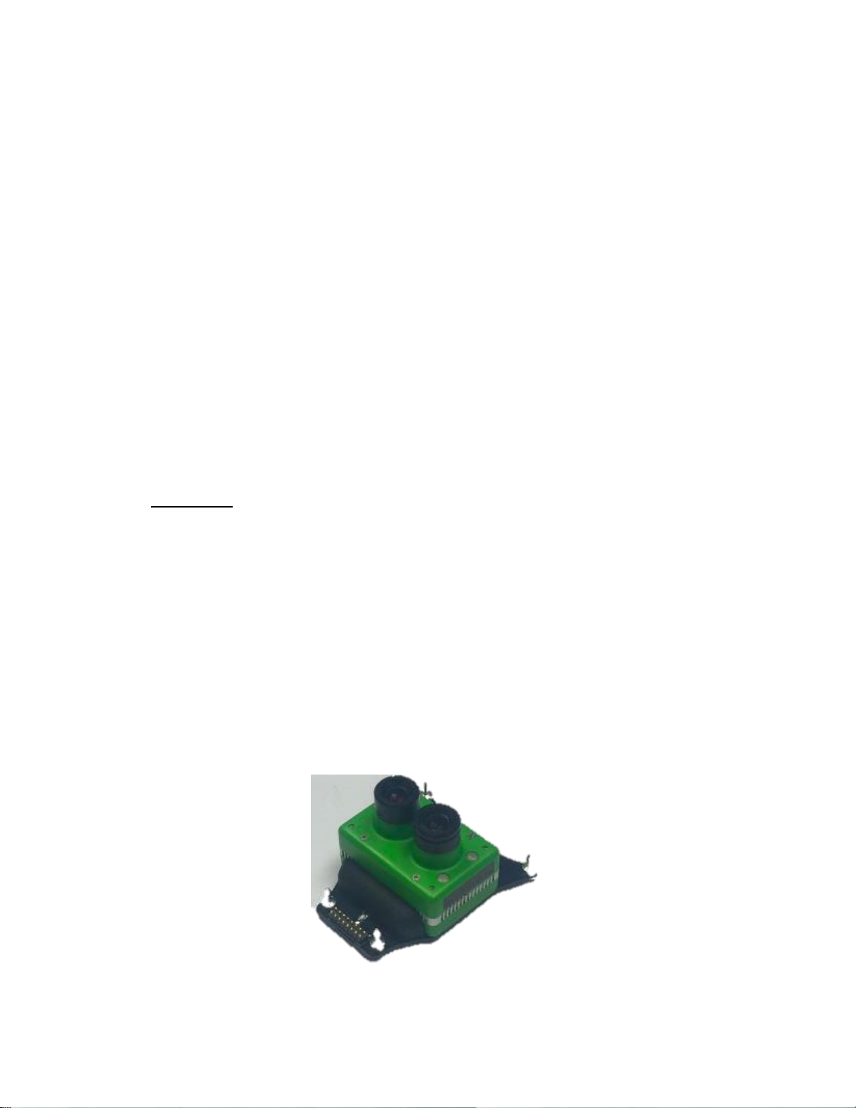
SENTERA DOUBLE 4K, AG AND MAPPING PAYLOAD
Sentera Double 4K Ag and Mapping Payload
Page 45

9-2
Copyright Sentera LLC 2018
Install the Sentera Double 4K payload by snapping it into the PHX plugand-play payload bay. Ensure all 4 mounting posts are securely inserted.
Remove any lens caps before flight. Check the lenses for dirt or
contaminants and clean as needed before flight.
The Sentera Double 4K payload will automatically turn on when the aircraft
battery is installed. Once a GPS location is established, the payload will
begin streaming video and is ready to use.
The Sentera Double 4K mapping payload stores high resolution images
and metadata on the SD card inside the camera. The pictures and
metadata can easily be copied off the payload and imported into Sentera
AgVault or OnTop.
To copy the pictures and metadata to your computer you can either pull the
SDcard or you can download them wirelessly while you are still connected
to the PHX by pointing your Windows file explorer to:
\\192.168.143.141\SDcard\snapshots
Type the above address into the address bar, browse to the files, and copy
the pictures and metadata to your computer. Note: your web browser will
probably not work for this, you need to use the file explorer window.
The Sentera Double 4K hosts a webpage that displays more information
about the camera and its operation. While connected to the PHX open a
web browser and type the address (below) into the address bar
http://192.168.143.141:8080
From this webpage you can see your GPS, attitude, camera, and storage
information. You can also use the webpage to browse the SD card.
Page 46
9-3
Copyright Sentera LLC 2018
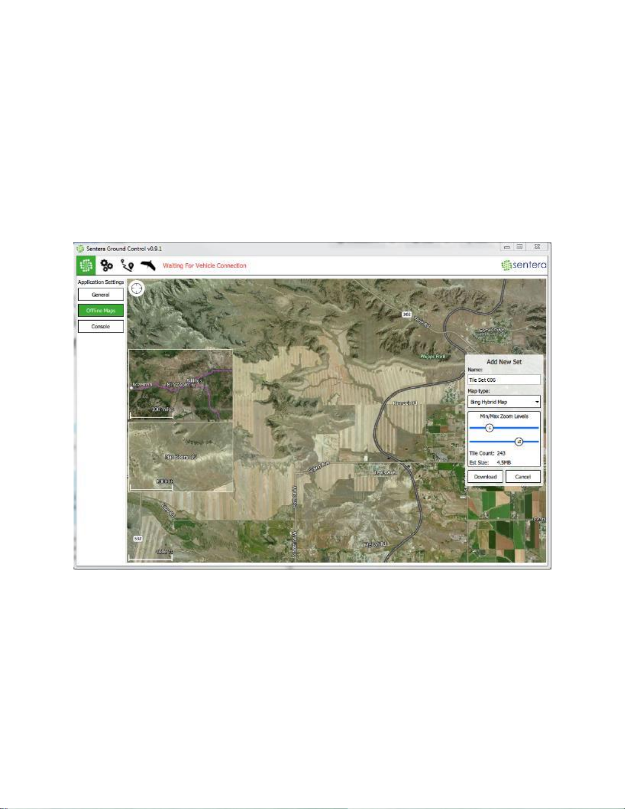
OFFLINE MAPS
Map streaming in Sentera Ground Control works best over a good internet
connection. Where internet connections may be unreliable/unavailable, it is
recommended to pre-load maps before heading out to the field using the
"Offline Maps" screen.
Downloading, saving, and deleting locally saved maps is done in the Offline
Maps tab under the App Settings screen.
Page 47

9-4
Copyright Sentera LLC 2018
BATTERY SWAP PROCEDURE
To perform a battery swap with the PHX the following steps need to occur as stated.
1. The aircraft MUST land via Return mode (RTL). The flight mode can either be triggered by the
low battery failsafe or commanded manually by the user.
2. When the aircraft lands the wings must remain fully seated.
3. Disarm the aircraft.
4. Leave the mission on the vehicle when prompted during the disarm sequence.
5. Remove the battery and replace with a new battery.
6. Allow the aircraft to connect to the CommsBox/Sentera Ground Control
7. The resume mission slider will appear on the fly screen with text dialog that asks if you would
like to re-plan the mission starting at the last waypoint flown. Slide to confirm and the mission
will regenerate with the updated waypoint info.
8. Perform the preflight checklist.
9. Launch.
If the wings come disconnected from the fuselage during landing the following process can be
performed to perform a battery swap.
1. Make note of last flown waypoint. This will be used later to determine where to send the
aircraft to after changing batteries.
2. Land the aircraft.
3. Disarm the aircraft.
4. Leave the mission on the vehicle.
5. Remove the battery and install the new one.
6. Connect to the CommsBox/Sentera Ground Control. The mission that was just flown should
appear.
7. Perform the pre-flight checklist.
8. The resume mission slider may appear. Close the slider box if this is the case.
9. Press the action button and select start mission.
10. Start the mission as normal.
11. Allow the aircraft to tag the first waypoint and ensure the camera is triggering.
12. Select the last waypoint you noted in step 1.
a. NOTE: ensure the waypoint you select will cover the rest of the survey area from where
the aircraft left off to ensure there are no missing photos.
13. Set that waypoint as the active waypoint.
14. Finish the mission.
Page 48

10-1
Copyright Sentera LLC 2016
SECTION 10: SAFETY TIPS
BATTERY USE - PRECAUTIONS
!! WARNING !!
Lithium polymer cells and battery packs may get hot, explode or ignite and cause serious
injury if not properly handled:
1. Do not place the battery in or near fire or heat the battery.
2. Do not reverse polarity on any wires connecting to the battery.
3. Do not connect the positive terminal and negative terminal of the battery to each other
with any metal or conductive object. Do not attempt to remove the debris from the
battery connector with a conductive object.
4. Do not pierce the battery with nails, strike the battery with a hammer, or otherwise
subject it to strong impacts or shocks.
5. Do not expose the battery to water or salt water.
6. Do not disassemble or modify the battery.
7. Do not place or store the battery inside cars in hot weather.
8. Immediately discontinue use of the battery if, while using, charging or storing the
battery, the battery emits an unusual smell, feels hot, changes color or shape, or
appears abnormal in any other way.
9. In the event the battery leaks and the fluid gets into one’s eye, do not rub the eye.
Rinse well with water and immediately seek medical care. If left untreated, the battery
fluid could cause damage to the eye.
10. Use only the battery charger provided with the PHX.
11. Do not attach the battery directly to any other power source.
!! WARNING !!
PROHIBITED MANEUVERS
The PHX autopilot system will not allow users to perform any maneuvers
outside of its flight envelope during normal operation.
PROPELLER SAFETY - PRECAUTIONS
WARNING: use caution around the propeller whenever the UAV is not
“Disarmed”. Wear eye protection during hand launch to avoid dust blowing
into your eyes.
Page 49

10-2
Copyright Sentera LLC 2016
This page intentionally blank.
 Loading...