


SenTech EAS AQUILA receiver manual
URB-100 Tuning Guide
T
T
U
U
NII
N
R
R
N
N
X
X
G
G
G
G
UII
U
D
D
E
E
LUCATRON AG
CH-8606 Greifensee, Switzerland Version 2 Page 1

URB-100 Tuning Guide
Table of Contents
Page
1. Basic Description, Receiver Electronics.................................................................................3
1.1. Analog Part.....................................................................................................................3
1.2. Digital Part......................................................................................................................3
1.3.
2. Description of Features............................................................................................................4
2.1. Manually Adjustable RF Gain..........................................................................................4
2.2. Air Synchronization.........................................................................................................4
2.3. Synchronous Demodulator..............................................................................................4
2.4. Beat Note Filter...............................................................................................................4
2.5. Software Click Filter with Adaptive Slope........................................................................4
2.6. Software Spike Blanker...................................................................................................4
2.7.
2.8. Threshold Calculation.....................................................................................................5
2.9. Alarm Thresho l d Margin Settings....................................................................................5
3. Tuning........................................................................................................................................6
3.1.
3.2. Recommended Tools......................................................................................................6
3.3. Receiver Preparatory Steps............................................................................................6
3.4. Receiver Tuning.............................................................................................................. 8
3.5. Alarm Adjustments........................................................................................................12
3.6.
4. Appendix.................................................................................................................................16
4.1.
4.2.
4.3.
4.4. DIL Switch Settings .......................................................................................................19
4.5. Rotary Switch Settings..................................................................................................20
4.6. Test Points....................................................................................................................21
4.7.
4.8.
Power / Alarm Part...........................................................................................................4
Accept Counter...............................................................................................................5
Philosophy......................................................................................................................6
3.3.1. Preparation.........................................................................................................6
3.4.1.
3.4.2.
3.4.3.
3.4.4. DIL Switch Settings..........................................................................................12
Quick Check .................................................................................................................13
3.6.1. Basics ..............................................................................................................13
3.6.2. RF-Gain Check.................................................................................................13
3.6.3.
3.6.4. Signal / Noise Check.........................................................................................15
Technical Specifications................................................................................................16
Tuning Flowchart ..........................................................................................................17
X3 Connector Layout (External Alarm Unit)...................................................................18
Jumper Settings............................................................................................................22
Compressed Overview..................................................................................................23
RF Gain Adjustment............................................................................................ 8
Beat Note Adjustment.......................................................................................10
Signal / Noise Level Check ................................................................................11
Beat Note Check...............................................................................................14
LUCATRON AG
CH-8606 Greifensee, Switzerland Version 2 Page 2
URB-100 Tuning Guide
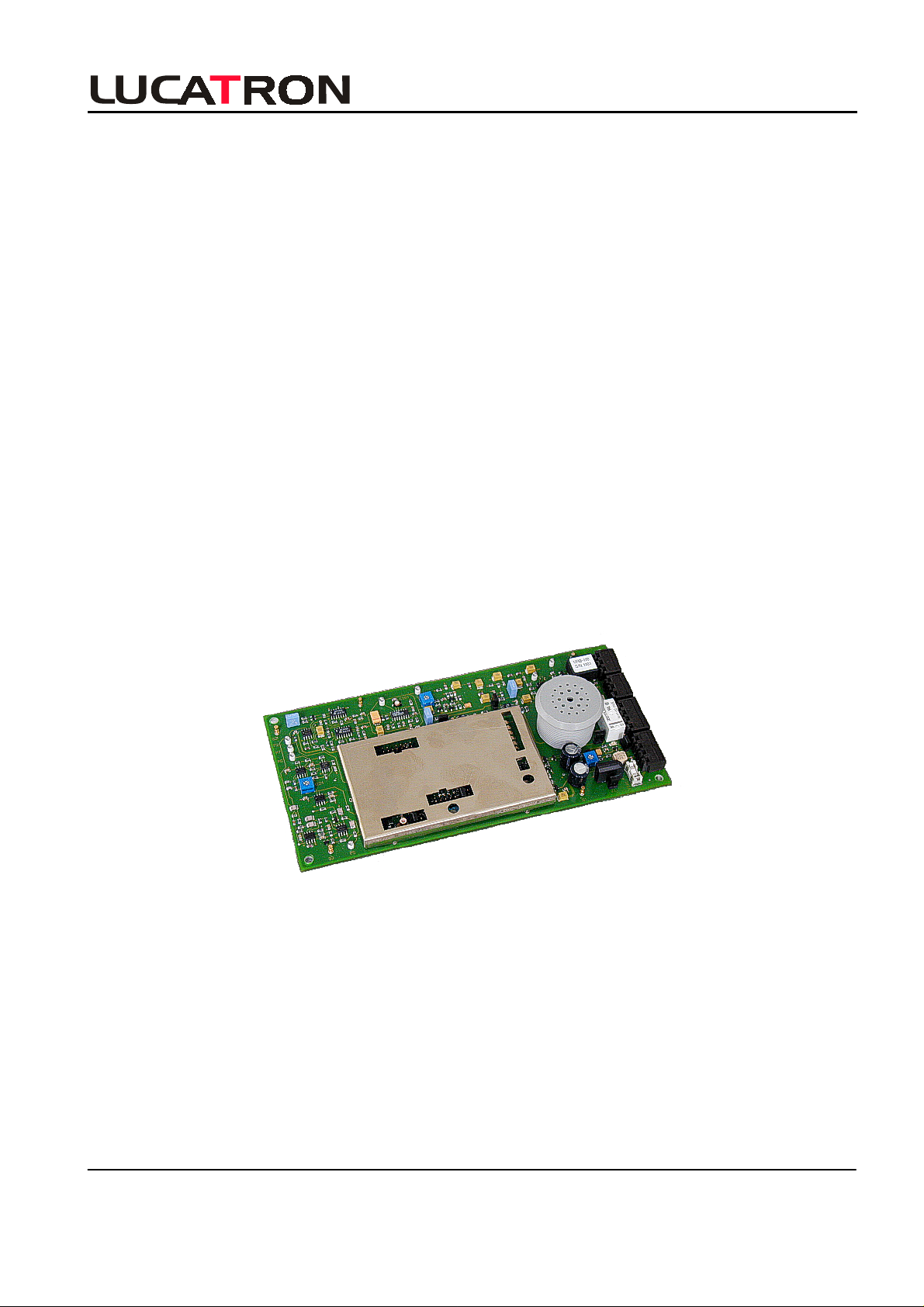
1. Basic Description, Receiver Electronics
The URB-100 receiver board consists of a:
- Analog Part
- Digital Part
- Power / Alarm Part
Analog Part
B
ASICS
P9
P11
Video
GND
X18
Video
Mod
X5
P8
J6
WD R
Digital Part Power / Alarm Part
GND
P2
LF
P7
BeatBeatBeat
P6
Beat
R224
Beatnote
Gain
LF
P5
P1/RF
R112
RF-Gain
J5
P10
Sync
DSP
X7
J7
S1
J3
J2
S3
1
S2
ON OFF
6
4
2
0
8
Receiver Board
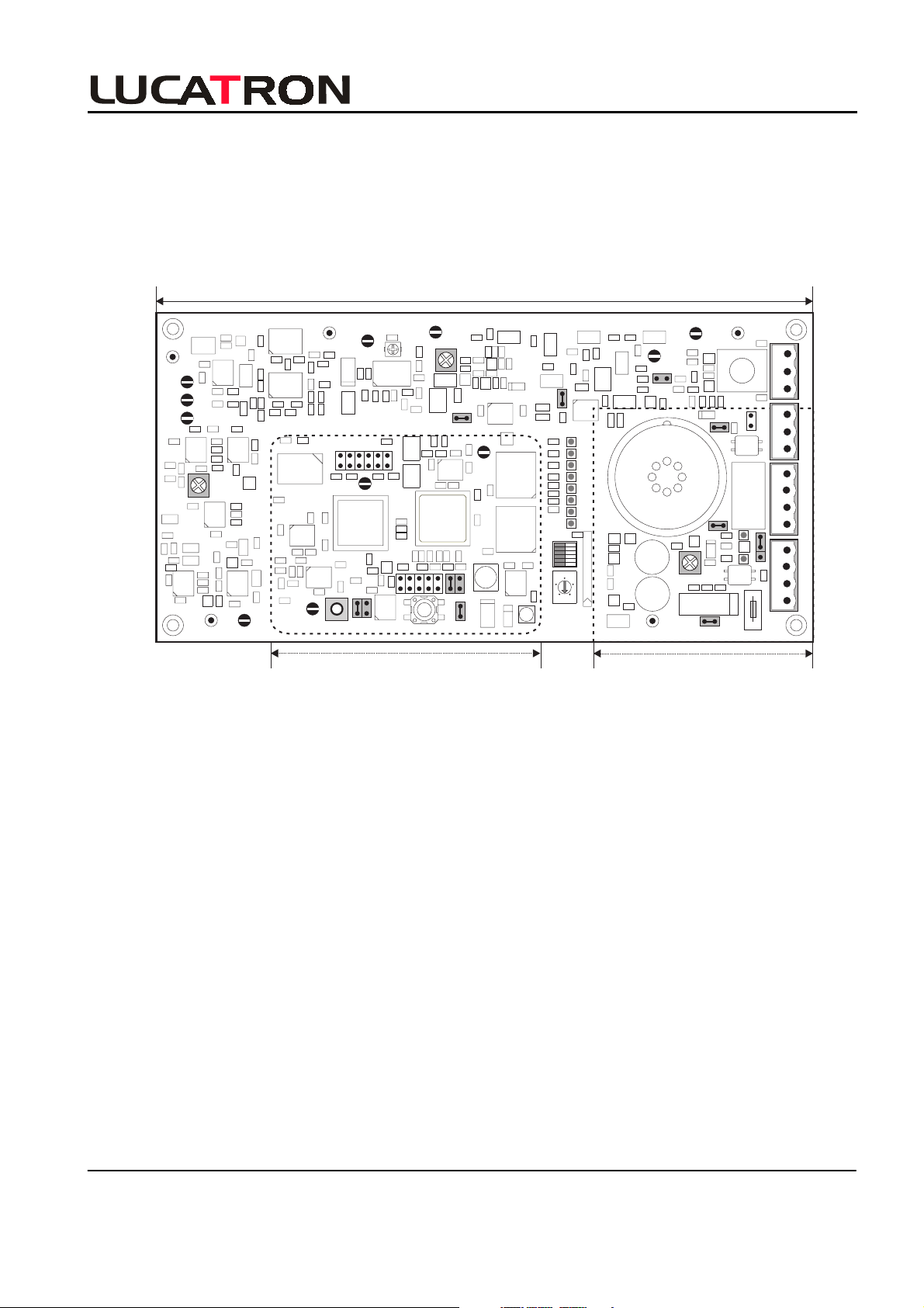
1.1. Analog Part
GNDP3/RF
P4/
RF
J4
X6
J10
J8
Volume
+
R426
+
GNDGND
J1
J9
+-
Fuse
Light (X4) Antenna (X2)
Relay (X3)
Power (X1)
IN NC IN
OUT NC OUT
RLY NC NO GND
(+ +) (- -)
The first input stage amplifies the received RF signal. If this signal is too large, the gain of the first
input stage can be reduced using jumper J4 (Narrow or Wide position).
The next stage is a band-pass filter having a frequency range between 7.2 to 9.2
MHz. If necessary,
the gain of the RF amplifier following the band-pass filter can be changed with potentiometer R112
(RF-Gain). An AGC is not built in, this gives a controlled RF amplification. The amplitude of the tag
signal is pre-regulated by a fixed resistor. The DSP synchronization is done through "air", that is
extracted from the received transmitter signal. A beat note circuit is implemented. This circuit is
inhibiting spikes, radio transmitters and other signals with a very high Q factor.
1.2. Digital Part
The analog tag signal is A / D converted and sampled. The DSP (40 MIPS) filters the demodulated LF
signal and stores the result in a memory. It processes this data and if all alarm criteria are met, it
triggers an alarm.
DIL and rotary octal switches allow adjusting the software parameters and test positions.
LUCATRON AG
CH-8606 Greifensee, Switzerland Version 2 Page 3

URB-100 Tuning Guide
F
EATURES
1.3. Power / Alarm Part
Power is supplied to the receiver electronics by applying 20-24 VDC or 18-20 VAC to the power
supply/power filter part. The integrated filter is used to reduce any interference picked up on the
incoming line from the power supply.
An audible alarm (buzzer) is mounted on the filter part. Outputs for the antenna lamp and an external
alarm are provided.
The volume of the buzzer is adjustable with the Volume potentiometer (R426). A jumper (J10) on the
filter part allows setting the buzzer for continuous or intermittent (optional) tone. The duration of the
audible alarm is about 2 seconds. The duration of the alarm light is about 10 seconds.
2. Description of Features
2.1. Manually Adjustable RF Gain
RF gain needs to be adjusted depending on the antenna type and the aisle width. In tuning mode
S2=7 the RF level is shown on the scope and can be adjusted with (RF Gain) R112. With jumper J4
(RF attenuator) an additional attenuation of 10
dB can be selected.
2.2. Air Synchronization
The sweep information is extracted by a PLL, which is factory adjusted.
2.3. Synchronous Demodulator
The synchronous demodulator has a wide linear input range of 50 mVpp to 600 mVpp and high
conversion gain. If the maximum level is exceeded, then the receiver is muted and the Inhibit
(LED-4) status is on.
2.4. Beat Note Filter
The beat note filter detects carrier signals that are crossing (beating) the system sweep. If the signal
is too strong then DSP blanks it out. The sensitivity is adjustable with (Beat Note Gain) R224. The
beat note filter is active when LED-5 is flashing.
2.5. Software Click Filter with Adaptive Slope
Normally a demodulated tag signal is smooth. When the slewrate of a signal is too fast, this is an
indication of induced noise and will be blanked out by the DSP. Some Hi-Q tags can trigger the filter.
In that case it can be switched off with S3-5. Click filtering is active when LED-6 is flashing.
2.6. Software Spike Blanker
The spike blanker counts the number of samples that are above a certain level. The level is about
50% of the actual alarm threshold. When a preset limit of counts is exceeded then the blocking acts,
thus preventing false alarms in a noisy environment. The blanking is visible on LED-7.
LUCATRON AG
CH-8606 Greifensee, Switzerland Version 2 Page 4

URB-100 Tuning Guide
F
EATURES
2.7. Accept Counter
The accept counter counts the number of consecutive sweeps detecting a tag. If the limit is reached in
both sweeps, then an alarm is generated. The default is 24 sweeps, which gives approximated
ms response time. A faster response time can be selected with S3-3.
300
2.8. Threshold Calculation
The threshold level is based on the signals plus noise averaged over the detection sweep. Under
normal condition this would prevent from triggering an alarm because the threshold rises with
increasing tag signal. The threshold is therefore delayed by approx. 1.5 seconds. This is roughly the
time you have to trigger the alarm at full sensitivity. With the same time delay the system is back to
full sensitivity again.
2.9. Alarm Threshold Margin Settings
With switch S3-1 and S3-2 it is possible to adjust the alarm margin in 4 steps of 3 dB. The actual
margin (peak signal to alarm threshold) is displayed on the LED Levelmeter. The actual alarm
threshold level can be observed on the scope output.
LUCATRON AG
CH-8606 Greifensee, Switzerland Version 2 Page 5

URB-100 Tuning Guide
3. Tuning
3.1. Philosophy
A system will be put into operation as follows:
- First the TX (all) has to be prepared and then tuned.
- Second the RX (s) has to be prepared and then tuned.
- Third set the alarm conditions and make a final check. After this procedure the system is
ready for operation.
If an already installed system needs to be checked, the Quick Check procedure may give a first
indication about the system status.
An overview about the expert tuning and/or quick check procedures is given in a flow chart.
3.2. Recommended Tools
The following instruments are necessary for tuning:
- Multimeter
- Battery-powered oscilloscope with two channels (minimum 20
- 10:1 oscilloscope probes
- Recommended: SMB cable (female
(male
/
male). Radiall P / N R285215 and R191209.
- Recommended: Sweep Span Meter (e.g. XRST-1 crosspoint.nl) or equal. The SSM
displays the minimum, maximum, center and the sweep frequency of a swept RF signal.
/
female, 1meter / 3 feet) plus BNC / SMB adapter
MHz bandwidth).
T
UNING
3.3. Receiver Preparatory Steps
3.3.1. Preparation
• Rem ove power from the RX board by removing the PWR connector at socket X2.
• Ver if y the default j umper J1 to J9 settings (J4 and J6 are under the shield). See table and
layout.
Jumper (J1) (J2) (J3) J4 (J5) (J6/WD) (J7) J8 J9 J10
Setting IN IN IN OUT IN IN IN IN EXT IN
Remark ( ) = Factory use only
RX Default Jumper Settings
Wide/
Narrow
()=Factory
Sound
ON/OFF
Remote
Alarm
Sound
LUCATRON AG
CH-8606 Greifensee, Switzerland Version 2 Page 6
URB-100 Tuning Guide
T
UNING
• Ver if y that t he antenna wires are connected to connector X2. The antenna wires must be
connected to terminal 1 and 3.
GND
P2
P7
P6
LF
BeatBeatBeat
Beat
R224
Beatnote
Gain
P1/RF
R112
RF-Gain
P4/
RF
J5
P10
Sync
J2
J4
GND
P9
Mod
X5
P8
DSP
ON OFF
S3
1
6
4
8
S2
X18
J6
LF
P5
P11
Video
Video
X7
WD R
J7
S1
J3
2
0
Volume
+
R426
+
GNDGND
GNDP3/RF
X6
J10
J8
+-
J1
Relay (X3) Light (X4) Antenna (X2)
J9
Power (X1)
Fuse
RX Default Jumper Settings Layout
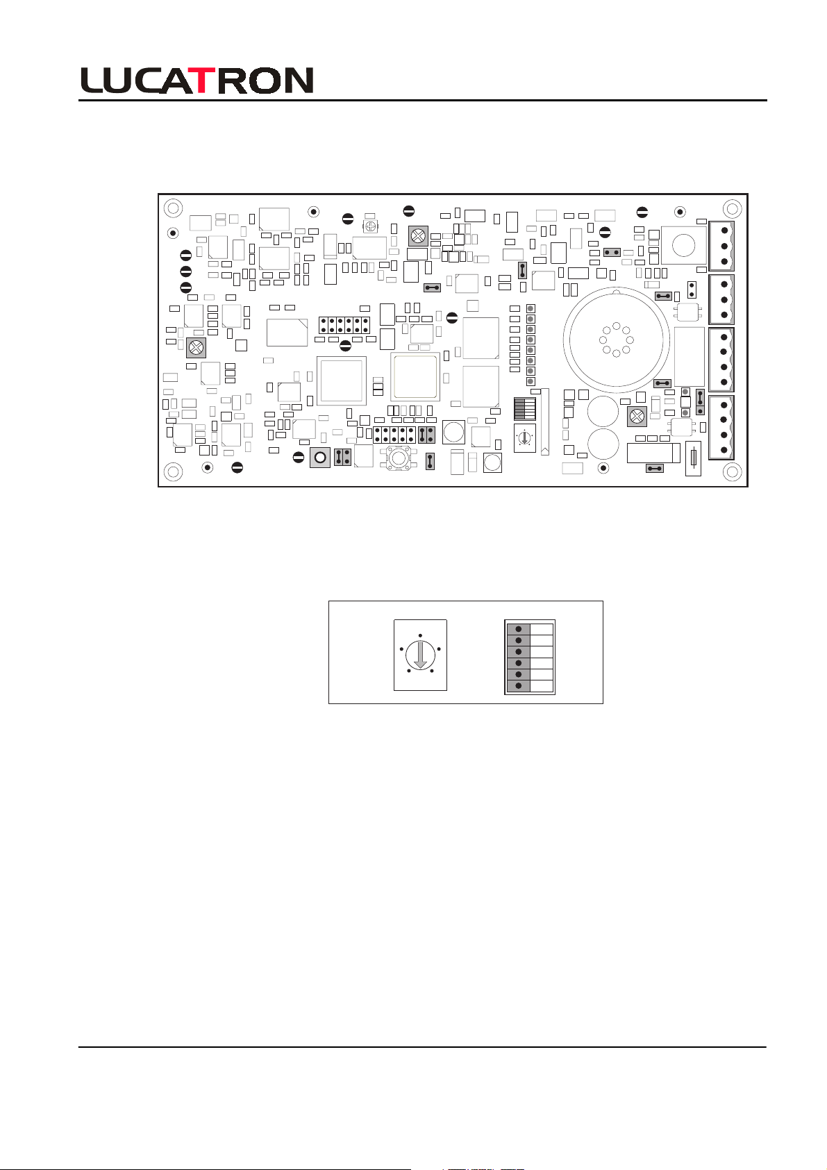
• Set the Rotary switch (S2) to the 0 position and all six (6) DIL (S3) switches to the ON
position. These are the default settings.
IN
NC
IN
OUT
NC
OUT
RLY NC NO GND
(+ +) (- -)
ON OFF
Rotary
Switch
S2
6
4
2
0
DIL
8
S3
S3-6
S3-5
S3-4
S3-3
S3-2
S3-1
Rotary and DIL Switch Default Settings
LUCATRON AG
CH-8606 Greifensee, Switzerland Version 2 Page 7