

Page 1

Hardware & Software Trigger USB 2.0
Color / Monochrome XGA CCD Camera
STC-TC83USB-ASH
STC-TB83USB-ASH
Instruction Manual
Page 2
STC – TC83USB-ASH
!
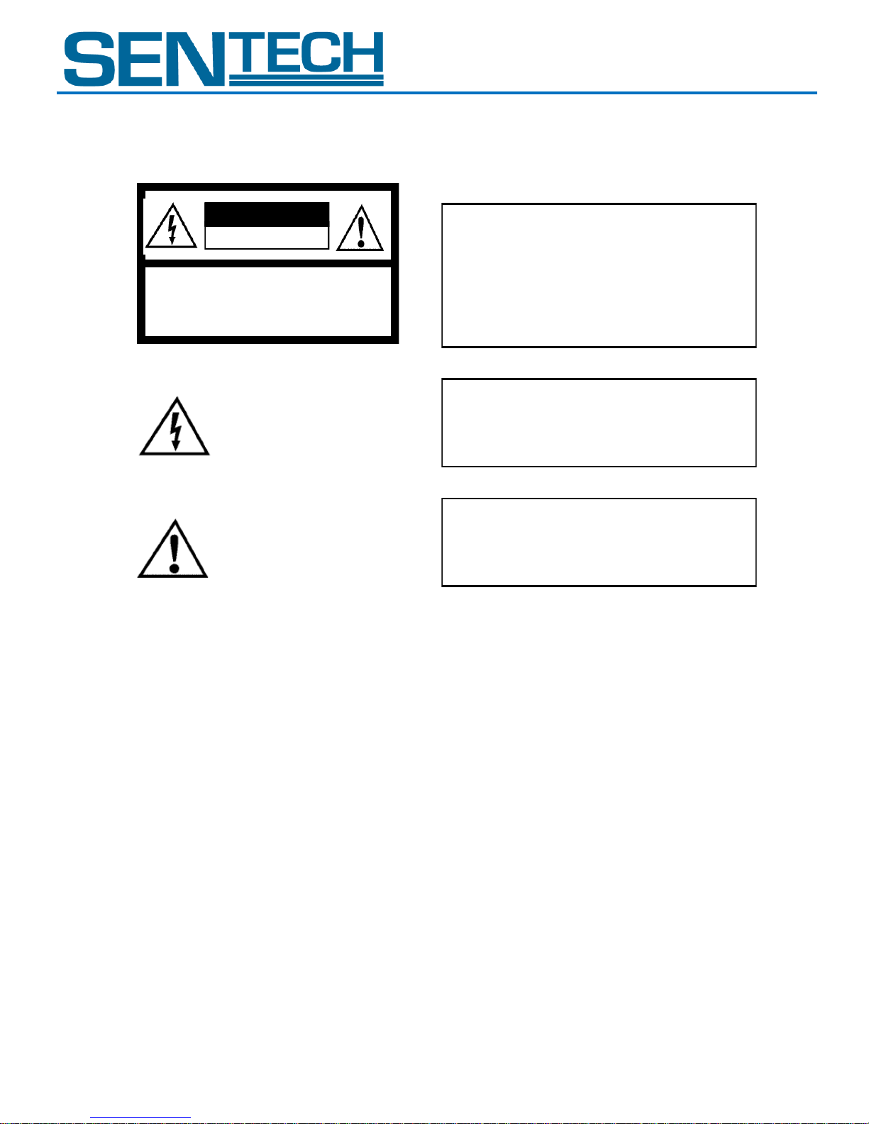
CAUTION
RISK OF ELECTRIC SHOCK
DO NOT OPEN
CAUTION:
TO REDUC E THE RISK OF EL ECTRIC SHOCK, DO NOT
REMOVE C OVER (OR BACK). NO USER SERVICEABLE
PARTS INSIDE.
REFER SERVICING TO QUALIFIED SERVICE PERSONNEL.
Warning:
This equipment generates and uses radio frequency energy and if
not installed and used properly, I.e., in strict accordance with the
instruction manual, may cause harmful interference to radio
communications. It has been tested and found to comply with the
limits for a Class A computing device pursuant to Subpart J of Part
15 of FCC Rules, which are designed to provide reasonable
protection against such interference when operated in a commercial
environment.
For U.S.A.
!
The lightning flash with arrowhead
symbol, within an equilateral triangle,
is i ntended to alert the user t o the
presence of uninsulated “dangerous
vo ltage” wi th in the product ’ s
enclosure that may be of sufficient
ma gnitude to constitute a risk of
electric shock to persons.
The exclamation point within an
equilateral triangle is intended to alert
the user to the presence of important
operating and maintenance (servicing)
i n st r ucti ons in th e l i te rat u re
accompanying the appliance.
Warning:
This equipment generates and uses radio frequency energy and if
not installed and used properly, I.e., in strict accordance with the
instruction manual, may cause harmful interference to radio
communications. It has been tested and found to comply with the
limits for a Class A computing device pursuant to Subpart J of Part
15 of FCC Rules, which are designed to provide reasonable
protection against such interference when operated in a commercial
environment.
For U.S.A.
Warning:
This digital apparatus does not exceed the Class A limits for radio
noise emissions from digital apparatus set out in the Radio
Interference Regulations of the Canadian Department of
Communications.
For Canada
WARNING:
TO PREVENT FIRE OR SHOCK HAZARD, DO NOT EXPOSE
THIS APPLIANCE TO RAIN OR MOISTURE.
Warning:
This equipment generates and uses radio frequency energy and if
not installed and used properly, I.e., in strict accordance with the
instruction manual, may cause harmful interference to radio
communications. It has been tested and found to comply with the
limits for a Class A computing device pursuant to Subpart J of Part
15 of FCC Rules, which are designed to provide reasonable
protection against such interference when operated in a commercial
environment.
For U.S.A.
Warning:
This digital apparatus does not exceed the Class A limits for radio
noise emissions from digital apparatus set out in the Radio
Interference Regulations of the Canadian Department of
Communications.
For Canada
WARNING:
TO PREVENT FIRE OR SHOCK HAZARD, DO NOT EXPOSE
THIS APPLIANCE TO RAIN OR MOISTURE.
Product Specifications 2 of 11 Rev 1.1
STC – TB83USB-ASH
Safety Precautions
Product Precautions
Handle the camera with care. Do not abuse the camera. Avoid striking or shaking it. Improper handling
or storage could damage the camera.
Do not pull or damage the camera cable.
During camera use, do not wrap he unit in any material. This will cause the internal temperature of the
unit to increase.
Do not expose the camera to moisture, or do not try to operate it in wet areas.
Do not operate the camera beyond its temperature, humidity and power source ratings.
While the camera is not being used, keep the lens or lens cap on the camera to prevent dust or
contamination from getting in the CCD or filter area and scratching or damaging this area.
Do not keep the camera under the following conditions:
In wet, moist, and high humidity areas
Use a soft cloth to clean the camera. Use pressured air spray to clean the surface of the glass. DO not
scratch the surface of the glass.
Under hot direct sunlight
In high temperature areas
Near an object that releases a strong magnetic or electric field
Areas with strong vibrations
Page 3

STC – TC83USB-ASH
Product Specifications 3 of 11 Rev 1.1
STC – TB83USB-ASH
Copyright & Disclaimer
Sensor Technologies America, Inc. (DBA Sentech America) believes the contents and specifications of its website, catalog,
documentation and ads are correct; however, Sentech America provides no representation or warranty regarding such information or
products(s) contained therein. It is requested that Sentech America be given appropriate acknowledgement in any subsequent use of
such work by a third party.
While every effort has been made to ensure that the details contained in Sentech America’s website and all documentation are correct
and up-to-date, Sentech America assumes no liability, legal or otherwise for any errors in listings, specifications, part numbers,
process, software or model applications. Sentech America reserves the right to change specifications, product descriptions, product
quality, pricing and application at any time without prior written or oral notice. Any party using such information assumes all risk for
any and all damaged caused to themselves, a third party and/or property by virtue of incorrect information and/or failure of these
products. By installing and/or using a Sentech America software development kit or other similar product and/or information obtained
from Sentech America’s website, catalog, documentation or ads, you hereby accept and understand these stated terms and conditions.
Page 4
STC – TC83USB-ASH
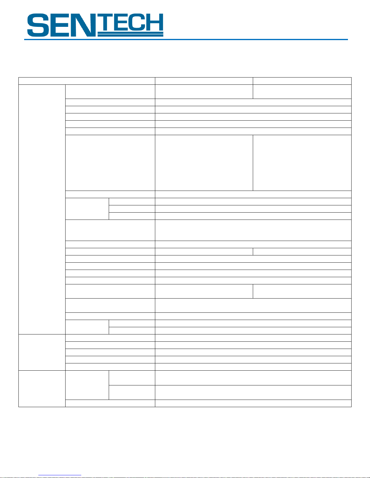
Product
STC-TC83USB-ASH
STC-TB83USB-ASH
Electronic
Specifications
Imager
1/3” Interline XGA Color
Progressive CCD: ICX204AK
1/3” Interline XGA Monochrome
Progressive CCD: ICX204AL
Total Picture Elements
1077 (H) x 788 (V)
Effective Picture Elements
1034 (H) x 779 (V)
Chip Size
5.80 (H) x 4.92 (V) mm
Cell Size
4.65 (H) x 4.65 (V) µm
Scanning System
Progressive
Scanning Methods
Full Scanning, 1/1 Partial
Scanning, ½ Partial Scanning, ¼
Partial Scanning, Variable Partial
Scanning
Full Scanning, 1/1 Partial
Scanning, ½ Partial Scanning, ¼
Partial Scanning, Variable Partial
Scanning, Binning, Binning 1/1
Partial Scanning, Binning ½
Partial Scanning, Binning ¼
Partial Scanning, Binning Variable
Partial Scanning
Pixel Frequency
29.5 MHz
Maximum
Frame Rate
Full Scanning
29.18 fps
½ Partial
60.02 fps
¼ Partial
120.35 fps
Resolution
1024 (H) x 768 (V) (Full Scanning)
1024 (H) x 344 (V) (1/2 Partial Scanning)
1024 (H) x 136 (V) (1/4 Partial Scanning)
S/N Ratio (Standard Deviation)
≤ 10 digit (Factory Default Gain Setting)
Minimum Scene Illumination
1.5 Lux at F1.2
0.5 Lux at F1.2
Sync. System
Internal
Electronic Shutter
Auto / Manual (Software Selectable)
Gain
Auto / Manual (Software Selectable)
Gamma
Manual (Software Selectable)
White Balance
Auto / Manual / One shot
(Software Selectable)
-
Trigger Mode
Free-run / Edge Preset Trigger / Pulse Width Trigger / Start & Stop
Trigger (Software selectable)
Input / Output
USB2.0 High Speed
Power
Supply
Input Voltage
+5V through USB connector or 12Pin connector
Consumption
Less than 330 mA
Mechanical
Specifications
Dimensions
51 (W) x 51 (H) x 35.7 (D) mm
Lens Mount
CS Mount
Input / Output Connector
12 Pin Connector (Hirose) / 2.5 mm Pin Jack
Tripod
2 screws on the bottom plate
Weight
Approximately 130 g
Environmental
Conditions
Temperature
and Humidity
Operational
Temperature: 0 to 40⁰C;
Relative Humidity: 0 to 85% (No Condensation)
Storage
Temperature: -30 to 65⁰C;
Relative Humidity: 0 to 90% (No Condensation)
RoHS
RoHS Compliant
Product Specifications 4 of 11 Rev 1.1
STC – TB83USB-ASH
I. Specifications
A. Electronic Specifications / Mechanical Specifications / Environmental Conditions
Page 5
STC – TC83USB-ASH
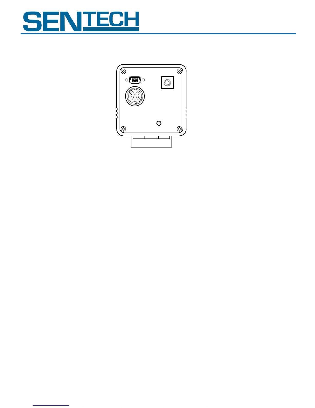
(1)
(2)
(3)
(4)
Product Specifications 5 of 11 Rev 1.1
STC – TB83USB-ASH
B. Connector Specifications
1. USB Connector (Mini B USB Connector)
Please connect the USB cable to this connector only while using the software trigger function or while
using this camera without the trigger function.
If the hardware trigger function is used with the camera including any signal output, please connect the
cable to the 12 pin connector.
Note 1: DO NOT connect the USB cable to its connector when the USB signals in the 12 pin connector
are in use.
Note 2: It is possible to connect lock the cable to the case with screws.
Page 6
STC – TC83USB-ASH
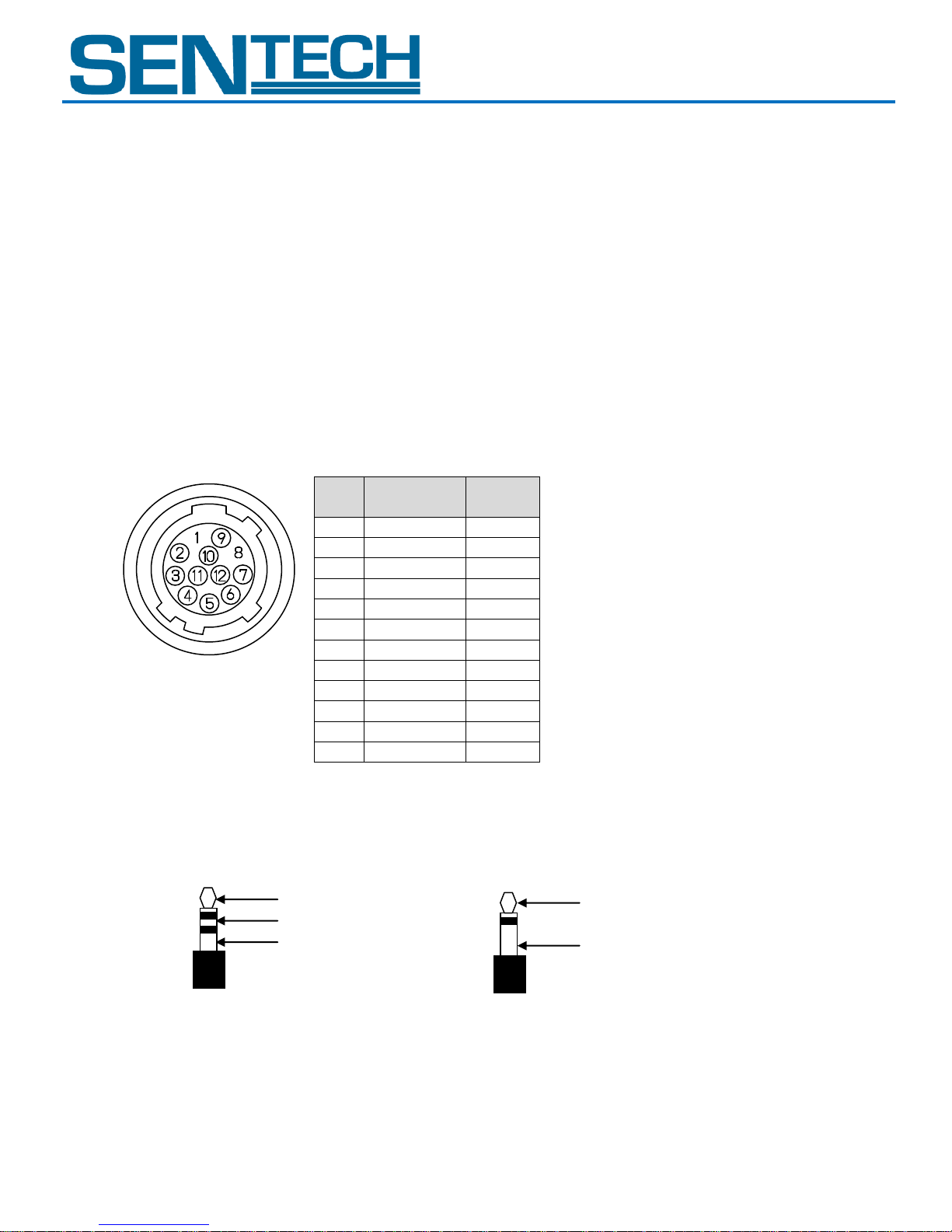
No.
Signal
Type
In / Out
1
GND
2
+5V DC
3 USB D-
4
USB D+
5
IO 0 GND
6
IO 0
In
7
IO 3
Out
8
IO 3 GND
9
IO 1 GND
10
IO 1
In
11
IO 2
Out
12
IO 2 GND
IO2 (Out)
GND
IO1 (In)
IO2 (Out)
GND
Stereo Pin Jack
Mono Pin Jack
Product Specifications 6 of 11 Rev 1.1
STC – TB83USB-ASH
2. 12 Pin Connector
CAUTIONARY NOTE:
a. When the USB signals in the 12 pin connector are in use
1) Please make sure that the cable which connects to the 12 pin connector is an authorized USB2.0
cable. Do not use a cable that is not certified as a standard USB 2.0 cable.
2) Please DO NOT use the USB signal in the 12 pin connector and the USB connector at the same
time. Therefore, DO NOT connect a Mini USB cable to the Mini USB Connector, unless the USB
connection of the 12 pin is disabled (Pin 3 and 4).
CAUTIONARY NOTE:
b. When NOT using the USB signals in the 12pin connector
1) Make sure that the cable which connects to the 12 pin connector does not have a USB signal
connection at pin no. 3 and 4.
With the software, please set up pins for
input (IO0 / IO1) and output (IO2 / IO3).
Depending on the jack type, IO1 and IO2 are
connected to the Input / Output power
connector.
3. Input / Output Connector (2.5 mm Pin Jack)
Please set up for the IO1 and IO2, which signal input and output through this connection with the
software.
4. LED
Red light is on then put the lights out shortly after power on the camera. The LED color changes from
red, to orange, then green. The green light is indicates that the camera is working properly.
Page 7
STC – TC83USB-ASH
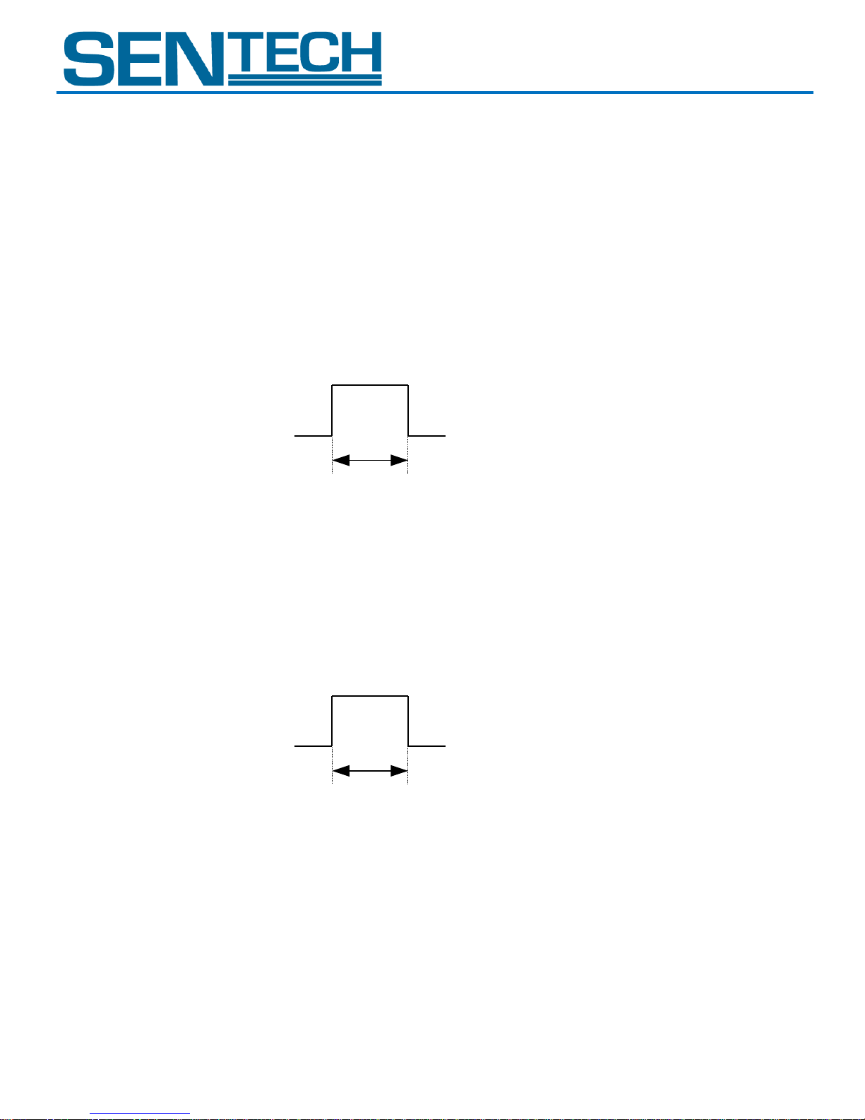
2.5 to 5V
0 to 0.3 V
50 clock to 0.5 seconds
2.5 to 5 V
0 to 0.3 V
50 clock to 0.5 seconds
Product Specifications 7 of 11 Rev 1.1
STC – TB83USB-ASH
C. Input / Output Signals Specifications.
1. Input Signals Specifications
Input signal pins (IO 0 and IO 1) can be configured with “Trigger Input” or “Readout Request” through
the software.
a. Trigger Input Signal Requirements
1) Input Signal Level: High: 2.5 to 5V
Low: 0 to 0.3 V
2) Input Impedance: 10 k Ohm
3) Pulse Polarity: Positive or Negative (selectable by software)
4) Pulse Width: 50 clock to 0.5 seconds
b. Read out request Input Signal Requirements
1) Input signal level: High: 2.5 to 5 V
Low: 0 to 0.3 V
2) Input Impedance: 10 k Ohm
3) Pulse Polarity: Positive or Negative (selectable by the software)
4) Pulse Width: 50 clock to 0.5 seconds
Page 8
STC – TC83USB-ASH
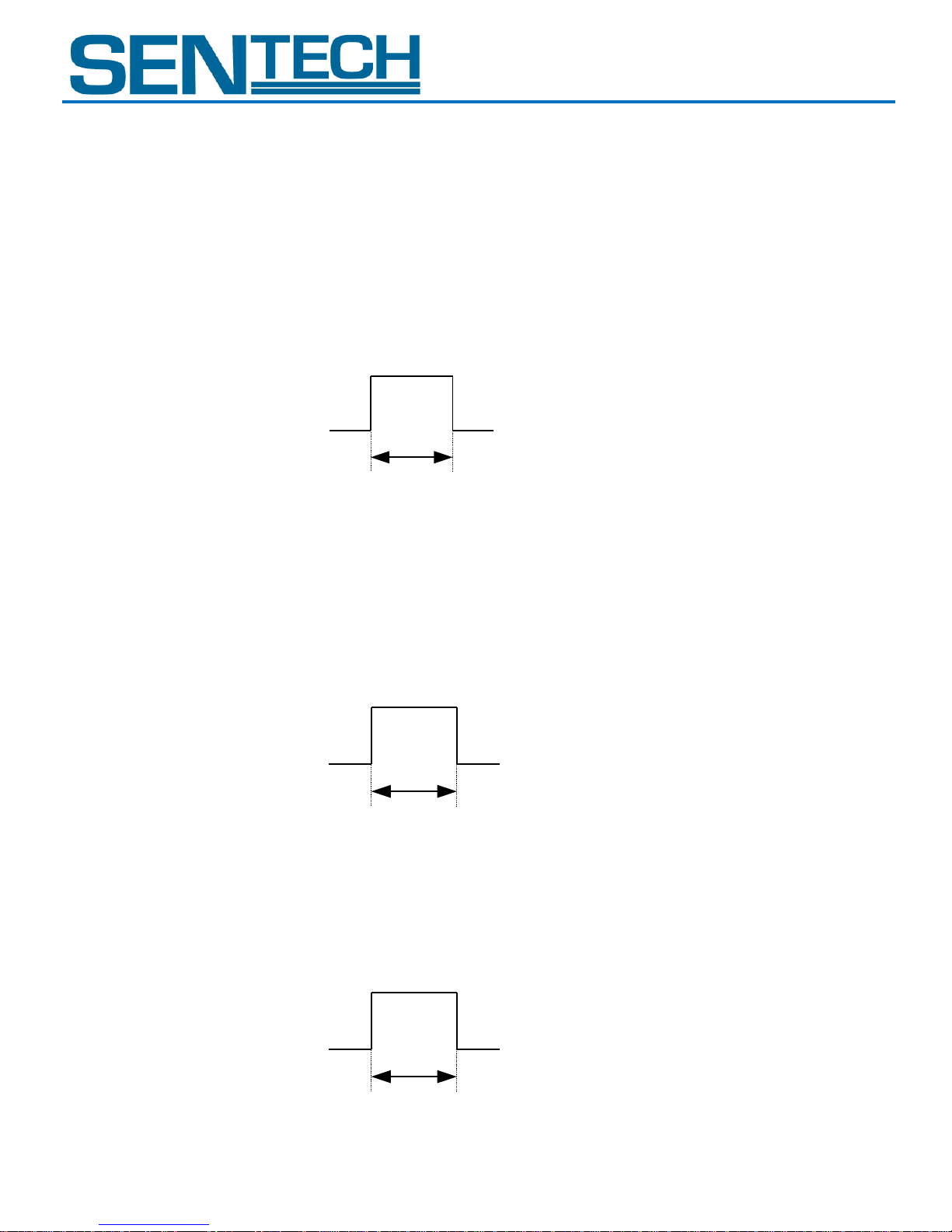
3.3 V
0 V
As same as input trigger signal
3.3 V
0 V
Exposure time + setting time
3.3 V
0 V
Exposure time
Product Specifications 8 of 11 Rev 1.1
STC – TB83USB-ASH
2. Output Signals Specifications
Output signal pins (IO2 and IO3) can be configured with “Strobe Signal Output”, “Trigger Output”, “End
of Exposure” or “End of Transfer” through the software.
a. Strobe (Exposure Time) Output Signal Specifications
1) Output Signal Level: 3.3 Vp-p
2) Output Impedance: High-impedance
3) Pulse Polarity: Positive or Negative (selectable by the software)
4) Pulse Width: Exposure time
b. Strobe (Strobe Signal Setting) Output Signal Specifications
1) Output signal level: 3.3 Vp-p
2) Output impedance: High-impedance
3) Pulse polarity: Positive or Negative (selectable by the software)
4) Pulse width: Exposure time + setting time
c. Trigger (Through) Output Signal Specifications
1) Output signal level: 3.3 Vp-p
2) Output impedance: High-impedance
3) Pulse polarity: Positive or Negative (selectable by the software)
4) Pulse width: As same as input trigger signal
Page 9
STC – TC83USB-ASH
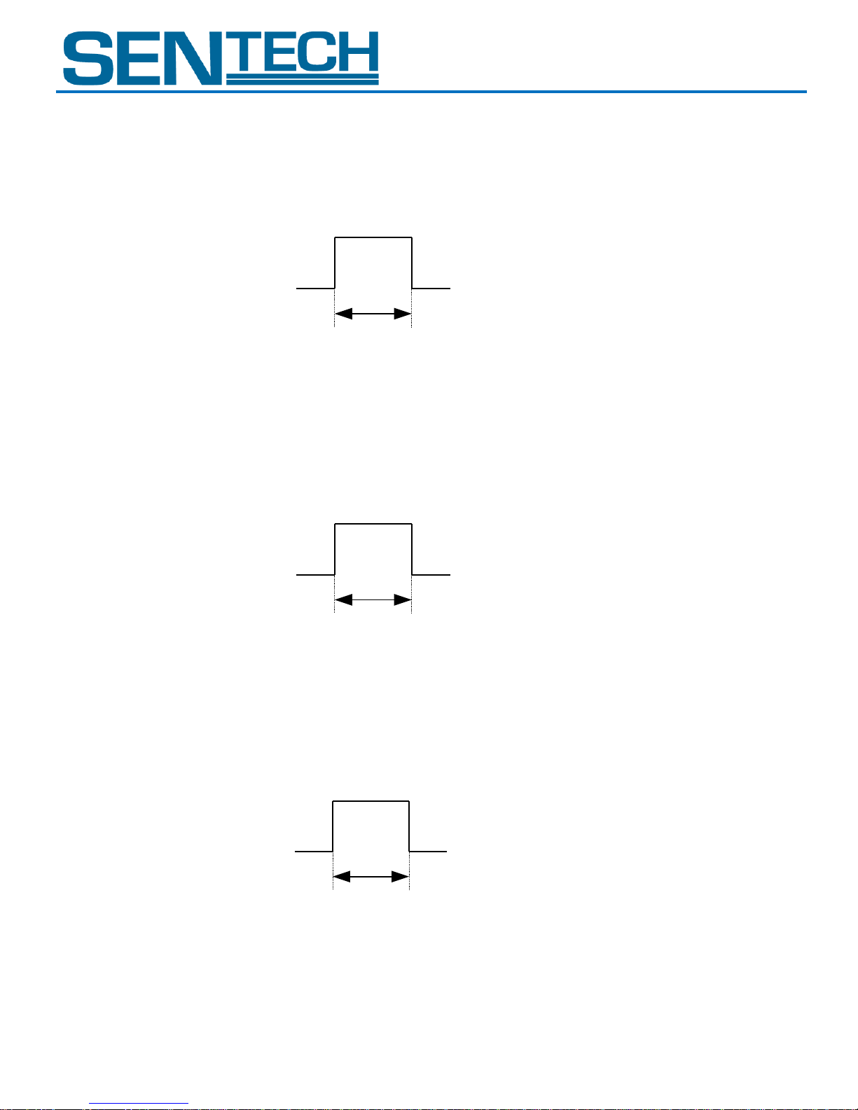
3.3 V
0 V
1 clock to 4094 clock
3.3 V
0 V
1 clock to 4094 clock
3.3 V
0 V
1 clock to 4094 clock
Product Specifications 9 of 11 Rev 1.1
STC – TB83USB-ASH
d. Trigger Output Signal Specifications
1) Output signal level: 3.3 Vp-p
2) Output impedance: High-impedance
3) Pulse polarity: Positive or Negative (selectable by the software)
4) Pulse width: 1 clock to 4094 clocks (selectable by the software)
e. End of Exposure Output Signal Specifications
1) Output signal level: 3.3 Vp-p
2) Output impedance: High-impedance
3) Pulse polarity: Positive or Negative (selectable by the software)
4) Pulse width: 1 clock to 4094 clocks (selectable by the software)
f. End of Transfer Output Signal Specifications
1) Output signal level: 3.3 Vp-p
2) Output impedance: High-impedance
3) Pulse polarity: Positive or Negative (selectable by the software)
4) Pulse width: 1 clock to 4094 clocks (selectable by the software)
Page 10

STC – TC83USB-ASH
Product Specifications 10 of 11 Rev 1.1
STC – TB83USB-ASH
II. Cautions
A. Trigger Input Signal Cycle Time
Set the trigger signal input cycle time to be more than the sum of the exposure time and the video
output, otherwise the following phenomenon may occur:
- Double images
- Excess or abnormal noise
- No video image.
B. Status of the Input Signal Pins at Power-up
All input pins must be set at “low” status when the power is turned on. Otherwise the camera may not
operate properly.
Page 11
STC – TC83USB-ASH
Product Specifications 11 of 11 Rev 1.1
STC – TB83USB-ASH
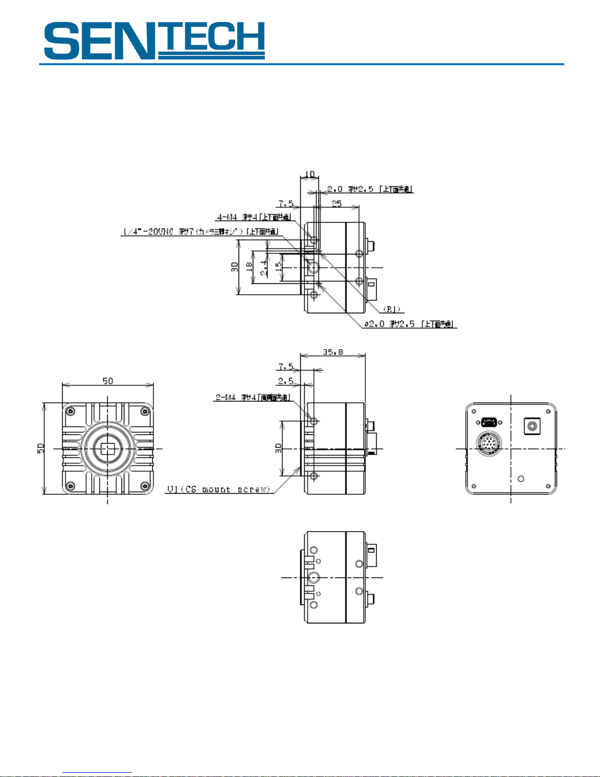
III. Dimensions
Unit: mm
Page 12
STC – TC83USB-ASH
Rev
Date
Changes
Note
1.0
2008/11/28
New document
1.1
2009/03/13
Update
Add the caution of the 12pin connector
Add the S/N ratio (Standard deviation)
Change the right
2009/04/01
Edited English
2009/06/15
Inserted new dimension drawing
STC – TB83USB-ASH
Revisions
Page 13

STC – TC83USB-ASH
STC – TB83USB-ASH
Sensor Technologies America, Inc.
1345 Valwood Pkwy, Suite 320
Carrollton, Texas 75006-6891
TEL (972) 481-9223 FAX (972) 481-9209
URL http://www.sentechamerica.com/
Sensor Technology Co., Ltd.
7F, Harada Center Building
9-17, Naka cho 4chrome
Atsugi-city, Kanagawa
243-0018 Japan
TEL +81-46-295-7061 FAX +81-46-295-7066
URL http://www.sentech.co.jp/
Taiwan Sensor Technology, Inc.
3F-6, No. 9, Aiguo W, Rd,. Jhong Jheng District
Taipei City 100, Taiwan, R.O.C.
TEL 886-2-2383-2331 FAX 886-2-2370-8775
EMAIL: [email protected]
 Loading...