

Page 1

STC-GE83A
STC-GEC83A
User Guide
XGA Color/Monochrome CCD
GigE Vision Camera
Page 2
STC-GE83A
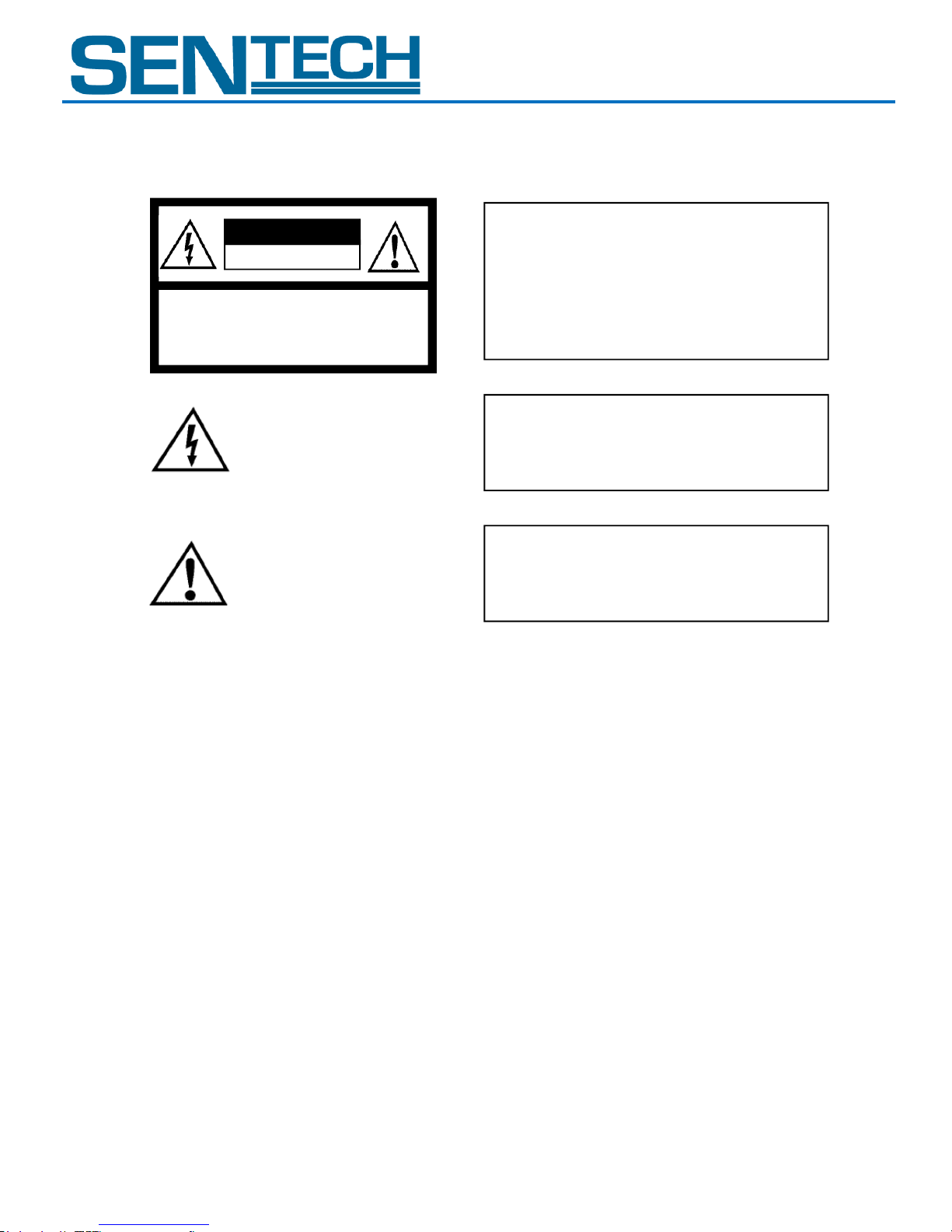
!
CAUTION
RISK OF ELECTRIC SHOCK
DO NOT OPEN
CAUTION:
TO REDUCE THE RISK OF ELECTRIC SHOCK, DO NOT
REMOVE COVER (OR BACK). NO USER SERVICEABLE
PARTS INSIDE.
REFER SERVICING TO QUALIFIED SERVICE PERSONNEL.
Warning:
This equipment generates and uses radio frequency energy and if
not installed and used properly, I.e., in strict accordance with the
instruction manual, may cause harmful interference to radio
communications. It has been tested and found to comply with the
limits for a Class A computing device pursuant to Subpart J of Part
15 of FCC Rules, which are designed to provide reasonable
protection against such interference when operated in a commercial
environment.
For U.S.A.
!
The lightning flash with arrowhead
symbol, within an equilateral triangle,
is intended to alert the user to the
presence of uninsulated “dangerous
voltage” within the product’s
enclosure that may be of sufficient
magnitude to constitute a risk of
electric shock to persons.
The exclamation point within an
equilateral triangle is intended to alert
the user to the presence of important
operating and maintenance (servicing)
instructions in the literature
accompanying the appliance.
Warning:
This equipment generates and uses radio frequency energy and if
not installed and used properly, I.e., in strict accordance with the
instruction manual, may cause harmful interference to radio
communications. It has been tested and found to comply with the
limits for a Class A computing device pursuant to Subpart J of Part
15 of FCC Rules, which are designed to provide reasonable
protection against such interference when operated in a commercial
environment.
For U.S.A.
Warning:
This digital apparatus does not exceed the Class A limits for radio
noise emissions from digital apparatus set out in the Radio
Interference Regulations of the Canadian Department of
Communications.
For Canada
WARNING:
TO PREVENT FIRE OR SHOCK HAZARD, DO NOT EXPOSE
THIS APPLIANCE TO RAIN OR MOISTURE.
Warning:
This equipment generates and uses radio frequency energy and if
not installed and used properly, I.e., in strict accordance with the
instruction manual, may cause harmful interference to radio
communications. It has been tested and found to comply with the
limits for a Class A computing device pursuant to Subpart J of Part
15 of FCC Rules, which are designed to provide reasonable
protection against such interference when operated in a commercial
environment.
For U.S.A.
Warning:
This digital apparatus does not exceed the Class A limits for radio
noise emissions from digital apparatus set out in the Radio
Interference Regulations of the Canadian Department of
Communications.
For Canada
WARNING:
TO PREVENT FIRE OR SHOCK HAZARD, DO NOT EXPOSE
THIS APPLIANCE TO RAIN OR MOISTURE.
Handle the camera with care. Do not abuse the camera; avoid striking or shaking it. Improper handling
or storage could damage the camera.
During camera use, do not wrap he unit in any material. This will cause the internal temperature of the
unit to increase.
Do not expose the camera to moisture, or do not try to operate it in wet areas.
Do not operate the camera beyond its temperature, humidity and power source ratings.
While the camera is not being used, keep the lens or lens cap on the camera to prevent dust or
contamination from getting in the CCD or filter area and scratching or damaging this area.
Do not keep the camera under the following conditions:
Do not pull or damage the camera cable.
In wet, moist, and high humidity areas
Under hot, direct sunlight
Use a soft cloth to clean the camera. Use pressured air spray to clean the surface of the glass. DO not
scratch the surface of the glass.
User Guide 2 Rev 1.01
In high temperature areas
Near an object that releases a strong magnetic or electric field
Areas with strong vibrations
STC-GEC83A
Safety Precautions
Product Precautions
Page 3

STC-GE83A
STC-GEC83A
Copyright & Disclaimer
Sensor Technologies America, Inc. (DBA Sentech America) believes the contents and specifications of its website, catalog,
documentation and ads are correct; however, Sentech America provides no representation or warranty regarding such information or
product(s) contained therein. It is requested that Sentech America be given appropriate acknowledgement in any subsequent use of
such work by a third party.
While every effort has been made to ensure that the details contained in Sentech America’s website and all documentation are correct
and up-to-date, Sentech America assumes no liability, legal or otherwise for any errors in listings, specifications, part numbers,
process, software or model applications. Sentech America reserves the right to change specifications, product descriptions, product
quality, pricing and application at any time without prior written or oral notice. Any party using such information assumes all risk for
any and all damaged caused to themselves, a third party and/or property by virtue of incorrect information and/or failure of these
products. By installing and/or using a Sentech America software development kit or other similar product and/or information obtained
from Sentech America’s website, catalog, documentation or ads, you hereby accept and understand these stated terms and conditions.
User Guide 3 Rev 1.01
Page 4

STC-GE83A
STC-GEC83A
Contents
I. The Connector Specifications ................................................................................................................................ 5-7
A. RJ45 Connector ............................................................................................................................................................... 5
B. Power/IO Connector ....................................................................................................................................................... 6
1. Input Signal ................................................................................................................................................................. 6
2. Output Signal .............................................................................................................................................................. 6
B. DC IRIS lens connector .................................................................................................................................................... 7
II. I/O Circuits ............................................................................................................................................................. 8
III. Camera Output Timing Charts ........................................................................................................................... 9-11
A. The Horizontal Timing ..................................................................................................................................................... 9
1. Color Bayer order (this information is only for STC-GEC83A) ..................................................................................... 9
B. The Vertical Timing .................................................................................................................................................... 9-10
1. Full Scanning ............................................................................................................................................................... 9
2. AOI............................................................................................................................................................................. 10
C. The Transferring Image ................................................................................................................................................. 11
IV. Camera Function Modes ................................................................................................................................ 12-17
A. Normal Mode ................................................................................................................................................................ 12
B. Pulse Width Trigger Mode ....................................................................................................................................... 12-13
1. Timing........................................................................................................................................................................ 12
2. Exposure timing with the positive polarity trigger signal ......................................................................................... 13
3. Exposure timing with the negative polarity trigger signal ........................................................................................ 13
C. Edge Preset Trigger Mode ........................................................................................................................................ 14-15
1. Timing........................................................................................................................................................................ 14
2. Exposure timing with the positive polarity trigger signal ......................................................................................... 14
3. Exposure timing with the negative polarity trigger signal ........................................................................................ 15
D. Edge Preset Trigger Mode (The trigger input while the image is output) ............................................................... 15-16
1. Timing........................................................................................................................................................................ 15
2. Exposure timing with the positive polarity trigger signal ......................................................................................... 16
3. Exposure timing with the negative polarity trigger signal ........................................................................................ 16
E. H Reset Mode ................................................................................................................................................................ 17
V. The Communication Protocol Specifications .................................................................................................... 18-36
A. The Communication Method ........................................................................................................................................ 18
B. The Communication Settings ........................................................................................................................................ 18
C. The Communication Format .................................................................................................................................... 18-19
D. The Camera Control Commands .............................................................................................................................. 20-33
1. The Camera Control Commands List .................................................................................................................... 20-22
2. Description of the Camera Control Commands (Device code: 000000) .............................................................. 23-26
3. Description of the Camera Control Commands (Device code: 100000) ............................................................. 27--33
4. Sequence for the command saves to the EEPROM .................................................................................................. 33
E. GenICam command / Camera command reference table ....................................................................................... 34-36
User Guide 4 Rev 1.01
Page 5
STC-GE83A
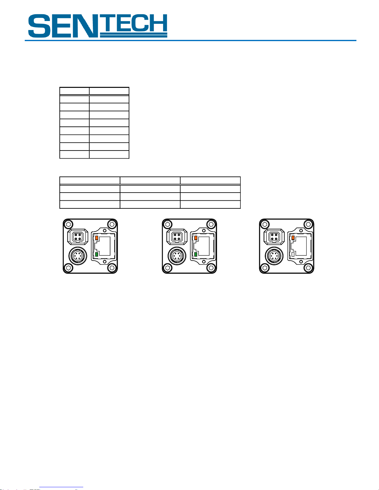
Pin No.
Signal name
1
TA+2TA-3TB+
4 TC+
5
TC-
6 TB-
7
TD+
8 TD-
Green LED
Yellow LED
Status
Green light ON
Orange light ON Power ON
Green light ON
Orange light blinking 1Gb transfering
Light OFF
Orange light blinking 100Mb transfering
STC-GEC83A
I. The Connector Specifications
A. RJ45 connector
Caution: This product is not PoE type. Only apply power (+10.8 to +26.4 V) through the power/IO connector.
Pin assignment
LED information
Power ON the camera Yellow LED: Blinking Green LED: OFF
1Gb transferring Yellow LED: Blinking
100Mb transferring
Please use a 1Gb supported NIC, HUB and LAN cable. Check that the NIC and HUB being used is “1Gb
transferring”.
Damaging or mishandling the CAT5e cable may cause the transferring speed to change from 1Gb to 100Mb.
If this happens, please replace the CAT5e cable.
User Guide 5 Rev 1.01
Page 6
STC-GE83A
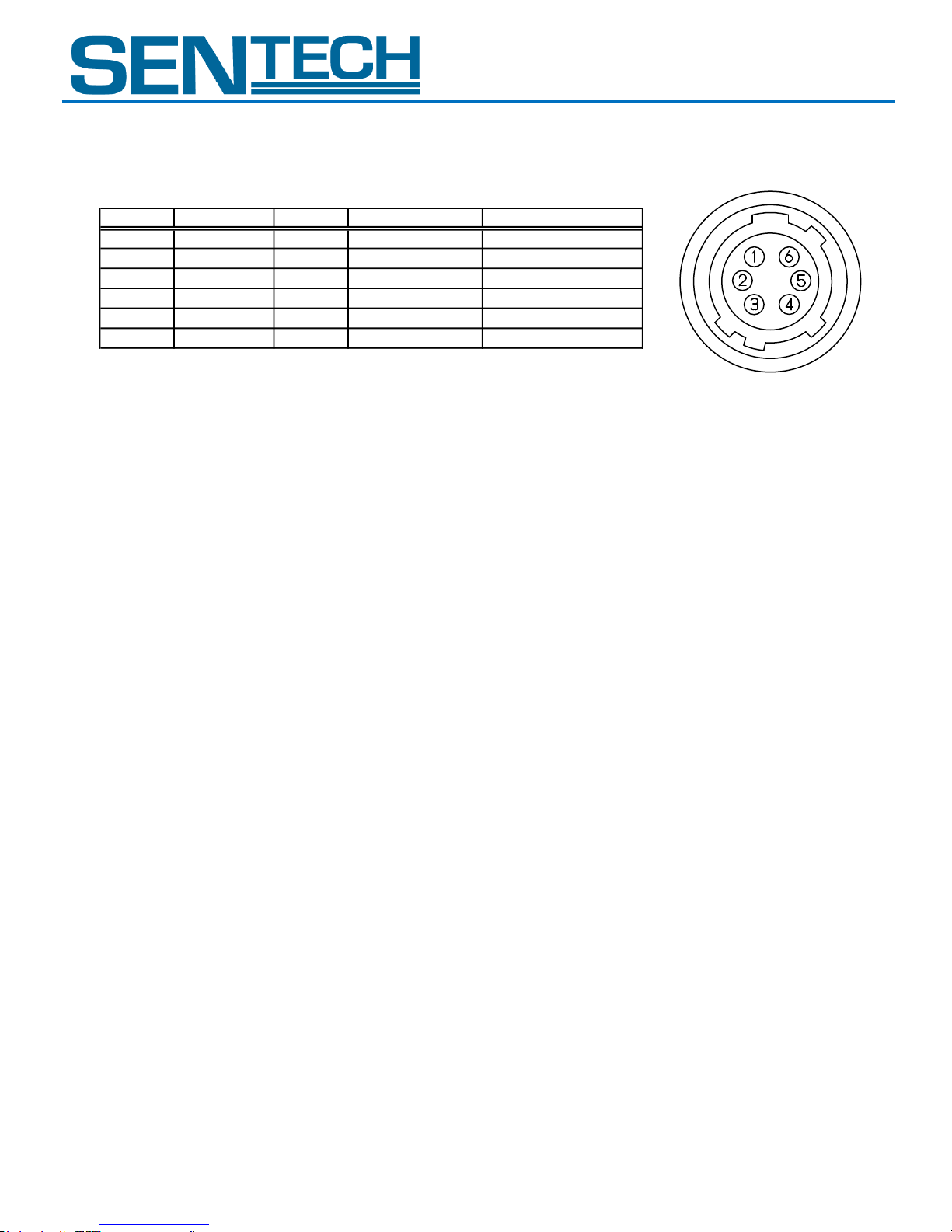
Pin No. Signal name IN/OUT Signals Initial signal
1 GND IN GND
2 IO_Out1 OUT +3.3V LVTTL FrameTriggerWait out
3 IO_Out2 OUT +3.3V LVTTL ExposureActive out
4 TRG_In- IN Isolated -
5 TRG_In+ IN Isolated +
6 POWER IN IN + 10.8 to + 26.4 V
STC-GEC83A
B. Power/IO Connector
Connector: HR10A-7R-6PB (Hirose) or equivalent.
This connector is for DC power input and the input and output signals.
Pin assignment
1. Input Signal
TRG IN: Input the trigger signal
High: +3.0 to +26.4V
Low: Smaller than 1.0V
2. Output Signals
Set the output signals from the power/IO connector.
The following six output signals are selectable with the software or communication:
a. FrameTriggerWait
With the FrameTriggerWait signal, the user can check the camera conditions of the camera exposure and the image output
processing by the trigger signal.
1) High status (3.3V): No processing by the trigger signal. The camera accepts the trigger signal
2) Low status (0V): The camera exposes and the image output processing by the trigger signal
The camera’s default setting is that the input trigger signal is INVALID during the low status for this signal.
In order to start the exposure while the image is being output by the next trigger signal, please change the camera settings
(Device code: 001, Command: 13H) to accept the trigger signal while the image is being output.
Noise may appear on the image when the exposure is initiated while the image is being output. In this case, please change the
“H reset” of the exposure start mode (Device code: 00H, Command: 12H) in order to change the exposure start point to next
HD timing.
b. UserOutput
The status of this UserOutput signal can be changed with the “UserOutputValue”.
c. ExposureActive
The user can check the exposure time with the ExposureActive signal.
1) High status (3.3V): The camera is exposing
2) Low status (0V): The camera is not exposed
d. TriggerAuxiliary
This TriggerAuxiliary signal is the trigger signal.
e. TriggerInternal
This TrigerInternal signal is the trigger signal for the trigger delay time.
f. SensorReadOut
SensorReadOut signal is the FVAL signal (the image output period of the time).
User Guide 6 Rev 1.01
Page 7
STC-GE83A
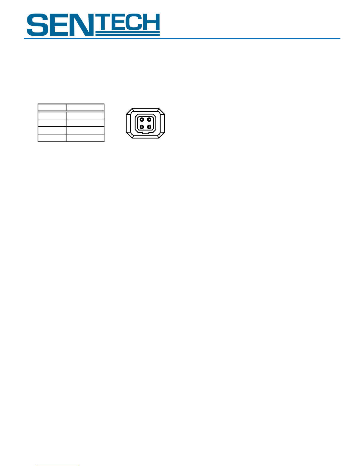
1 2
3 4
Pin No.
Signal name
1
DAMP-
2
DAMP+
3
DRIVE+
4 DRIVE-
STC-GEC83A
g. StrobeSignal
The StrobeSignal signal is the strobe control signal.
C. DC IRIS lens connector
Connector: M1951 (EMUDEN) or equivalent.
Pin Assignment:
User Guide 7 Rev 1.01
Page 8
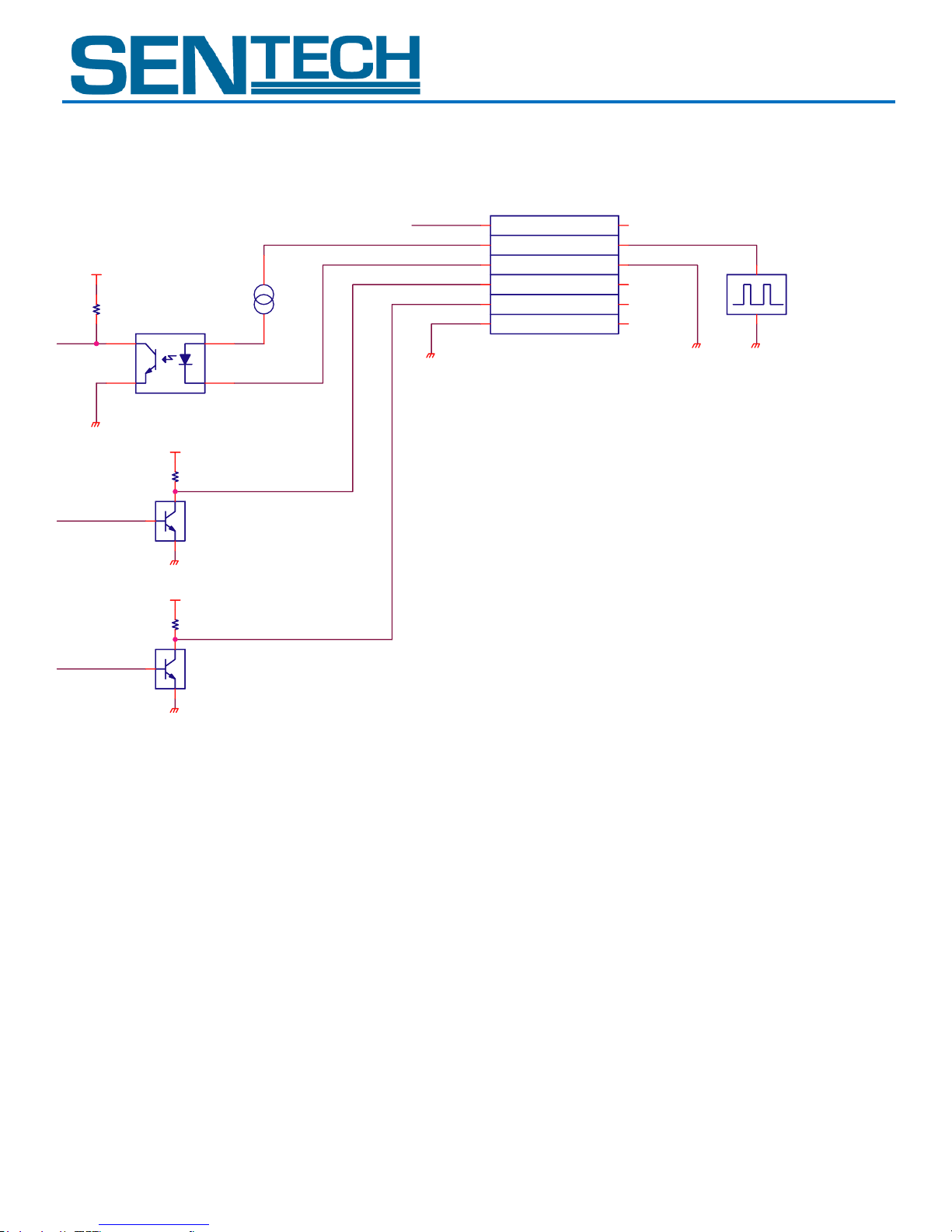
STC-GE83A
+3.3V
+3.3V
+3.3V
TOSHIBA RN1105MFVTOSHIBA RN1105MFV
2
1 3
TOSHIBA TLP181TOSHIBA TLP181
34
6 1
2.2K2.2K
1
2
3
4
5
6
TOSHIBA RN1105MFVTOSHIBA RN1105MFV
2
1 3
1K1K
1K1K
+10.8 to +26.4V
Trigger_In+
Trigger_In-
IO_Out
IO_Out
GND
Customer GND
+3 to +26.4V
3 to 5mA
Trigger Signal
HR10A-7R-6PB (HIROSE)
or equivalent connector
STC-GEC83A
II. I/O Circuits
User Guide 8 Rev 1.01
Page 9
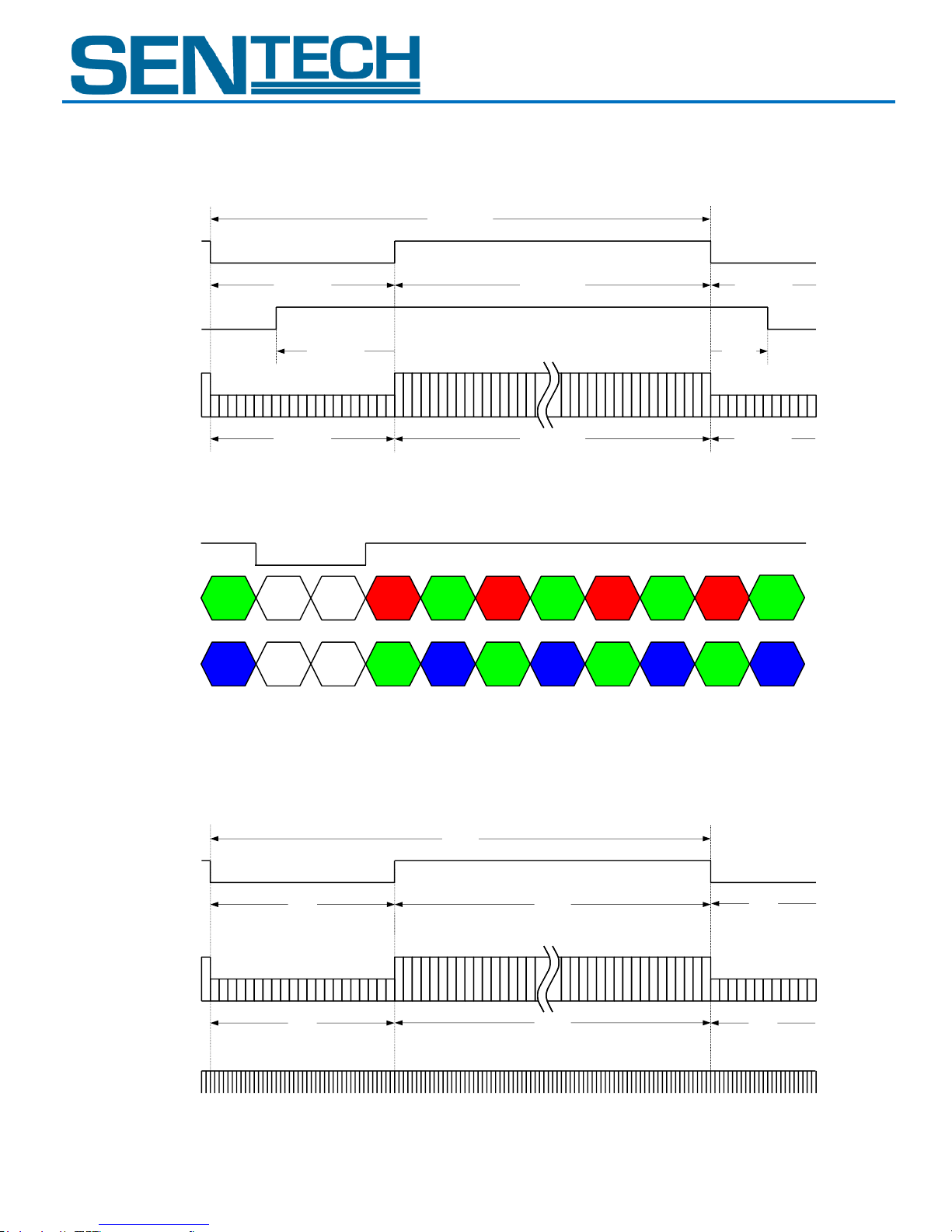
STC-GE83A
R1 Gr1 R2
Gb1 Gb2B1
Gr2
B2
Video out
Line 1
・・・
Video out
Line 2
LVAL
R3
Gb3
Gr3B3・・・
・・・
・・・
・・・・・・
246 CLK1024 CLK
Video out
LVAL
Horizontal blanking
1270 CLK
One horizontal (1H)
1024 CLK246 CLK
246 CLK
Video output
246 CLK
94
CLK
152 CLK
FVAL
28H768H
Video out
FVAL
Vertical blanking
796H
One vertical (1V)
768H28H
28H
Video output
1
2
767
768
28H
LVAL
III. The Camera Output Timing Charts
A. The Horizontal Timing
1. Color Bayer order (This information is only applicable to the STC-GEC83A)
B. The Vertical Timing
1. Full Scanning
User Guide 9 Rev 1.01
1 CLK = 27.1605 nseconds
1 H = 34.493 µseconds, 36.42113 Hz
STC-GEC83A
Page 10
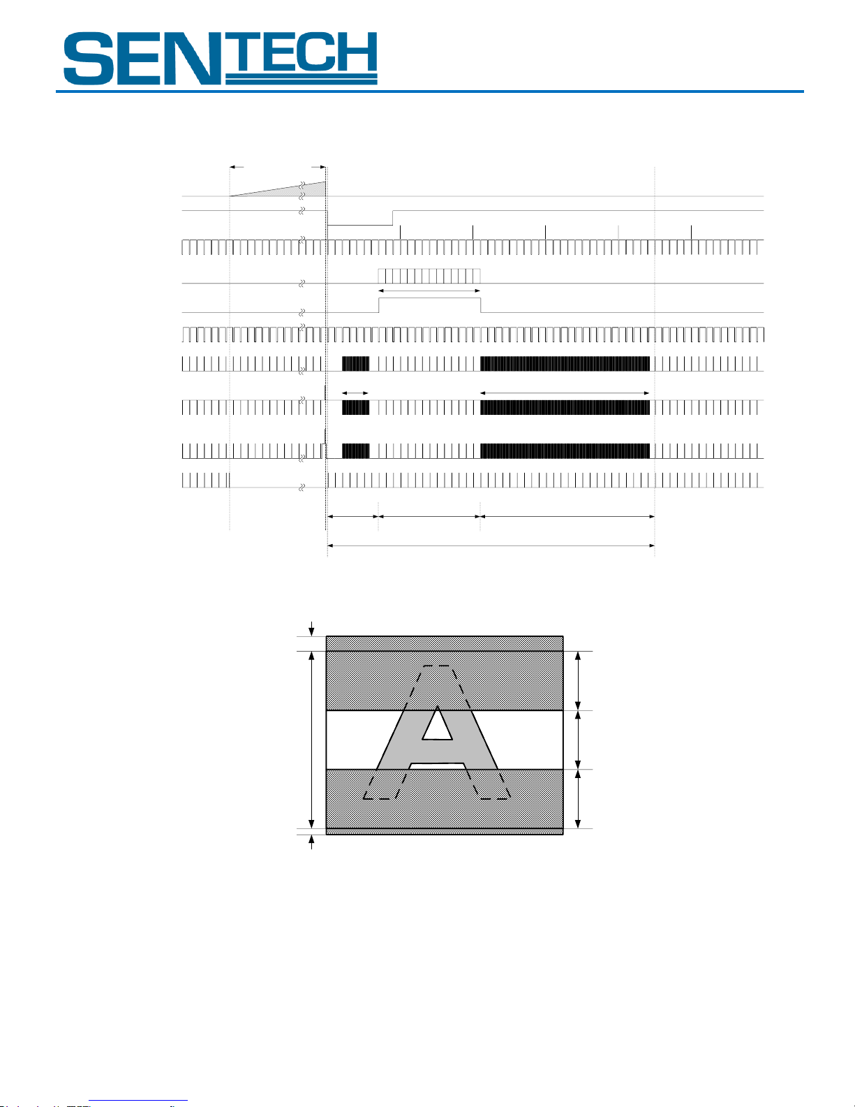
STC-GE83A
Internal HD
Internal VD
Video out
EXT_TRIG
FIX_TRIG
(Common)
10 20 30 40 50
Exposure time
V1
V2
V3
SUB
FVAL
LVAL
Number of the
effective lines [Y]
High speed
transfer [X+a]
High speed transfer [f+g-X-Y]
Blanking (Front)
[BLK_F]
Number of the effective lines [Y]
Total number of the line at 1 frame [TOTAL_LINE]
Blanking (Back)
[BLK_B)
CCD effective
lines
Blanking
(Front)
Effective
lines
Optical black
+
Dummy bit
Blanking
(Back)
Optical black
STC-GEC83A
2. AOI
C.
User Guide 10 Rev 1.01
Page 11
STC-GE83A
Pixel1 of
Data
Pixel2 of
Data
Pixel11 of
Data
Pixe12 of
Data
Pixel21 of
Data
Pixel22 of
Data
STC-GEC83A
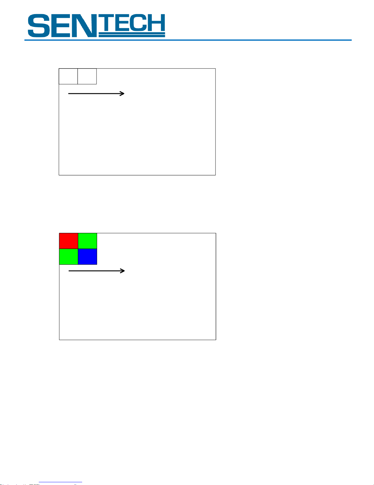
The Transferring Image
STC-GE83A (Monochrome)
Pixeln of Data: The transferring pixel
n: The order number
STC-GEC83A (Color)
Pixelmn of Data: The transferring pixel
m: The line number
n: The order number
User Guide 11 Rev 1.01
Page 12
STC-GE83A
E x p o s u r e
t i m e
I n t e r n a l V D
CCD
e x p o s u r e
V i d e o o u t
Exposure
time
Max. 1H
Internal VD
CCD exposure
Trigger signal
(Positive)
Video out
*Note. 1
*Note. 2
FVAL
IV. Camera Function Modes
A. Normal Mode
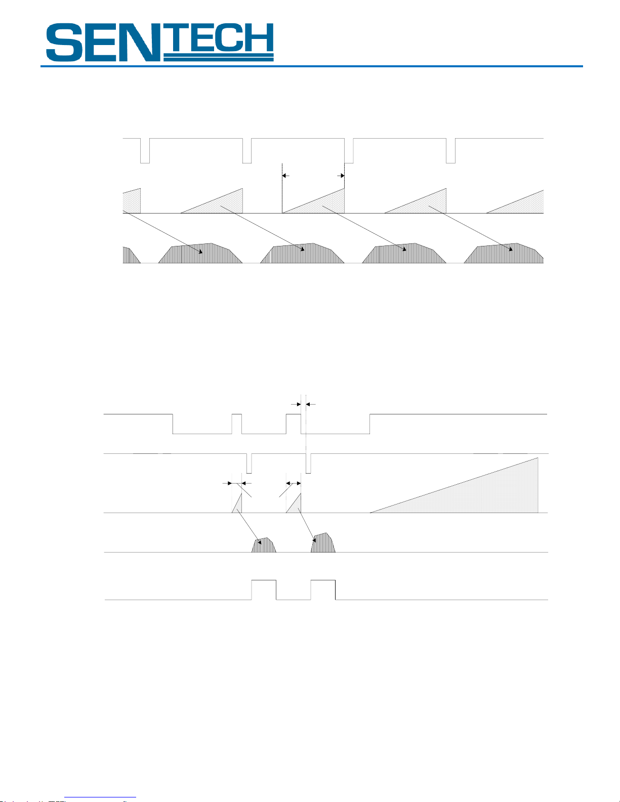
B. Pulse Width Trigger Mode
STC-GEC83A
In this trigger mode with positive polarity, the camera exposure starts at the rising edge of the trigger pulse and stops at the
falling edge of the trigger pulse. Therefore, if positive polarity exposure is selected, the exposure periods are the high states of
the trigger pulse.
1. Timing
Note 1: The video output is going to be V reset by the next internal HD signal immediately after the exposure is finished.
Note 2: The exposure time is set by the pulse width of the trigger signal.
User Guide 12 Rev 1.01
Page 13
STC-GE83A
T1'
SUB
SG
(127 CLK)
Input Trigger signal
Exposure time
Exposure time: T1' = T1 + 127 CLK
T1
30 CLK
Filtering *Note.1
Trigger signal
(With Photocoupler delay)
T1
Less than
5 useconds
T1'
SUB
SG
(127 CLK)
Input Trigger signal
Exposure time
Exposure time: T1' = T1 + 127 CLK
T1
30 CLK
Filtering *Note.1
Trigger signal
(With Photocoupler delay)
T1
Less than
60 useconds
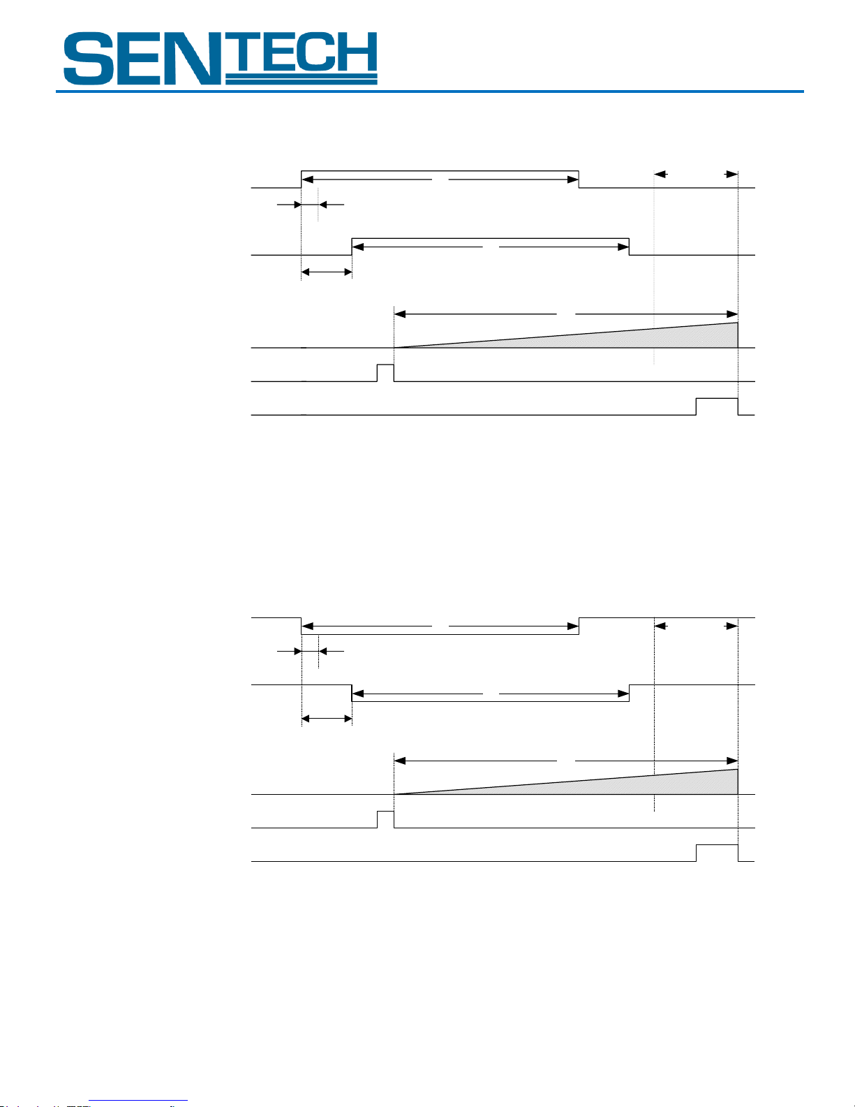
2. Exposure Timing with the Positive Polarity Trigger Signal
Note 1: The trigger signal will be removed by the filtering if the pulse width of the input trigger signal is less than 30 CLK.
Please input a trigger signal with more than 31 CLK pulse width.
Note 2: The exposure will start 110 CLK after the rising edge of the trigger signal.
3. Exposure Timing with the Negative Polarity Trigger Signal
Note 1: The trigger signal will be removed by the filtering if the pulse width of the input trigger signal is less than 30 CLK.
Please input a trigger signal with more than 31 CLK pulse width.
Note 2: The exposure will start 110 CLK after the rising edge of the trigger signal.
STC-GEC83A
User Guide 13 Rev 1.01
Page 14
STC-GE83A
Exposure
time
Max. 1H
Internal VD
CCD exposure
Trigger signal
(Rising edge)
Video out
*Note. 1
*Note. 2
FVAL
Input Trigger signal
Exposure time
T1'
SUB
SG
Exposure time: T1' = Preset exposure time
Filtering *Note.1
30CLK
Trigger signal
(With Photocoupler delay)
Less than
5 useconds
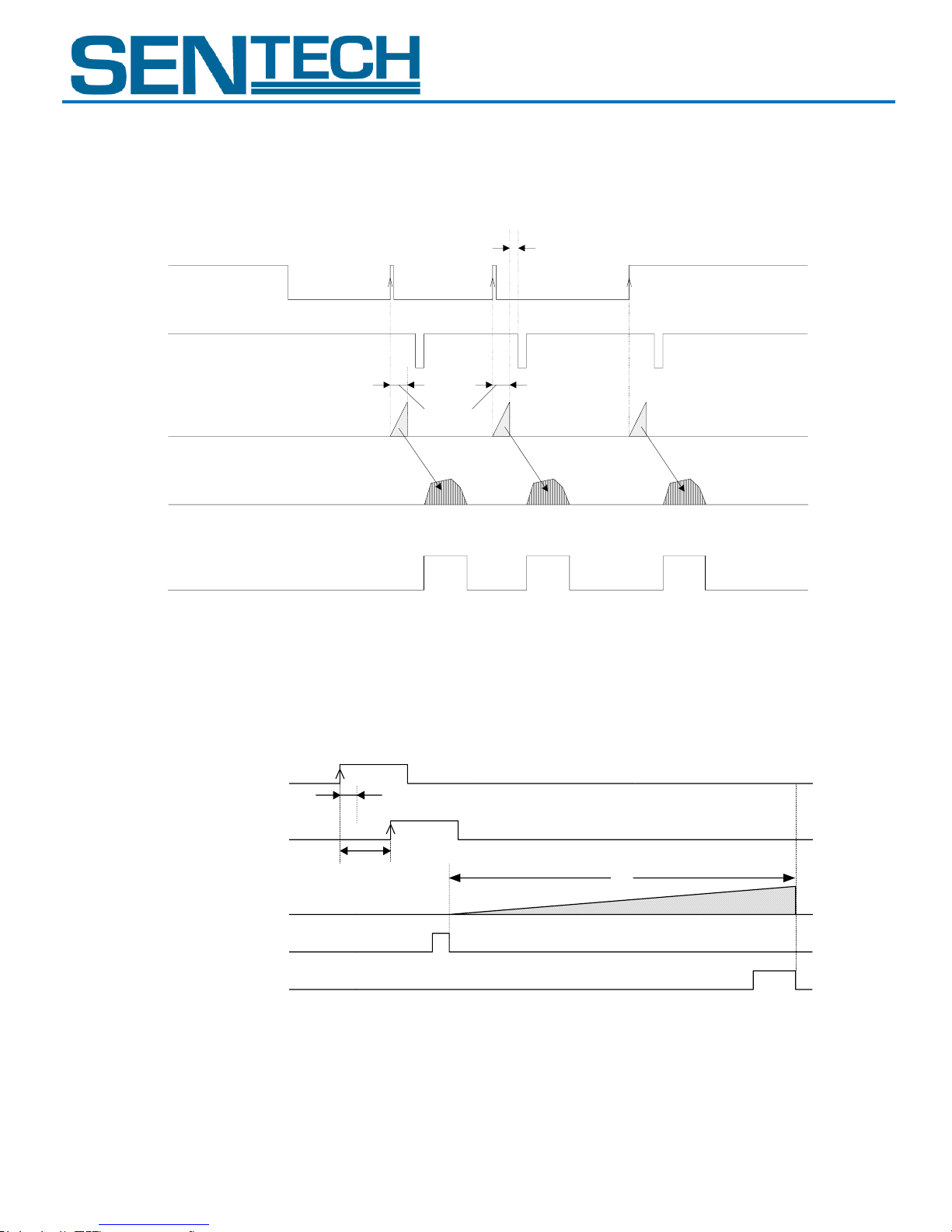
C. Edge Preset Trigger Mode
In this trigger mode, the camera exposure starts at the rising edge of the trigger pulse. The exposure duration time is preset by
the DIP Switch settings.
1. Timing
Note 1: The video output will be V reset by the next internal HD signal immediately after the exposure is finished.
Note 2: The exposure time is set by the preset electronic shutter speed.
2. Exposure Timing with the Positive Polarity Trigger Signal
Note 1: The trigger signal will be removed by the filtering if the pulse width of the input trigger signal is less than 30 CLK.
Please input a trigger signal with more than 31 CLK pulse width.
Note 2: The exposure will start 110 CLK after the rising edge of the trigger signal.
STC-GEC83A
User Guide 14 Rev 1.01
Page 15
STC-GE83A
Input Trigger signal
Exposure time
T1'
SUB
SG
Exposure time: T1' = Preset exposure time
Filtering *Note.1
30CLK
Trigger signal
(With Photocoupler delay)
Less than
60 useconds
Exposure
time
Max. 1H
Internal VD
CCD exposure
Trigger signal
(Rising edge)
Video out
*Note. 1
*Note. 2
FVAL
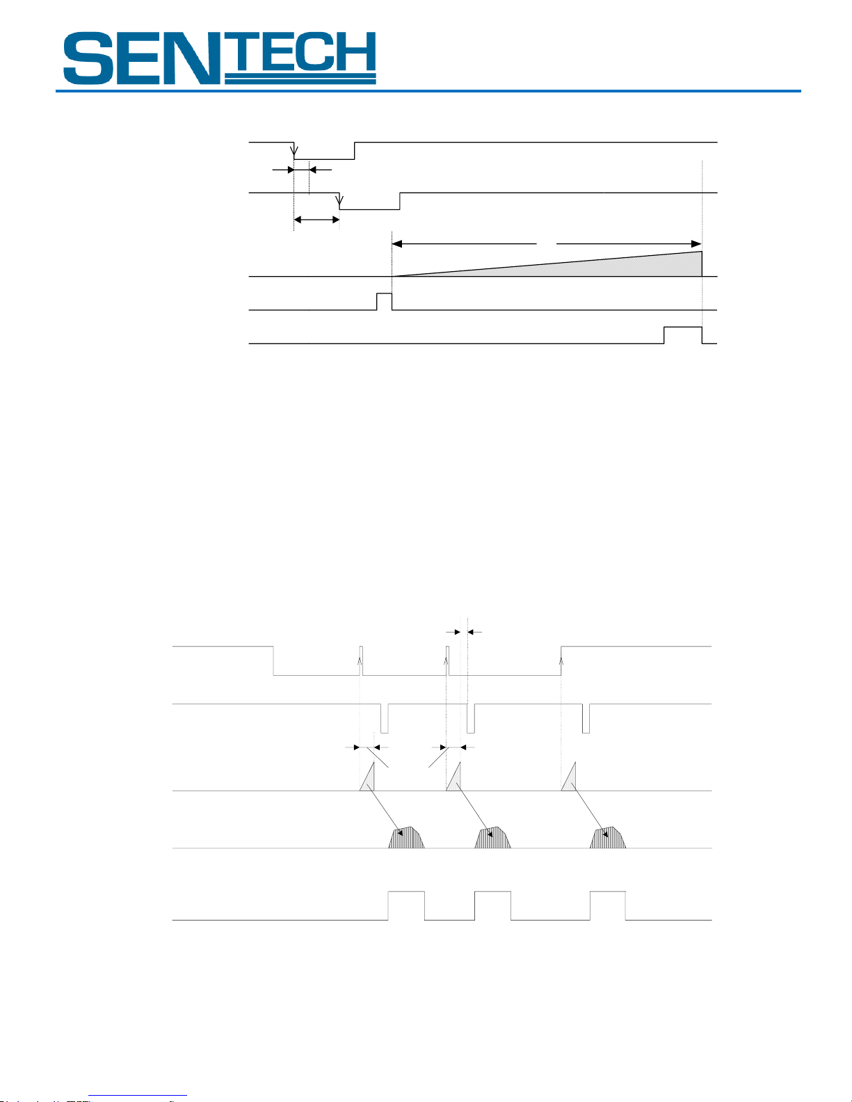
3. Exposure Timing with the Negative Polarity Trigger Signal
Note 1: The trigger signal will be removed by the filtering if the pulse width of the input trigger signal is less than 30 CLK.
Please input a trigger signal with more than 31 CLK pulse width.
Note 2: The exposure will start 110 CLK after the rising edge of the trigger signal.
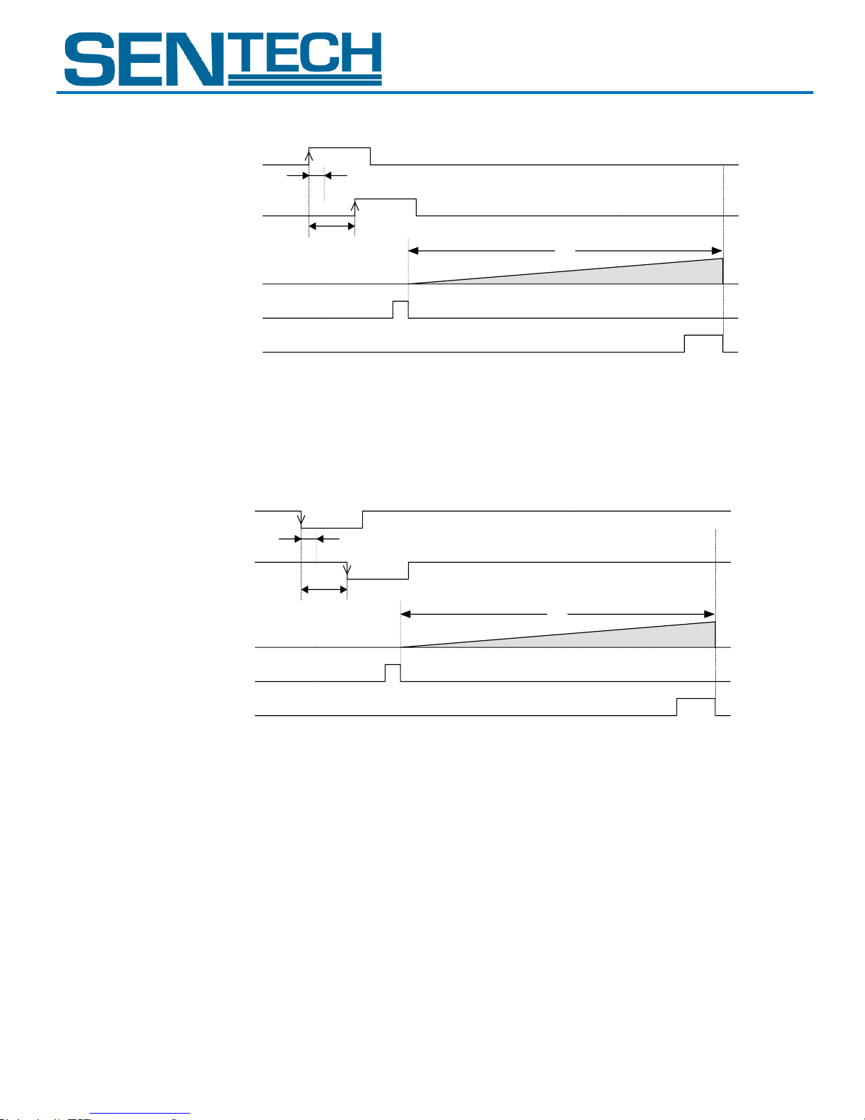
D. Edge Preset Trigger Mode (Trigger input while the image is out)
In this trigger mode, the camera exposure starts at the rising edge of the trigger pulse. The exposure duration time is preset by
the DIP Switch settings.
If trigger signal input is required while the image is out, then it is necessary to disable the trigger signal mask with the
communication.
To avoid generating additional noise on the image, it is necessary to set the “H reset” at the exposure start mode.
1. Timing
User Guide 15 Rev 1.01
Note 1: The video output will be V reset by the next internal HD signal immediately after the exposure is finished.
Note 2: The exposure time is set by the preset electronic shutter speed.
STC-GEC83A
Page 16
STC-GE83A
Input Trigger signal
Exposure time
T1'
SUB
SG
Exposure time: T1' = Preset exposure time
Filtering *Note.1
30CLK
Trigger signal
(With Photocoupler delay)
Less than
5 useconds
Input Trigger signal
Exposure time
T1'
SUB
SG
Exposure time: T1' = Preset exposure time
Filtering *Note.1
30CLK
Trigger signal
(With Photocoupler delay)
Less than
60 useconds
STC-GEC83A
2. Exposure Timing with the Positive Polarity Trigger Signal
Note 1: The trigger signal will be removed by the filtering if the pulse width of the input trigger signal is less than 30 CLK.
Please input a trigger signal with more than 31 CLK pulse width.
Note 2: The exposure will start 110 CLK after the rising edge of the trigger signal.
3. Exposure Timing with the Negative Polarity Trigger Signal
Note 1: The trigger signal will be removed by the filtering if the pulse width of the input trigger signal is less than 30 CLK.
Please input a trigger signal with more than 31 CLK pulse width.
Note 2: The exposure will start 110 CLK after the rising edge of the trigger signal.
User Guide 16 Rev 1.01
Page 17
STC-GE83A
Next HD
Video out
SUB pulse
Internal HD
CCD exposure
Trigger signal
(Rising edge)
Noise
Normal SUB pulse timing
STC-GEC83A
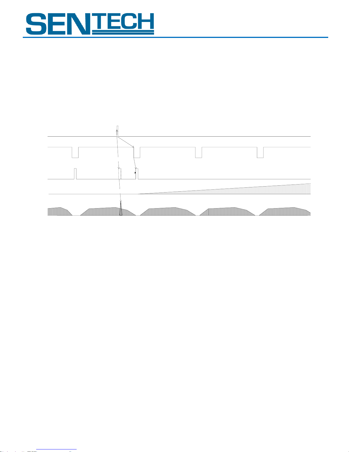
E. H Reset Mode
In this mode, the exposure can be initiated during the video out from the camera without any horizontal noise. A SUB pulse is
generated to sweep the charges during the horizontal blanking period to prevent from getting horizontal noises.
The image will have horizontal noise that is caused by generating the SUB pulse during the video out during normal mode (H
Reset Mode is OFF)
The maximum delay to start exposure from the trigger input is 1H.
User Guide 17 Rev 1.01
Page 18
STC-GE83A
SOF
Device
Code
Read/Write
Page
Selection
Command
Code
Data
Length
Data
EOF
(8bit)
(6bit)
(1bit)
(1bit)
(8bit)
(8bit)
(R: 1 byte)
(W: n bytes)
(8bit)
SOF
Data Length
Data
EOF
(8bit)
(8bit)
(n bytes)
(8bit)
SOF
Data Length
Receiving Code
EOF
(8bit)
(8bit) “00”
(1 byte)
(8bit)
Settings
Baud rate 115,200bps
Data bit 8bit
Parity None
Stop bit 1bit
Flow control None
STC-GEC83A
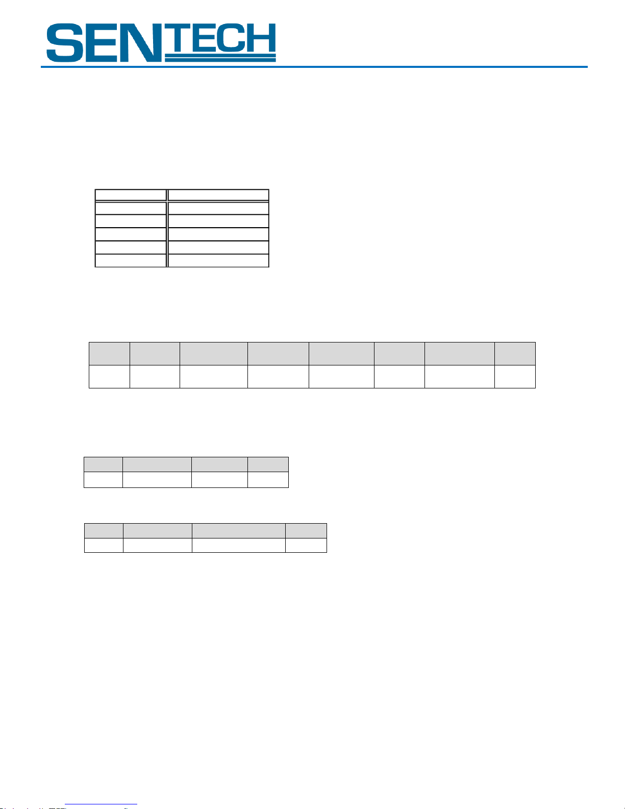
V. The Communication Protocol Specifications
This camera has a communication function that enables external devises, such as a PC, to control the camera’s functions.
Please use the “StCamGigEWare”, “StGigECtrl” communication software, or the following communication protocol to communicate
to the camera:
A. The Communication Method
UART (RS232C), Binary communication
B. The Communication Settings
C. The Communication Format
1. The format for sending data from the PC to the camera is as follows:
a. Sending the Read Command:
2. The format for receiving data from the camera is as follows:
a. After the Read Command is sent:
b. After the Write Command is sent:
User Guide 18 Rev 1.01
Page 19
STC-GE83A
Name
Descriptions
SOF
Start of Frame
Always set (or receive) the value as “02H”
Device Code
Set “000000” when accessing the camera’s function settings
Set “100000” when accessing the camera’s extended function settings.
Please refer to the “Camera Command List” and “Description of the Camera Control Commands”.
Read / Write
Set (or receive) “0” to send the read command.
Set (or receive) “1” to send the write command.
Page Selection
After setting the read or write command, set “0” to access the command register of the camera.
Data is pulled from the command register when the read command is sent.
The existing data of the command register will be replaced by any data sent by the write command.
In this command, the data of the EEPROM is not replaced.
After setting the read or write command, set “1” to access the EEPROM of the camera.
Data is pulled from the EERPOM when the read command is sent.
The existing data of the EEPROM will be replaced by any data sent by the write command.
The receiving code of “01H” is sent by the camera to the PC after the data of the EEPROM is replaced.
Command Code
Please refer to the following page.
Data Length
Data length (unit: byte)
Receiving Data
Receiving data length is dependent on the command that is sent after the read command.
The data length is “00H” after sending the write command.
Sending Data
The data length is 1 byte when sending the read command.
The data length is dependent on the write command that is sent.
Data
The value of the data is dependent of the command.
EOF
End of Frame
Always set or receive the value as “03H”
Receiving Code
This indicates results of the command sent
01H: OK (ACK), 10H: NG (NAC), 12H: Command number error (Not matching),
13H: Communication frame error (only for Gamma data upload),
14H: Time out error (Two seconds),
15H: Check sum error (only for Gamma data upload),
16H: Data length error (Not matching), 17H: EEPROM write error
STC-GEC83A
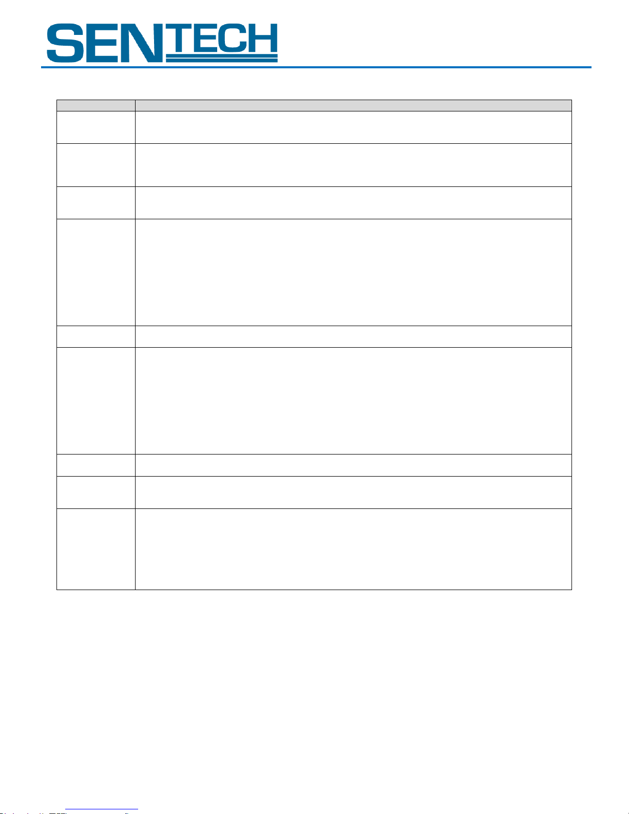
3. Descriptions of the Format
4. Example of Command
Send the read command to read the 00H address data of the register
02, 00, 00, 01, 00, 03
SOF, (Device code/Read/Register), Command code, Data length, Data, EOF
The return command
02, 01, 00, 03
User Guide 19 Rev 1.01
Page 20
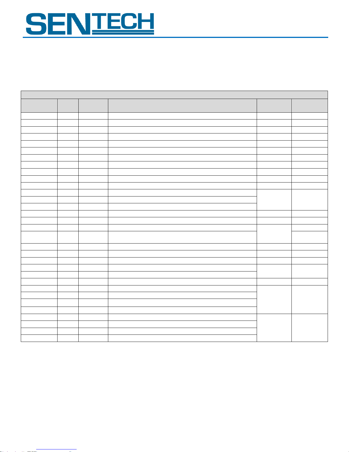
STC-GE83A
Device Code = 000000
Command
No.
R/W
Save to
EEPROM
Function
Initial Data
Data Range
00 to 0FH
Reserved - -
10H
R/W
x
camera function mode 1 (8bit: D[7..0])
89H 11H
R/W
x
camera function mode 2 (8bit: D[7..0])
0FH 12H
R/W
x
camera function mode 3 (8bit: D[7..0])
00H
13H
R/W
x
camera function mode 4 (8bit: D[7..0])
60H
14 to 15H
reserved - -
16H
R/W
x
software trigger mode (8bit: D[7..0])
80H
17H
R/W
x
image data reset (8bit: D[7..0])
00H 18H
reserved - -
19H
R/W
x
image output format (8bit: D[7..0])
01H
1A to 1FH
reserved - -
20H
R/W
x
exposure time (us) of the electronic shutter (24bit: D[7..0])
0
0 to
16,777,215
21H
R/W
x
exposure time (us) of the electronic shutter (24bit: D[15..8])
22H
R/W
x
exposure time (us) of the electronic shutter (24bit: D[24..16])
23 to 2FH
reserved - -
30H
R/W
x
CDS gain (8bit: D[7..0])
0
0 to 255
31H
R/W
x
digital gain (8bit: D[7..0])
factory
adjusted
value
-
32H
R/W
x
gain offset (8bit: D[7..0])
-
33 to 37H
reserved - -
38H
R/W
x
clamp level (8bit: D[7..0])
9
0 to 31
39 to 3DH
reserved - -
3EH
R/W
x
white clip for the test pattern (16bit: D[15..8])
4,095
0 to 4,095
3FH
R/W
x
white clip for the test pattern (16bit: D[7..0])
40 to 4FH
reserved - -
50H
R/W
x
trigger delay time (us) (Integer) (24bit: D[7..0])
0
0 to
2,000,000
51H
R/W
x
trigger delay time (us) (Integer) (24bit: D[15..8])
52H
R/W
x
trigger delay time (us) (Integer) (24bit: D[23..16])
53H
R/W
x
trigger delay time (us) (Decimal) (8bit: D[7..0])
54H
R/W
x
strobe signal delay time (us) (Integer) (24bit: D[7..0])
0
0 to
2,000,000
55H
R/W
x
strobe signal delay time (us) (Integer) (24bit: D[15..8])
56H
R/W
x
strobe signal delay time (us) (Integer) (24bit: D[23..16])
57H
R/W
x
strobe signal delay time (us) (Decimal) (8bit: D[7..0])
STC-GEC83A
D. The Camera Control Commands
1. The Camera Control Commands List
Note 1: The data unit of the each command is 1byte (8bit).
Note 2: The data can be saved to the EEPROM if “x” in the “Save to EEPROM” column on the list below.
The camera is operates with the data of the EEPROM when the camera is powered-on.
User Guide 20 Rev 1.01
Page 21
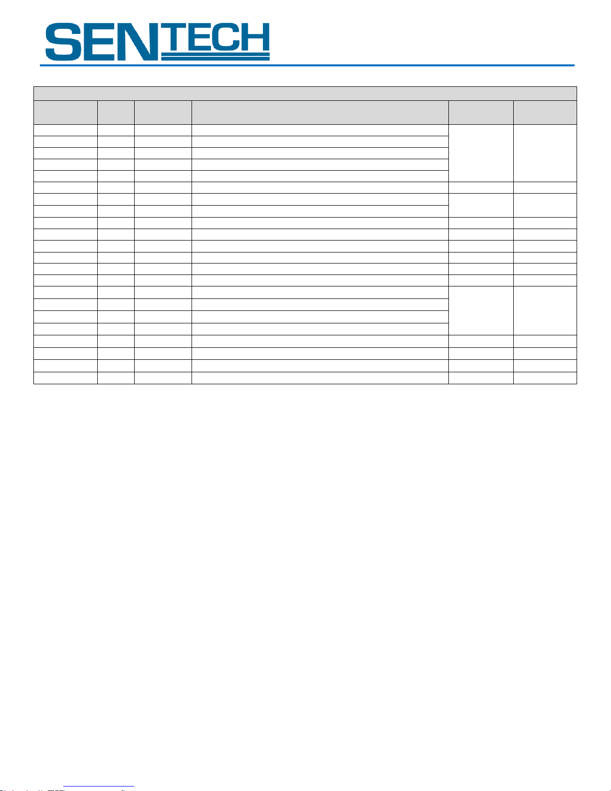
STC-GE83A
Device Code = 000000
Command
No.
R/W
Save to
EEPROM
Function
Initial Data
Data Range
58H
R/W
x
frame rate (Hz) (Integer) (16bit: D[7..0])
36.42113
0.44238 to
150.21358
59H
R/W
x
frame rate (Hz) (Integer) (16bit: D[15..8])
5AH
R/W
x
frame rate (Hz) (Decimal) (24bit: D[7..0])
5BH
R/W
x
frame rate (Hz) (Decimal) (24bit: D[15..8])
5CH
R/W
x
frame rate (Hz) (Decimal) (24bit: D[23..16])
5DH
R/W
x
I/O signal polarity (8bit: D[7..0])
00H
5EF
R/W
x
gain base offset (16bit:D[7..0])
336
0 to 1,023
5FH
R/W
x
gain base offset (16bit:D[15..8])
60 to 77H
reserved - -
78H
R/W
x
test pattern selection (8bit: D[7..0])
00H 79H
R/W
x
image effect selection (8bit: D[7..0])
00H
7A to 7FH
reserved - -
80H
R/W
EEPROM control (8bit: D[7..0])
00H
81 to 8FH
reserved - -
90H
R/W
x
strobe signal active time (us) (Integer) (24bit: D[7..0])
10
0 to
2,000,000
91H
R/W
x
strobe signal active time (us) (Integer) (24bit: D[15..8])
92H
R/W
x
strobe signal active time (us) (Integer) (24bit: D[23..16])
93H
R/W
x
strobe signal active time (us) (Decimal) (8bit: D[7..0])
94 to EFH
reserved
- - F0H
R/W
x
signals of the power-/IO connector (8bit: D[7..0])
20H
F1H
R/W
x
user output signal for the power-I/O connector (8bit: D[7..0])
00H
F2 to FFH
reserved - -
STC-GEC83A
User Guide 21 Rev 1.01
Page 22
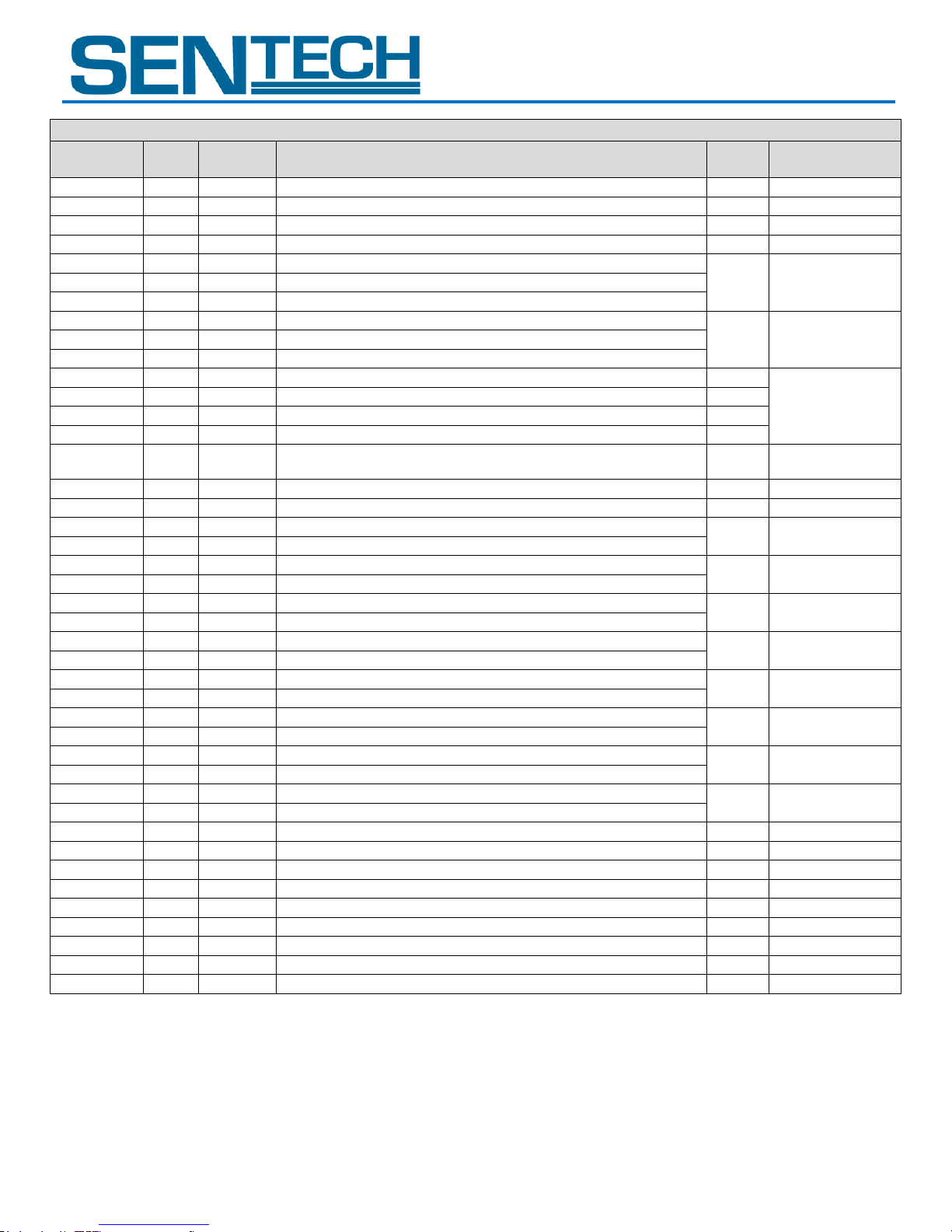
STC-GE83A
Device Code = 100000
Command
No.
R/W
Save to
EEPROM
Function
Initial
Data
Data
Range
00 to 1FH
reserved - -
20H
R/W
x
exposure mode (8bit: D[7..0])
00H 21H
R/W
x
AGC maximum limit (8bit: D[7..0])
255
0 to 255
22H
reserved - -
23H
R/W
x
upper limit of the auto electronic shutter (20bit: D[7..0])
27,458
0 to
16,777,215
24H
R/W
x
upper limit of the auto electronic shutter (20bit: D[15..8])
25H
R/W
x
upper limit of the auto electronic shutter (20bit: D[20..16])
26H
R/W
x
lower limit of the auto electronic shutter (20bit: D[7..0])
1
0 to
16,777,215
27H
R/W
x
lower limit of the auto electronic shutter (20bit: D[15..8])
28H
R/W
x
lower limit of the auto electronic shutter (20bit: D[20..16])
29H
R/W
x
weight1 for ALC (8bit: D[7..0])
11H
D3 to D0: 0 to 15
D7 to D4: 0 to 15
2AH
R/W
x
weight2 for ALC (8bit: D[7..0])
11H
2BH
R/W
x
weight3 for ALC (8bit: D[7..0])
1AH
2CH
R/W
x
weight4 for ALC (8bit: D[7..0])
11H
2DH
R/W
x
weight5 for ALC (8bit: D[7..0])
01H
D3 to D0: 0 to 15
D7 to D4: 0
2EH
R/W
x
target brightness for ALC (8bit: D[7..0])
128
0 to 255
2FH
R/W
x
ALC peak-average (8bit: D[7..0])
0
0 to 255
30H
R/W
x
vertical_1 position for the ALC weight area (16bit: D[7..0])
32
0 to 767
31H
R/W
x
vertical_1 position for the ALC weight area (16bit: D[15..8])
32H
R/W
x
vertical_2 position for the ALC weight area (16bit: D[7..0])
288
0 to 767
33H
R/W
x
vertical_2 position for the ALC weight area (16bit: D[15..8])
34H
R/W
x
vertical_3 position for the ALC weight area (16bit: D[7..0])
480
0 to 767
35H
R/W
x
vertical_3 position for the ALC weight area (16bit: D[15..8])
36H
R/W
x
vertical_4 position for the ALC weight area (16bit: D[7..0])
736
0 to 767
37H
R/W
x
vertical_4 position for the ALC weight area (16bit: D[15..8])
38H
R/W
x
horizontal_1 position for the ALC weight area (16bit: D[7..0])
36
0 to 1,023
39H
R/W
x
horizontal_1 position for the ALC weight area (16bit: D[15..8])
3AH
R/W
x
horizontal_2 position for the ALC weight area (16bit: D[7..0])
377
0 to 1,023
3BH
R/W
x
horizontal_2 position for the ALC weight area (16bit: D[15..8])
3CH
R/W
x
horizontal_3 position for the ALC weight area (16bit: D[7..0])
647
0 to 1,023
3DH
R/W
x
horizontal_3 position for the ALC weight area (16bit: D[15..8])
3EH
R/W
x
horizontal_4 position for the ALC weight area (16bit: D[7..0])
988
0 to 1,023
3FH
R/W
x
horizontal_4 position for the ALC weight area (16bit: D[15..8])
40H
R/W
x
white balance mode (8bit: D[7..0])
00H 41H
R/W
x
preset_1 white balance (Red gain) (8bit: D[7..0])
0
0 to 255
42H
R/W
x
preset_1 white balance (Gr gain) (8bit: D[7..0])
0
0 to 255
43H
R/W
x
preset_1 white balance (Blue gain) (8bit: D[7..0])
0
0 to 255
44H
R/W
x
preset_1 white balance (Gb gain) (8bit: D[7..0])
0
0 to 255
45H
R/W
x
preset_2 white balance (Red gain) (8bit: D[7..0])
0
0 to 255
46H
R/W
x
preset_2 white balance (Gr gain) (8bit: D[7..0])
0
0 to 255
47H
R/W
x
preset_2 white balance (Blue gain) (8bit: D[7..0])
0
0 to 255
48H
R/W
x
preset_2 white balance (Gb gain) (8bit: D[7..0])
0
0 to 255
STC-GEC83A
User Guide 22 Rev 1.01
Page 23
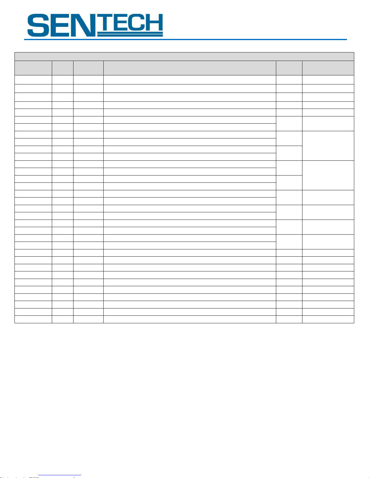
STC-GE83A
Device Code = 100000
Command
No.
R/W
Save to
EEPROM
Function
Initial
Data
Data Range
49H
R/W
x
preset_3 white balance (Red gain) (8bit: D[7..0])
0
0 to 255
4AH
R/W
x
preset_3 white balance (Gr gain) (8bit: D[7..0])
0
0 to 255
4BH
R/W
x
preset_3 white balance (Blue gain) (8bit: D[7..0])
0
0 to 255
4CH
R/W
x
preset_3 white balance (Gb gain) (8bit: D[7..0])
0
0 to 255
4DH
reserved - -
4EH
R/W
x
threshold for auto white balance (16bit: D[7..0])
3,072
0 to 4,095
4FH
R/W
x
threshold for auto white balance (16bit: D[16..8])
50H
R/W
x
Y_offset for AOI (8bit: D[7..0])
0
2 <= Y <= 768,
where Y = offset +
height
51H
R/W
x
Y_offset for AOI (16bit: D[15..8])
52H
R/W
x
height for AOI (8bit: D[7..0])
768
53H
R/W
x
height for AOI (16bit: D[15..8])
54H
R/W
x
X_offset for AOI (8bit: D[7..0])
0
8 <= X <= 1,024,
where X = offset +
width
55H
R/W
x
X_offset for AOI (16bit: D[15..8])
56H
R/W
x
width for AOI (8bit: D[7..0])
1,024
57H
R/W
x
width for AOI (16bit: D[15..8])
58H
R/W
x
vertical_1 position for the white balance area (16bit: D[7..0])
0
0 to 767
59H
R/W
x
vertical_1 position for the white balance area (16bit: D[15..8])
5AH
R/W
x
vertical_2 position for the white balance area (16bit: D[7..0])
767
0 to 767
5BH
R/W
x
vertical_2 position for the white balance area (16bit: D[15..8])
5CH
R/W
x
horizontal_1 position for the white balance area (16bit: D[7..0])
0
0 to 1,023
5DH
R/W
x
horizontal_1 position for the white balance area (16bit: D[15..8])
5EH
R/W
x
horizontal_2 position for the white balance area (16bit: D[7..0])
1,023
0 to 1,023
5FH
R/W
x
horizontal_2 position for the white balance area (16bit: D[15..8])
60H
R/W
x
camera mode1 (8bit: D[7..0])
00H
61 to 7FH
reserved - -
80H
R/W
x
push set white balance (Red gain) (8bit: D[7..0])
0
0 to 255
81H
R/W
x
push set white balance (Gr gain) (8bit: D[7..0])
0
0 to 255
82H
R/W
x
push set white balance (Blue gain) (8bit: D[7..0])
0
0 to 255
83H
R/W
x
push set white balance (Gb gain) (8bit: D[7..0])
0
0 to 255
84 to 90H
reserved - -
91H
reserved - -
92H
R/W
x
iris lens manual adjustment (8bit: D[7..0])
01H 93 to FFH
reserved - -
STC-GEC83A
User Guide 23 Rev 1.01
Page 24
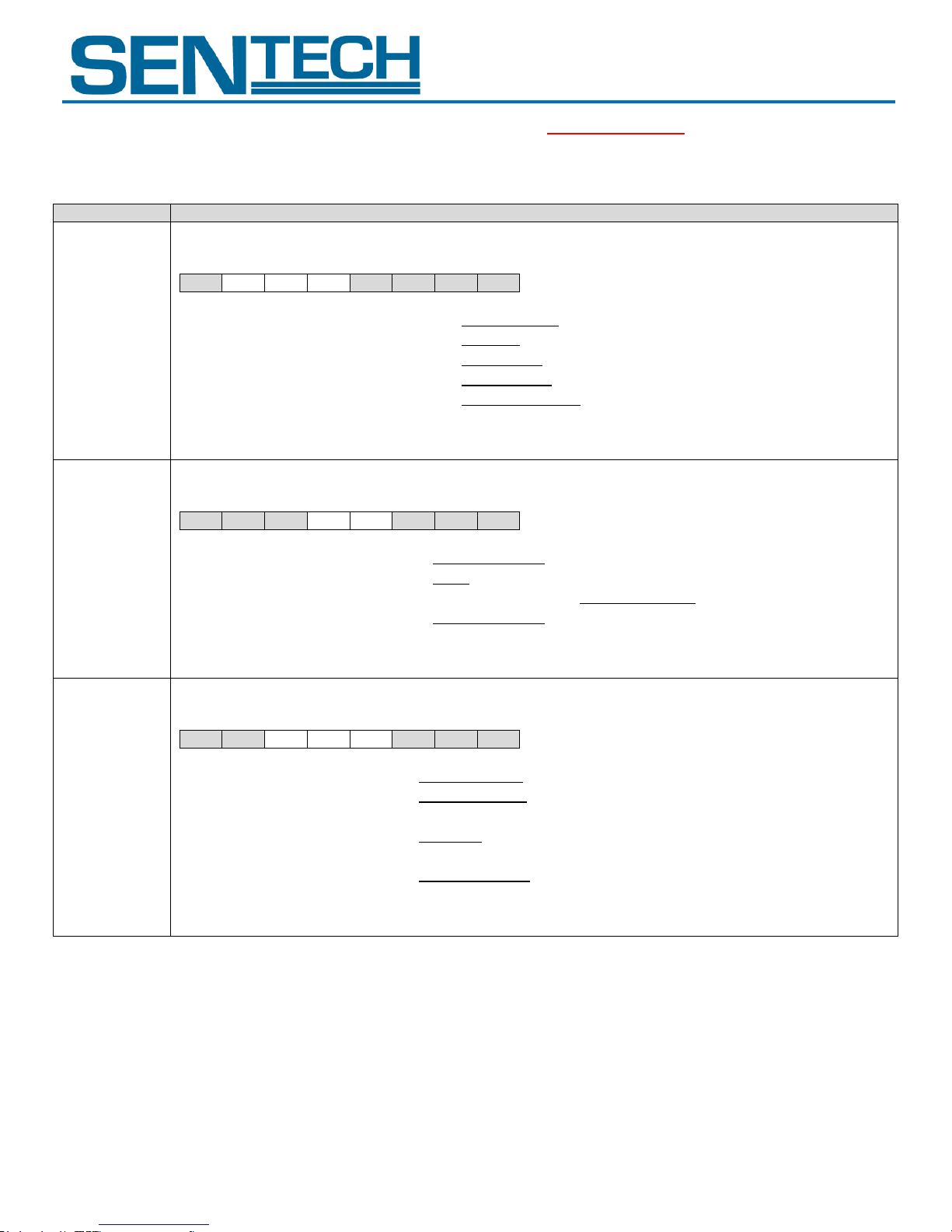
STC-GE83A
Command No.
Command Description
10H:
MOD1[7..0]
[camera function mode 1] Initial data: MOD1[7..0] = 89H
Sets the camera function mode.
D[7..0]
D7
D6
D5
D4
D3
D2
D1
D0
D7:
No Function
Always set as “1”
D6:
Trigger Polarity
0: Positive
1: Negative
D5:
Trigger Mode
0: Edge Preset
1: Pulse Width
D4:
Binning Mode
0: OFF (Normal)
1: ON (Binning)
D3 to D0:
No Function
Always set as “1001”
Note 1: The trigger polarity is automatically set to positive when using the software trigger; the trigger polarity cannot be
changed.
11H:
MOD2[7..0]
[Camera function mode 2] Initial data: MOD2[7..0] = 0FH
Sets the camera function mode.
D[7..0]
D7
D6
D5
D4
D3
D2
D1
D0
D7 to D5:
No Function
Always set as “000”
D4:
Smear Half Reduction
0: OFF
1: ON
D3:
Operational Mode
0: Trigger Mode
1: Continuous Mode
D2 to D0:
No Function
Always set as “111”
Note 1: The function mode is enabled whenever the “Continuous/Trigger mode (MOD1-D7)” is manual.
Note 2: While the camera is in Trigger Mode, the video will not output without the trigger signal input.
12H:
MOD3[7..0]
[Camera function mode 3] Initial data: MOD3[7..0] = 00H
Sets the camera function mode.
D[7..0]
D7
D6
D5
D4
D3
D2
D1
D0
D7 to D6:
No Function
Always set as “00”
D5:
Trigger Signal Type
0: Software Trigger
1: Hardware Trigger
(from No.5 pin of Power-I/O connector)
D4 to D3:
Exposure Start Mode
00: Normal
10 to 11: H Reset
01: No Function (Prohibited setting. Do not set these values)
D2 to D0:
No Function
Always set as “000”
Note 1: The trigger polarity is automatically set to positive when using the software trigger; the trigger polarity cannot be
changed.
STC-GEC83A
2. Description of the camera control commands (Device code: 000000); (The underline settings are the factory default settings)
User Guide 24 Rev 1.01
Page 25
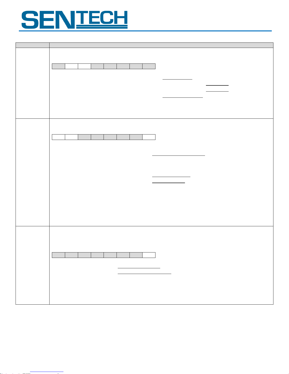
STC-GE83A
Command No.
Command Description
13H:
MOD4[7..0]
[Camera function mode 4] Initial data: MOD4[7..0] = 60H
Sets the camera function mode.
D[7..0]
D7
D6
D5
D4
D3
D2
D1
D0
D7:
No Function
Always set as “0”
D6:
Trigger signal mask during exposure
0: OFF (No mask)
1: ON (Mask)
D5
Trigger signal mask during image output
0: OFF (No mask)
1: ON (Mask)
D4 to D0:
No Function
Always set as “100000”
Note 1: The trigger signal is invalidated when mask function is on.
16H:
SOFTRG[7..0]
[Software Trigger Setting] Initial data: SOFTRG[7..0] = 80H
Sets the source of the software trigger.
D[7..0]
D7
D6
D5
D4
D3
D2
D1
D0
D7 to D6:
Software trigger source selection
00: Programming software trigger
10: Command software trigger
(200 useconds pulse width trigger signal)
01, 11: No function
(Prohibited settings. Do not set these values)
D5 to D1:
No Function
Always set as “00000”
D0:
Generate software trigger command
0: Hold (Low State)
1: Generate command software trigger
(200 useconds high state)
Note 1: The software trigger source selection is enabled whenever “Trigger signal type (MOD3-D5)” is the software
trigger (set as 0)
Note 2: The “Programming software trigger” is used to set up the pulse duration, trigger signal interval and generate the
trigger signal.
Note 3: When selecting “Command software trigger”, it is necessary to generate the software trigger signal with the
“Generate command software trigger (SOFTRIG-D0)”.
17H:
IMAGEREST
[7..0]
[Image Data Reset] Initial data: IMAGEREST[7..0] = 00H
Reset the Image data (FVAL, LVAL and the image data).
Change from the reset to the image data out after starting the image acquisition.
The image data is not output when resetting the image data.
D[7..0]
D7
D6
D5
D4
D3
D2
D1
D0
D7 to D1:
No Function
Always set as “0000000”
D0:
Image Data Reset
0: FVAL/LVAL/Image data reset
(FVAL, LVAL and the image data are low state data)
1: FVAL/LVAL/Image data out
STC-GEC83A
User Guide 25 Rev 1.01
Page 26
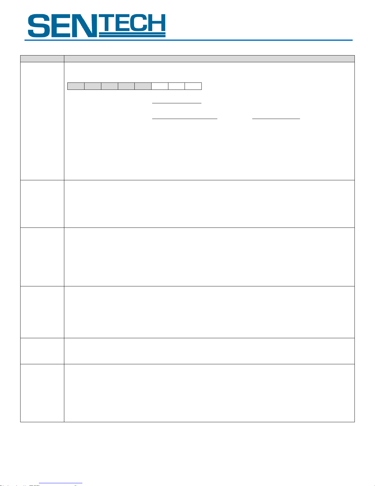
STC-GE83A
Command No.
Command Description
19H
FORMAT[7..0]
[Image output format] initial data: FORMAT[7..0] = 01H
Sets the output format of the image data.
D[7..0]
D7
D6
D5
D4
D3
D2
D1
D0
D7 to D3:
No Function
Always set as “00000”
D2 to D0:
Output format
000: Mono8 (Monochrome)
/ BayerRGB8 (Color)
001: Mono10 (Monochrome)
/ BayerRGB10 (Color)
010: Mono10Packed (Monochrome)
/ BayerRGB12 (Color)
011: Mono12 (Monochrome)
/ BayerRGB10Packed (Color)
100: Mono12Packed (Monochrome)
/ BayerRGB12Packed (Color)
101: No function (Do not set)
/ BayerRGB8Packed (Color)
100 to 111: No function (Prohibited setting. Do not set these values)
20H:
EXPTM[7..0]
21H:
EXPTM[15..8]
22H:
EXPTM[23..16]
[Exposure time (useconds) of the electronic shutter]
Initial data: EXPTM[23..0] = 0, data range: 0 to 16,777,215
Sets the exposure time for the electronic shutter.
Exposure time = EXPTM[23..0] useconds
When set as 0, the electronic shutter is OFF.
30H:
PGA[7..0]
[CDS gain] Initial data: PGA [7..0] = 0, data range: 0 to 255
Sets the CDS gain (programmable gain)
CDS gain = 7.44 + 0.04 x (PGA[7..0] x 2 + GOFS[7..0])dB
*GOFS[7..0]:
The gain offset (The value of the address 32H)
31H:
DGB[7..0]
[Digital gain] Initial data: DGB [7..0] = The factory adjusted value
Video level = (Input video level – CLAMP level) x (1 + DGB[7..0]/128) + CLAMP Level
*CLAMP Level
Clamp level (The calculated value of the address 38H)
32H:
GOFS[7..0]
[Gain offset] Initial data: GOFS[7..0] = The factory adjusted value, data range: 0 to 255
38H:
CLAMP[7..0]
[Clamp level] Initial data: CLAMP[7..0] = 9; data range: 0 to 31
Sets the clamp level (The clamp level of the black signal)
Clamp level = CLAMP[7..0] x 8 + 56
(for 12bit output)
Clamp level = (CLAMP[7..0] x 8 + 56) / 4
(for 10bit output)
Clamp level = (CLAMP[7..0] x 8 + 56) / 16
(for 8 bit output)
Whenever it is set greater than 31, it will automatically resets to 31.
STC-GEC83A
User Guide 26 Rev 1.01
Page 27
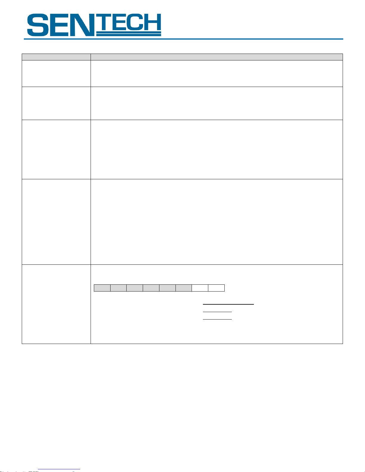
STC-GE83A
Command No.
Command Description
3EH: WHITE_CLIP[15..8]
3FH: WHITE_CLIP[7..0]
[White clip level for the white clip test pattern]
Initial data: WHITE_CLIP[15..0] = 4,095; data range: 0 to 4,095
Sets the white clip level of the white clip test pattern.
50H: DELAY_I[7..0]
51H: DELAY_I[15..8]
52H: DELAY_I[23..16]
53H: DELAY_F[7..0]
[Delay time (us) for the trigger signal]
Initial data: DELAY_I[23..0] = 0, DELAY_F[7..0] = 0, data range: 0 to 2,000,000
Sets the delay time that is from the trigger signal input to the start of the exposure as useconds.
Delay time for the trigger signal = (DELAY_I[23..0]). (DELAY_F[7..0]) useconds
54H:
STROBEDELAY_I[7..0]
55H:
STROBEDELAY_I[15..8]
56H:
STROBEDELAY_I[23..16]
57H:
STROBEDELAY_F[7..0]
[Delay time (us) for the strobe signal]
Initial data: STROBEDELAY _I[23..0] = 0, STROBEDELAY _F[7..0] = 0, data range: 0 to 2,000,000
Delay time for the strobe signal = (STROBEDELAY _I[23..0]). (STROBEDELAY _F[7..0]) useconds
58H: FPS_I[7..0]
59H: FPS_I[15..8]
5AH: FPS_F[7..0]
5BH: FPS_F[15..8]
5CH: FPS_F[23..16]
[Frame rate (Hz)]
Initial data: FPS_I[15..0] = 36, data rage: 0 to 150
Initial data: FPS_F[15..0] = 42,113, data range: 0 to 99,999
Sets the frame rate as Hz
Frame rate = (FPS_I[15..0]). (FPS_F[23..0]) Hz
data range of frame rate: 0.44238 to 150.221358 Hz
Maximum frame rate for full resolution: 36.42113 Hz (as initial data)
Note 1: The maximum frame rate depends on the AOI setting
Note 2: The maximum frame rate is achieved when the vertical resolution is set 1/4 of the full resolution.
The maximum frame rate does not increase even if the vertical resolution is set smaller than 1/4 of the full
resolution.
5DH:
IOSIGNAL_POL[7..0]
[I/O signal polarity] Initial data: IOSIGNAL_POL[7..0] = 00H,
Sets the No.2 pin and No.3 pin of the I/O signal polarity.
D[7..0]
D7
D6
D5
D4
D3
D2
D1
D0
D7 to D2:
No Function
Always set as “000000”
D1
No.3 pin (I/O-2) polarity
0: Non-invert
1: Invert
D0:
No.2 pin (I/O-1) polarity
0: Non-invert
1: Invert
STC-GEC83A
User Guide 27 Rev 1.01
Page 28
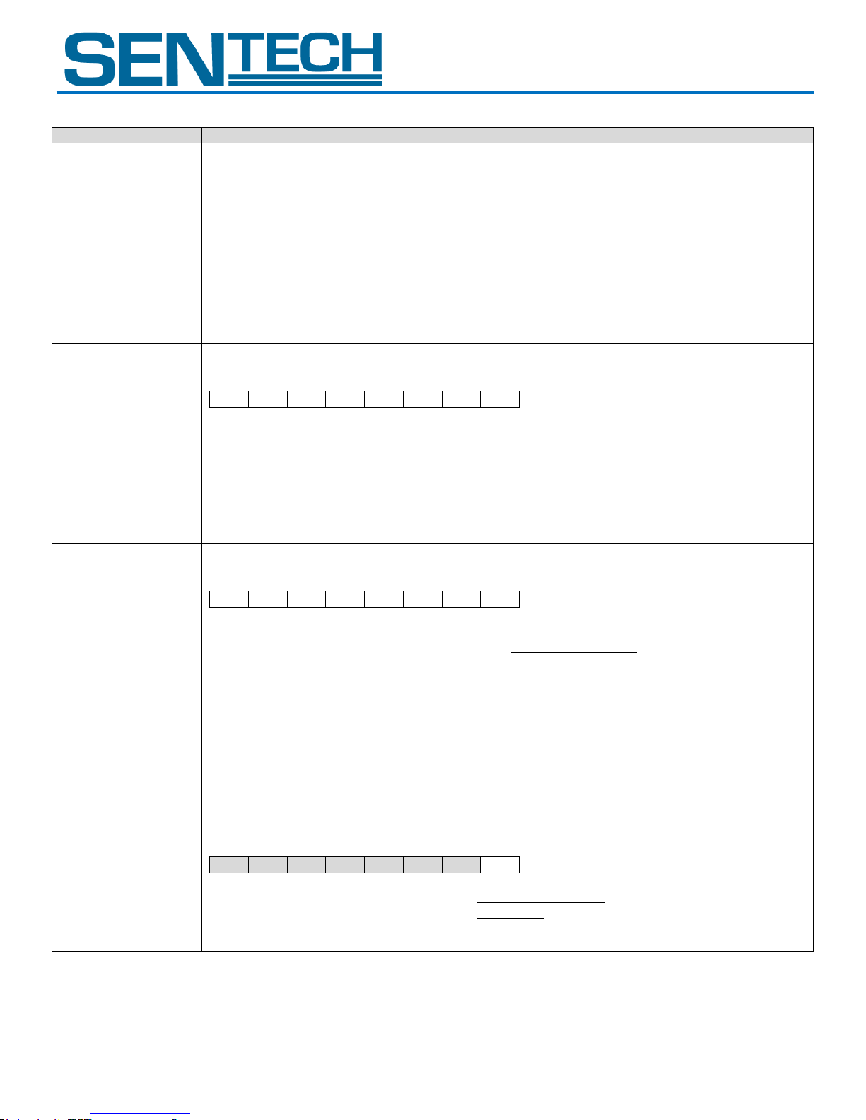
STC-GE83A
Command No.
Command Description
5EH:
CDS_BASEGAIN[7..0]
5FH:
CDS_BASEGAIN[15..8]
[CDS Base Gain] Initial data: CDS_BASEGAIN[15..0] = 336, data range: 0 to 1023
When the result of the below equation exceeds 1023, 1023 will be set
CDS_BASEGAIN[15..0] + PGA[7..0] x 2 + GOFS[7..0]
*PGA[7.0]:
The CDS gain (The value of the address 30H)
*GOFS[7.0]:
The gain offset (The value of the address 32H)
78H: TESTP[7..0]
[Test pattern selection] Initial data: TESTP[7..0] = 00H
Sets the test pattern output from the camera.
D[7..0]
D7
D6
D5
D4
D3
D2
D1
D0 D7 to D0:
00H: Video output
01H: Gray scale
02H: Ramp wave
03H: 100% white
04H: White clip
05H: Color bar (RGB Bayer)
Others: Black
79H:
EFFCT[7..0]
[Image effect selection] Initial data: EFFCT[7..0] = 00H
Sets the image effect.
D[7..0]
D7
D6
D5
D4
D3
D2
D1
D0
D7:
Negative / Positive video selection
0: Positive image
1: Negative image
D6 to D0:
Image effect
00H: No effect (Original)
01H: 9bit gradation
02H: 9bit gradation
03H: 7bit gradation
04H: 6bit gradation
05H: 5bit gradation
06H: 4bit gradation
07H: 3bit gradation
08H: 2bit gradation
09H: 1bit gradation
0A to 7FH: No function
(Prohibited settings. Do not set these values)
80H: E2P[7..0]
[EEPROM control] Initial data: E2P[7..0] = 00H
D[7..0]
D7
D6
D5
D4
D3
D2
D1
D0
D7 to D1:
No function
Always set as “0000000”
D6 to D0:
Write control to the EEPROM
0: Prohibited
1: Accept
Note: This bit is cleared to “0” automatically by the internal processes after the execution of the command.
STC-GEC83A
User Guide 28 Rev 1.01
Page 29
STC-GE83A
Command No.
Command Description
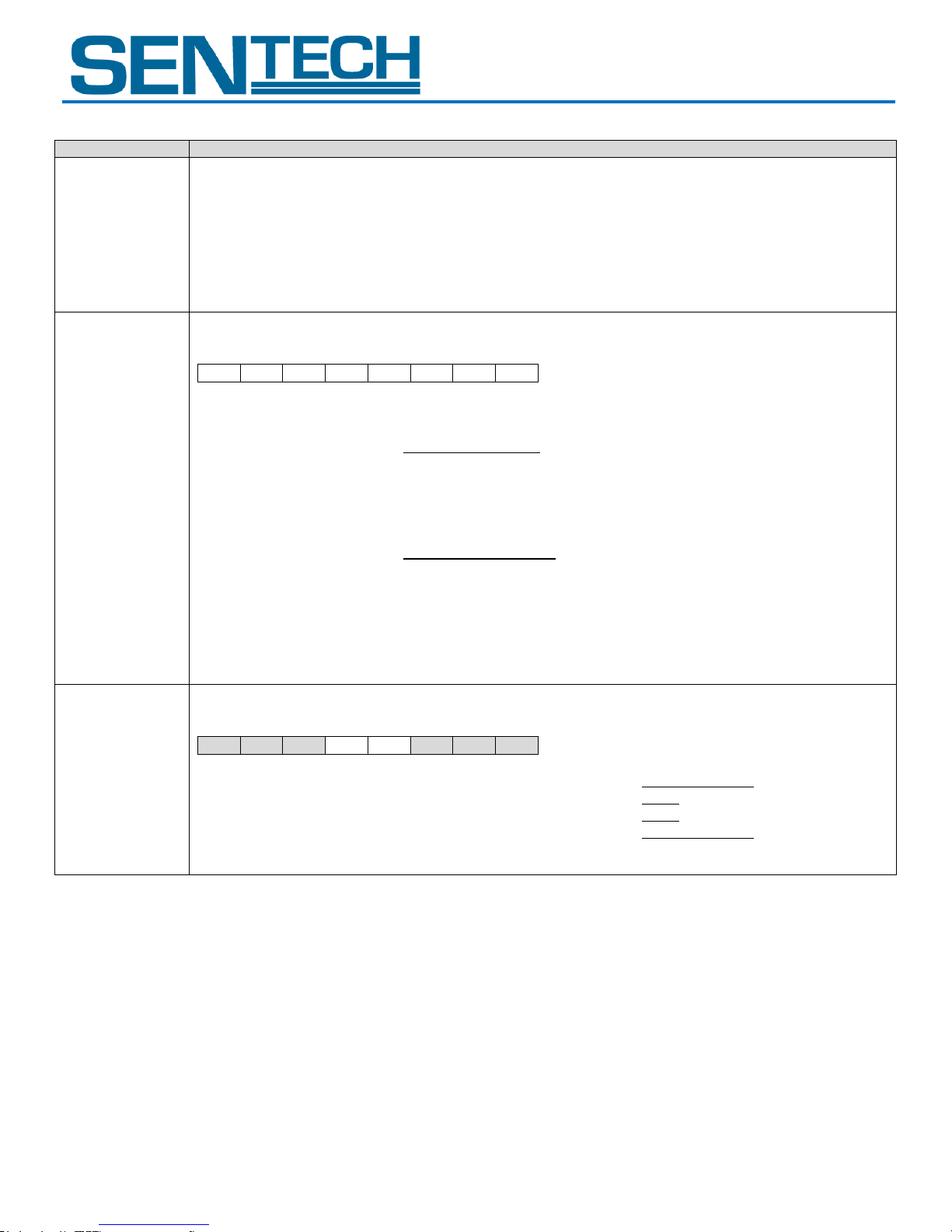
90H:
STROBEON_I[7..0]
91H:
STROBEON_I[15..8]
92H:
STROBEON_I[23..16]
93H:
STROBEON_F[7..0]
[Active time (us) for the strobe signal]
Initial data: STROBEON _I[23..0] =10, STROBEDELAY _F[7..0] = 0, data range: 0 to 2,000,000
Active time for the strobe signal = (STROBEON _I[23..0]). (STROBEON _F[7..0]) useconds
Active time for the strobe signal is set as below.
0: No strobe signal output
1 to 9: 10 us
Greater than 9: set value
F0H:
OUTSEL
[7..0]
[Output signal selection for the power-I/O connector] Initial data: OUTSEL[7..0] = 20H
Sets the output signal from the power/IO connector.
D[7..0]
D7
D6
D5
D4
D3
D2
D1
D0
D7 to D4:
Output signal for 3pin of the power/IO connector
0: FrameTriggerWait signal
1: UserOutput signal
2: ExposureActive signal
3: TriggerAuxiliary signal
4: TriggerInternal signal (after mask and delay process)
5: SensorReadOut signal
6 to F: No Function (Prohibited setting. Do not set these values)
D3 to D0:
Output signal for 2pin of the power/IO connector
0: FrameTriggerWait signal
1: UserOutput signal
2: ExposureActive signal
3: TriggerAuxiliary signal
4: TriggerInternal signal (after mask and delay process)
5: SensorReadOut signal
6 to F: No Function (Prohibited setting. Do not set these values)
Note: When “UserOutput signal” is selected, set the status of the signal with “UserOutput signal for the power/IO
connector (TEST2-D3,4)”.
F1H: TEST2[7..0]
[UserOutput signal for the power-I/O connector] Initial data: TEST2[7..0] = 00H
Sets the status of the UserOutput signal.
D[7..0]
D7
D6
D5
D4
D3
D2
D1
D0
D7 to D5:
No function
Always set as “000”
D4:
UserOutput signal for 3pin of the power/IO connector
0: Low
1: High
D3:
UswerOuput signal for 2pin of the power/IO connector
0: Low
1: High
D2 to D0:
No function
Always set as “000”
Note: The UserOutput signal is enabled whenever “UserOutput signal” is selected at the “Output signal selection
(OUTSEL)”.
STC-GEC83A
User Guide 29 Rev 1.01
Page 30
STC-GE83A
Command No.
Command Description
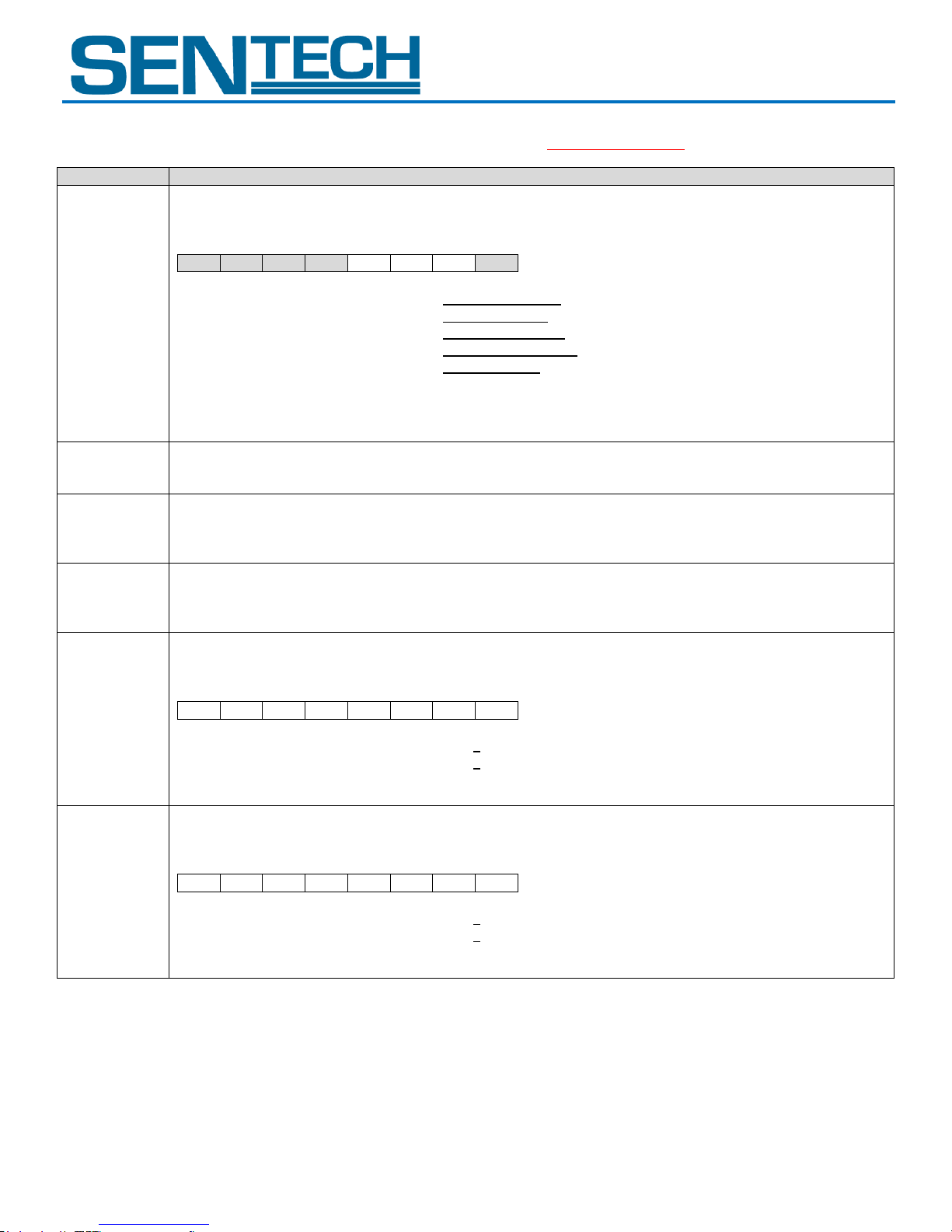
20H: [7..0]
[Exposure mode] Initial data: 00H
Sets the exposure mode, which is the AGC, the shutter mode and the iris lens control method.
D[7..0]
D7
D6
D5
D4
D3
D2
D1
D0
D7 to D4:
No Function
Always set as “0000”
D3:
AGC
0: OFF (Fixed gain)
1: ON (AGC)
D2:
Shutter Mode
0: OFF (Fixed shutter)
1: ON (Auto shutter)
D1:
Iris Lens Control Method
0: OFF (Manual control)
1: ON (Auto control)
D0:
No Function
Always set as “0”
21H: [7..0]
[AGC maximum limit] Initial data: 255, data range: 0 to 255
Sets the maximum limit for the AGC.
23H: [7..0]
24H: [15..8]
25H: [20..16]
[Upper limit of the electronic shutter for auto shutter]
Initial data: 27,458; data range: 0 to 16,777,215
Sets the upper limit of the electronic shutter for the auto shutter as usecond.
26H: [7..0]
27H: [15..8]
28H: [20..16]
[Lower limit of the electronic shutter for auto shutter]
Initial data: 1; data range: 0 to 16,777,215
Sets the upper limit of the electronic shutter for the auto shutter as usecond.
29H: [7..0]
[Weight1 for ALC] Initial data: 11H
Sets the weight for ALC weight area 1 and 2.
D[7..0]
D7
D6
D5
D4
D3
D2
D1
D0 D7 to D4:
Weight for ALC weight area 2
1
Range: 0 to 15
D3 to D0:
Weight for ALC weight area 1
1
Range: 0 to 15
*Please set the ALC weight area with “30H to 3FH”
2AH: [7..0]
[Weight2 for ALC] Initial data: 11H
Sets the weight for ALC weight area 3 and 4.
D[7..0]
D7
D6
D5
D4
D3
D2
D1
D0 D7 to D4:
Weight for ALC weight area 4
1
Range: 0 to 15
D3 to D0:
Weight for ALC weight area 3
1
Range: 0 to 15
*Please set the ALC weight area with “30H to 3FH”
STC-GEC83A
3. Description of the camera control commands (Device code: 100000); (The underline settings are the factory default settings)
User Guide 30 Rev 1.01
Page 31
STC-GE83A
Command No.
Command Description
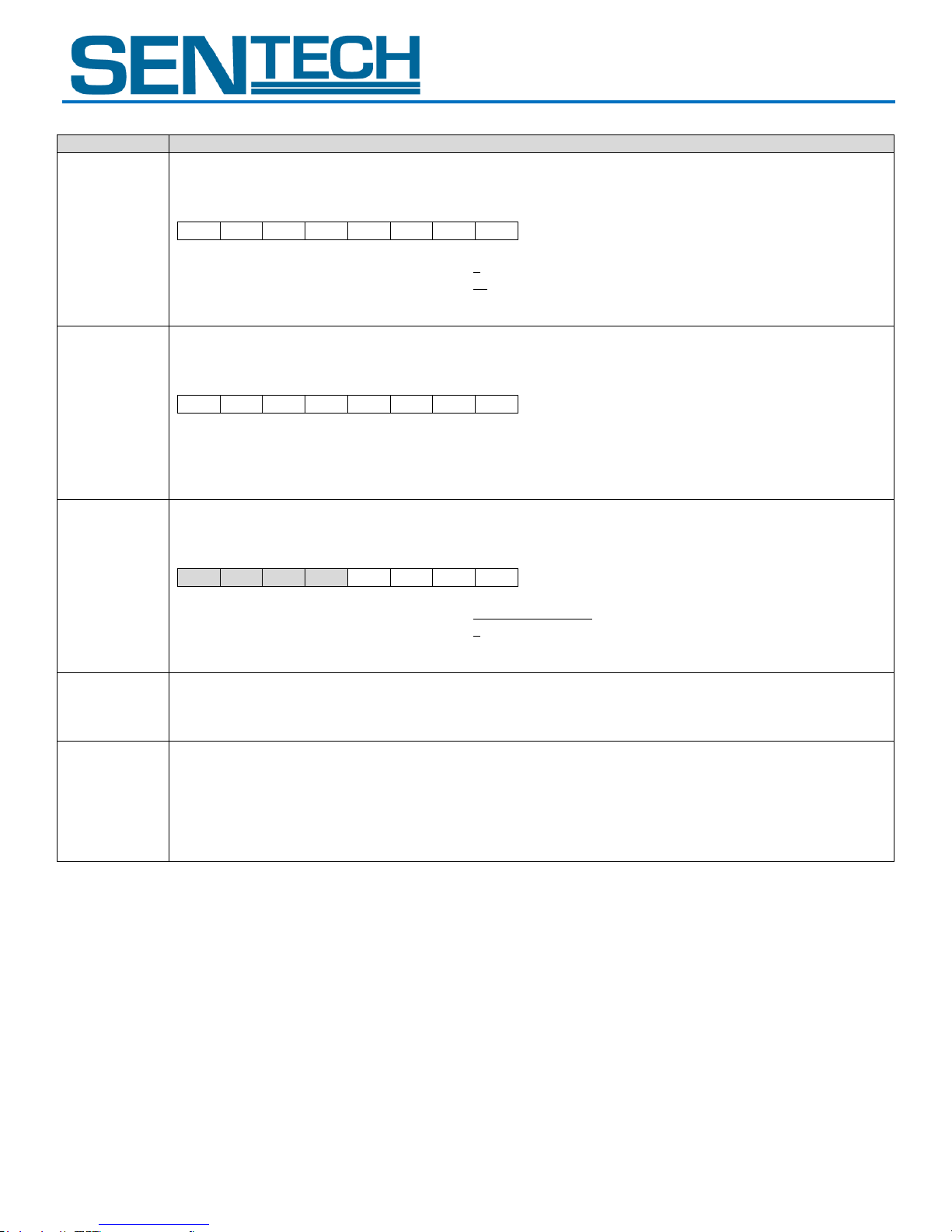
2BH: [7..0]
[Weight3 for ALC] Initial data: 1AH
Sets the weight for ALC weight area 5 and 6.
D[7..0]
D7
D6
D5
D4
D3
D2
D1
D0 D7 to D4:
Weight for ALC weight area 6
1
Range: 0 to 15
D3 to D0:
Weight for ALC weight area 5
10
Range: 0 to 15
*Please set the ALC weight area with “30H to 3FH”
2CH: [7..0]
[Weight4 for ALC] Initial data: 11H
Sets the weight for ALC weight area 7 and 8.
D[7..0]
D7
D6
D5
D4
D3
D2
D1
D0 D7 to D4:
Weight for ALC weight area 8
1
Range: 0 to 15
D3 to D0:
Weight for ALC weight area 7
1
Range: 0 to 15
*Please set the ALC weight area with “30H to 3FH”
2DH: [7..0]
[Weight5 for ALC] Initial data: 01H
Sets the weight for ALC weight area 9.
D[7..0]
D7
D6
D5
D4
D3
D2
D1
D0
D7 to D4:
No Function
Always set as “0000”
D3 to D0:
Weight for ALC weight area 9
1
Range: 0 to 15
*Please set the ALC weight area with “30H to 3FH”
2EH: [7..0]
[Target Brightness for ALC] Initial data: 128, data range: 0 to 255
Sets the target brightness for the ALC function (AGC, auto shutter or iris lens auto control).
2FH: [7..0]
[ALC peak-average] Initial data: 0, data range: 0 to 255
Sets the control standard for the ALC function (AGC, auto shutter or iris lens auto control)
When set as 0 (Average: 100%, Peak: 0%), the ALC function with the average brightness of the photometry area.
When set as 255 (Average: 0%, Peak: 100%), the ALC function with the peak brightness of the photometry area.
STC-GEC83A
User Guide 31 Rev 1.01
Page 32
STC-GE83A
Command No.
Command Description
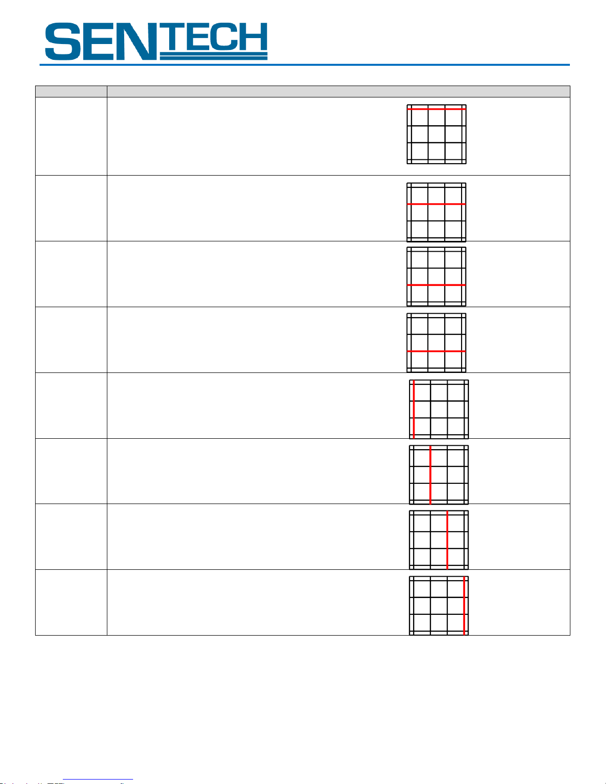
30H: [7..0]
31H: [15..8]
[Vertical_1 position for the ALC weight area]
Initial data: 32, data range: 0 to767
Sets the vertical 1 position for the ALC weight area.
32H: [7..0]
33H: [15..8]
[Vertical_2 position for the ALC weight area]
Initial data: 288, data range: 0 to 767
Sets the vertical 2 position for the ALC weight area.
34H: [7..0]
35H: [15..8]
[Vertical_3 position for the ALC weight area]
Initial data: 480, data range: 0 to 767
Sets the vertical 3 position for the ALC weight area.
36H: [7..0]
37H: [15..8]
[Vertical_4 position for the ALC weight area]
Initial data: 736, data range: 0 to 767
Sets the vertical 4 position for the ALC weight area.
38H: [7..0]
39H: [15..8]
[Horizontal_1 position for the ALC weight area]
Initial data: 36, data range: 0 to 1,023
Sets the horizontal 1 position for the ALC weight area.
3AH: [7..0]
3BH: [15..8]
[Horizontal_2 position for the ALC weight area]
Initial data: 377, data range: 0 to1,023
Sets the horizontal 2 position for the ALC weight area.
3CH: [7..0]
3DH: [15..8]
[Vertical_3 position for the ALC weight area]
Initial data: 647, data range: 0 to 1,023
Sets the horizontal 3 position for the ALC weight area.
3EH: [7..0]
3FH: [15..8]
[Vertical_4 position for the ALC weight area]
Initial data:988, data range: 0 to 1,023
Sets the horizontal 4 position for the ALC weight area.
3
6
9
2
5
8
1
4
7
3
6
9
2
5
8
1
4
7
3
6
9
2
5
8
1
4
7
3
6
9
2
5
8
1
4
7
3
6
9
2
5
8
1
4
7
3
6
9
2
5
8
1
4
7
3
6
9
2
5
8
1
4
7
3
6
9
2
5
8
1
4
7
STC-GEC83A
User Guide 32 Rev 1.01
Page 33
STC-GE83A
Command No.
Command Description
40H: [7..0]
[White Balance mode] Initial data: 00H
Sets the white balance mode for the color camera.
D[7..0]
D7
D6
D5
D4
D3
D2
D1
D0 D7 to D4:
No Function
Always set as “0000”
D3:
Push to set white balance operation
0: OFF
1: ON
D2 to D0:
White balance mode
000: OFF
001: Preset 1,
010: Preset 2
011: Preset 3
100: Auto white balance
101: Push to set white balance
110 to 111: No Function
(Prohibited settings. Do not set these values)
* When using the push-to-set white balance, set the white balance mode as “Push to set white balance” then change “0” to
“1” for the push-to-set white balance operation.
41H:
GainR1[7..0]
[Preset_1 white balance (Red gain)] Initial data: 0, data range: 0 to 255
Sets the Red gain for the preset_1 white balance.
Red of the camera output image data = (CCD_R – CLAMP Level) x (1+ GainR1[7..0] / 64) + CLAMP Level
* CCD_R: Red of the CCD output image data
* CLAMP Level: Clamp level (The calculated value of 38H)
42H:
GainGr1[7..0]
[Preset_1 white balance (Gr gain)] Initial data: 0, data range: 0 to 255
Sets the Gr gain for the preset_1 white balance.
Gr of the camera output image data = (CCD_Gr – CLAMP Level) x (1+ GainGr1[7..0] / 64) + CLAMP Level
* CCD_Gr: Red of the CCD output image data
* CLAMP Level: Clamp level (The calculated value of 38H)
43H:
GainB1[7..0]
[Preset_1 white balance (Blue gain)] Initial data: 0, data range: 0 to 255
Sets the Blue gain for the preset_1 white balance.
Blue of the camera output image data = (CCD_B – CLAMP Level) x (1+ GainB1[7..0] / 64) + CLAMP Level
* CCD_B: Blue of the CCD output image data
* CLAMP Level: Clamp level (The calculated value of 38H)
44H:
GainGb1[7..0]
[Preset_1 white balance (Gb gain)] Initial data: 0, data range: 0 to 255
Sets the Gb gain for the preset_1 white balance.
Gb of the camera output image data = (CCD_Gb – CLAMP Level) x (1+ GainGb1[7..0] / 64) + CLAMP Level
* CCD_Gb: Gb of the CCD output image data
* CLAMP Level: Clamp level (The calculated value of 38H)
STC-GEC83A
User Guide 33 Rev 1.01
Page 34
STC-GE83A
Command No.
Command Description
45H:
GainR2[7..0]
[Preset_2 white balance (Red gain)] Initial data: 0, data range: 0 to 255
Sets the Red gain for the preset_1 white balance.
Red of the camera output image data = (CCD_R – CLAMP Level) x (1+ GainR2[7..0] / 64) + CLAMP Level
* CCD_R: Red of the CCD output image data
* CLAMP Level: Clamp level (The calculated value of 38H)
46H:
GainGr2[7..0]
[Preset_2 white balance (Gr gain)] Initial data: 0, data range: 0 to 255
Sets the Gr gain for the preset_2 white balance.
Gr of the camera output image data = (CCD_Gr – CLAMP Level) x (1+ GainGr2[7..0] / 64) + CLAMP Level
* CCD_Gr: Red of the CCD output image data
* CLAMP Level: Clamp level (The calculated value of 38H)
47H:
GainB2[7..0]
[Preset_2 white balance (Blue gain)] Initial data: 0, data range: 0 to 255
Sets the Blue gain for the preset_2 white balance.
Blue of the camera output image data = (CCD_B – CLAMP Level) x (1+ GainB2[7..0] / 64) + CLAMP Level
* CCD_B: Blue of the CCD output image data
* CLAMP Level: Clamp level (The calculated value of 38H)
48H:
GainGb2[7..0]
[Preset_2 white balance (Gb gain)] Initial data: 0, data range: 0 to 255
Sets the Gb gain for the preset_2 white balance.
Gb of the camera output image data = (CCD_Gb – CLAMP Level) x (1+ GainGb2[7..0] / 64) + CLAMP Level
* CCD_Gb: Gb of the CCD output image data
* CLAMP Level: Clamp level (The calculated value of 38H)
49H:
GainR3[7..0]
[Preset_3 white balance (Red gain)] Initial data: 0, data range: 0 to 255
Sets the Red gain for the preset_3 white balance.
Red of the camera output image data = (CCD_R – CLAMP Level) x (1+ GainR3[7..0] / 64) + CLAMP Level
* CCD_R: Red of the CCD output image data
* CLAMP Level: Clamp level (The calculated value of 38H)
4AH:
GainGr3[7..0]
[Preset_3 white balance (Gr gain)] Initial data: 0, data range: 0 to 255
Sets the Gr gain for the preset_3 white balance.
Gr of the camera output image data = (CCD_Gr – CLAMP Level) x (1+ GainGr3[7..0] / 64) + CLAMP Level
* CCD_Gr: Red of the CCD output image data
* CLAMP Level: Clamp level (The calculated value of 38H)
STC-GEC83A
User Guide 34 Rev 1.01
Page 35
STC-GE83A
Command No.
Command Description
4BH:
GainB3[7..0]
[Preset_3 white balance (Blue gain)] Initial data: 0, data range: 0 to 255
Sets the Blue gain for the preset_3 white balance.
Blue of the camera output image data = (CCD_B – CLAMP Level) x (1+ GainB3[7..0] / 64) + CLAMP Level
* CCD_B: Blue of the CCD output image data
* CLAMP Level: Clamp level (The calculated value of 38H)
4CH:
GainGb3[7..0]
[Preset_3 white balance (Gb gain)] Initial data: 0, data range: 0 to 255
Sets the Gb gain for the preset_3 white balance.
Gb of the camera output image data = (CCD_Gb – CLAMP Level) x (1+ GainGb3[7..0] / 64) + CLAMP Level
* CCD_Gb: Gb of the CCD output image data
* CLAMP Level: Clamp level (The calculated value of 38H)
4EH: [7..0]
4FH: [15..8]
[Bright level threshold fro auto white balance process] Initial data: 3,072, data range: 0 to 4,095
Sets the bright level threshold for auto white balance process.
Auto white balance process uses the color information of the pixel (the brightness of the pixel that is greater than this
value).
50H: [7..0]
51H: [15..8]
[Y_offset for AOI]
Initial data: 0, data range: 2 ≤ “Y_offset + Height” ≤ 768
Sets the Y_offset (the vertical start position of the image for the AOI)
52H: [7..0]
53H: [15..8]
[Height for AOI]
Initial data: 768, data range: 2 ≤ “Y_offset + Height” ≤ 768
Sets the height (the vertical size of the image for the AOI)
54H: [7..0]
55H: [15..8]
[X_offset for AOI]
Initial data: 0, data range: 8 ≤ “Y_offset + Height” ≤ 1,024
Sets the X_offset (the horizontal start position of the image for the AOI)
56H: [7..0]
57H: [15..8]
[Width for AOI]
Initial data: 1,024, data range: 8 ≤ “Y_offset + Height” ≤ 1,024
Sets the width (the horizontal size of the image for the AOI)
58H: [7..0]
59H: [15..8]
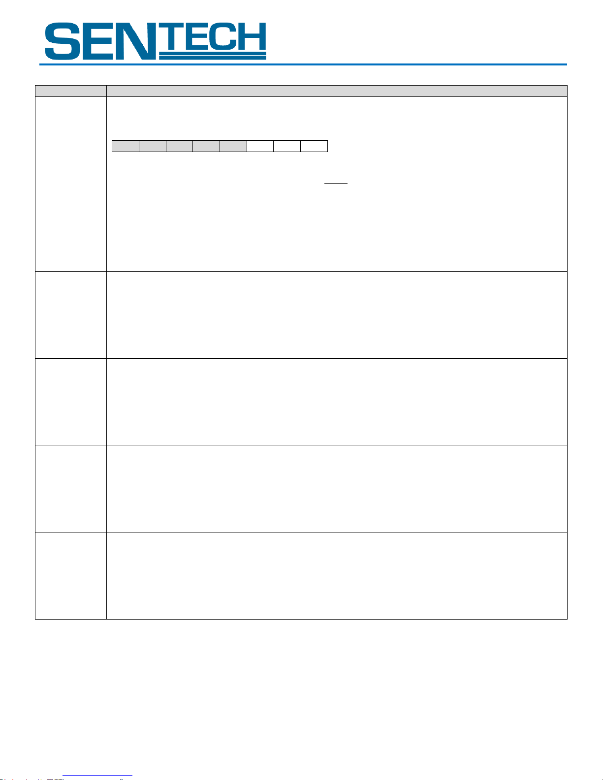
[Vertical_1 position for the white balance area]
Initial data: 0, data range: 0 to 767
Sets the vertical 1 position, which is the vertical start position for the white blance area.
This area is used for the gain calculation of the auto white balance and the push-to-set white balance.
STC-GEC83A
User Guide 35 Rev 1.01
Page 36
STC-GE83A
Command No.
Command Description
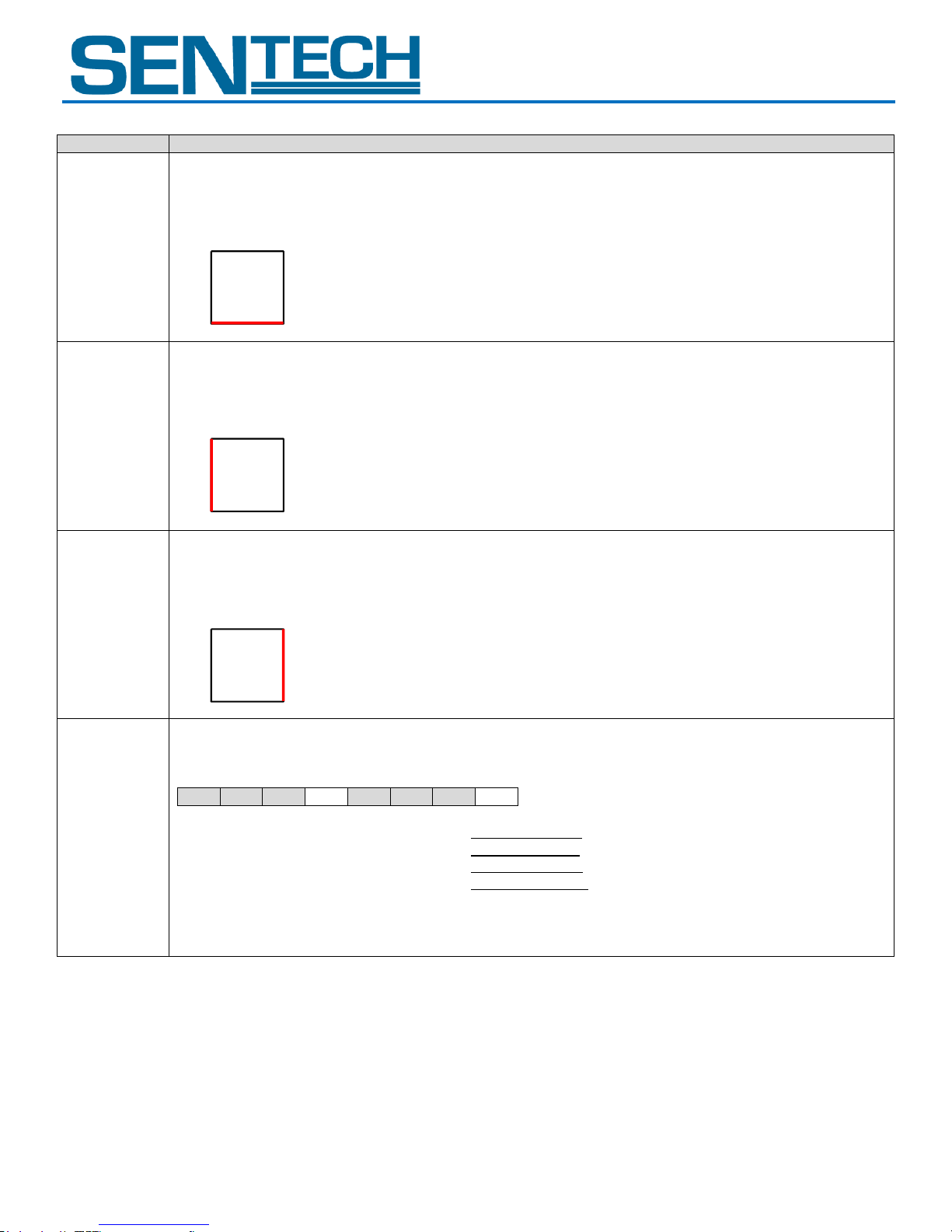
5AH: [7..0]
5BH: [15..8]
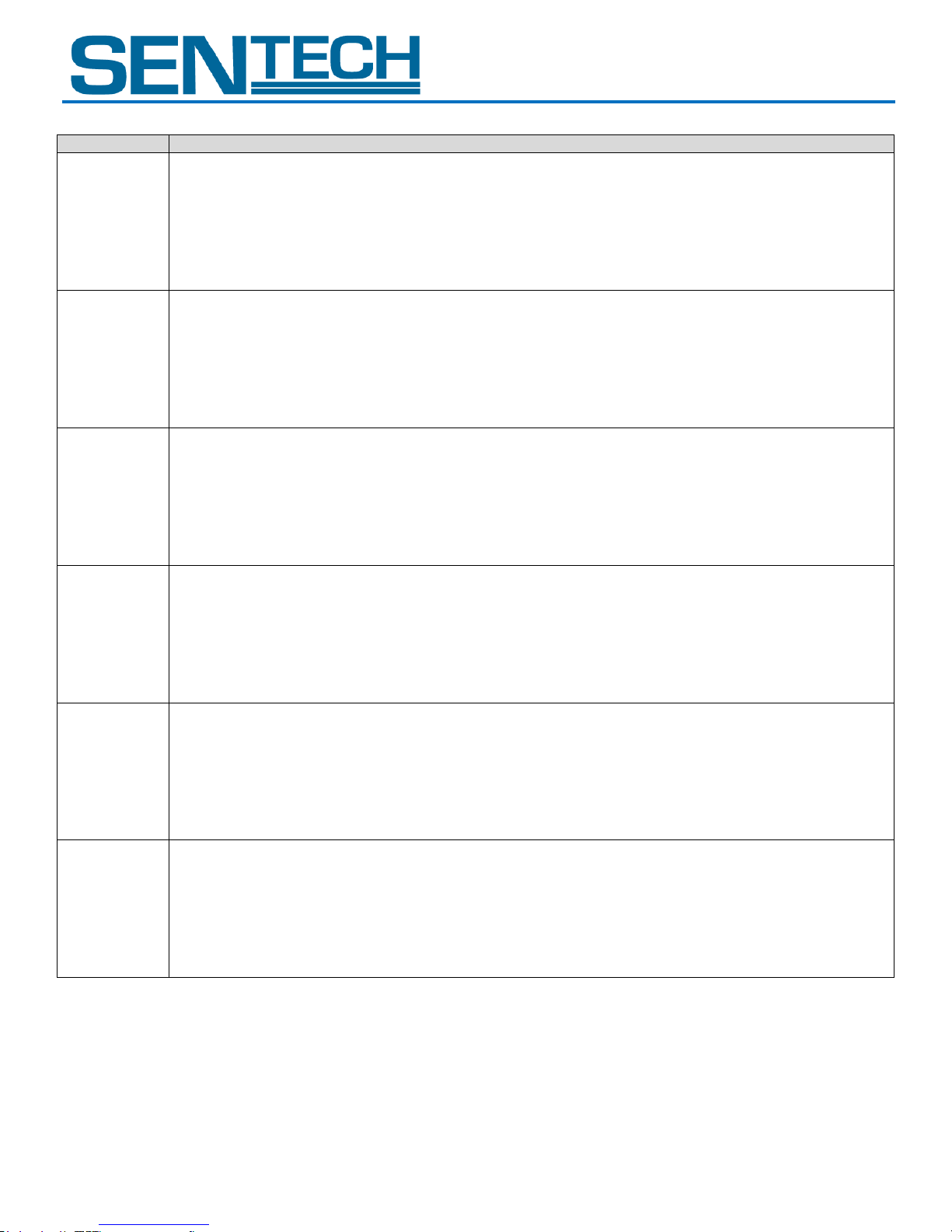
[Vertical_2 position for the white balance area]
Initial data: 767, data range: 0 to 767
Sets the vertical 2 position, which is the vertical end position for the white blance area.
This area is used for calculating the gain of the auto white balance and the push-to-set white balance.
5CH: [7..0]
5DH: [15..8]
[Horizontal_1 position for the white balance area]
Initial data: 0, data range: 0 to 1,023
Sets the horizontal 1 position, which is the vertical end position for the white blance area.
This area is used for calculating the gain of the auto white balance and the push-to-set white balance.
5EH: [7..0]
5FH: [15..8]
[Horizontal_2 position for the white balance area]
Initial data: 1,023, data range: 0 to 1,023
Sets the horizontal 2 position, which is the vertical end position for the white blance area.
This area is used for the calculating the gain of the auto white balance and the push-to-set white balance.
60H: [7..0]
[Camera mode 1] Initial data: 00H
Sets the white balance area ON/OFF and the gamma table ON/OFF.
D[7..0]
D7
D6
D5
D4
D3
D2
D1
D0
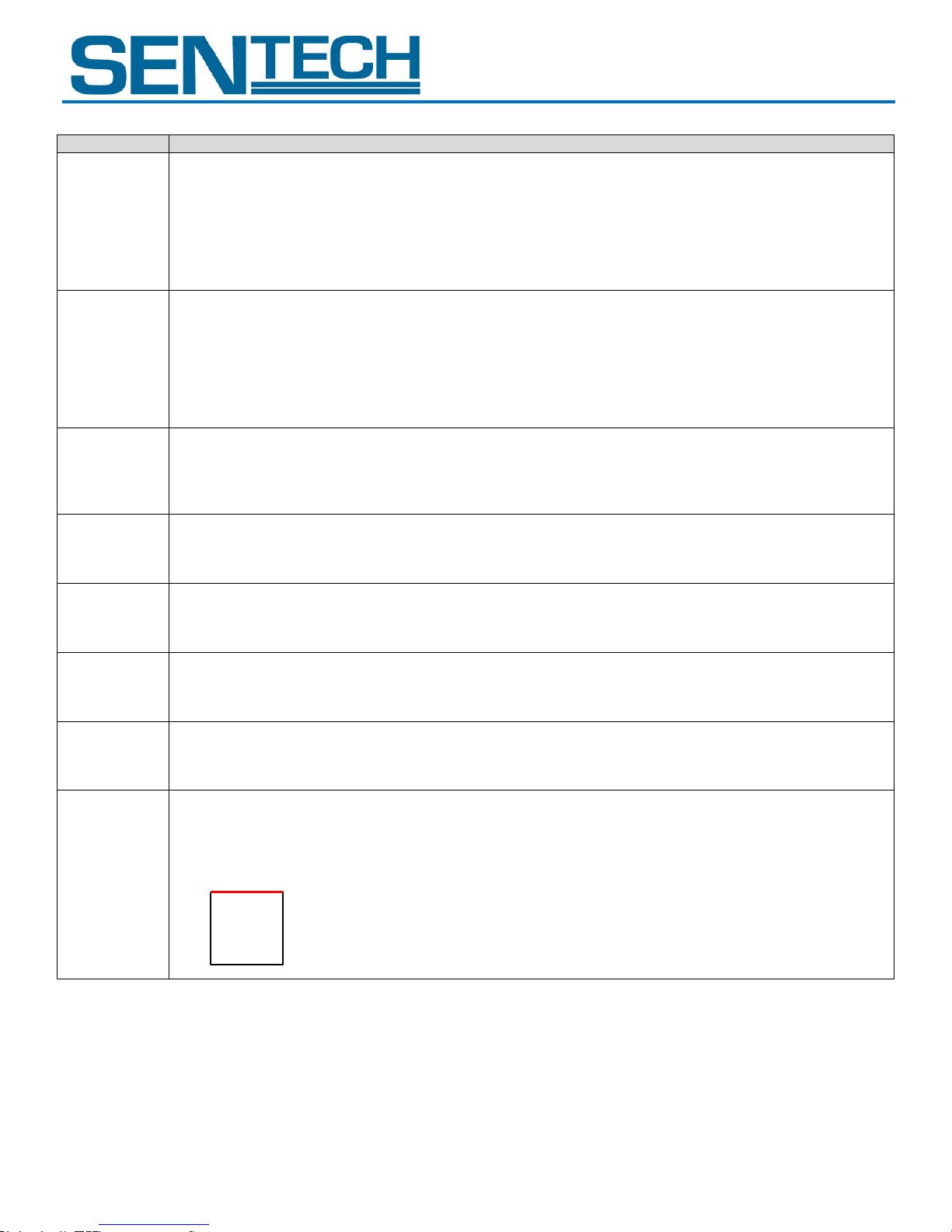
D7 to D5:
No function
Always set at “000”
D4:
White balance area ON/OFF
0: OFF (Full screen)
1: ON (setup area)
D3 to D1:
No function
Always set as “000”
D0:
Gamma table ON/OFF
0: OFF (Gamma=1.0)
1: ON
STC-GEC83A
User Guide 36 Rev 1.01
Page 37
STC-GE83A
Command No.
Command Description
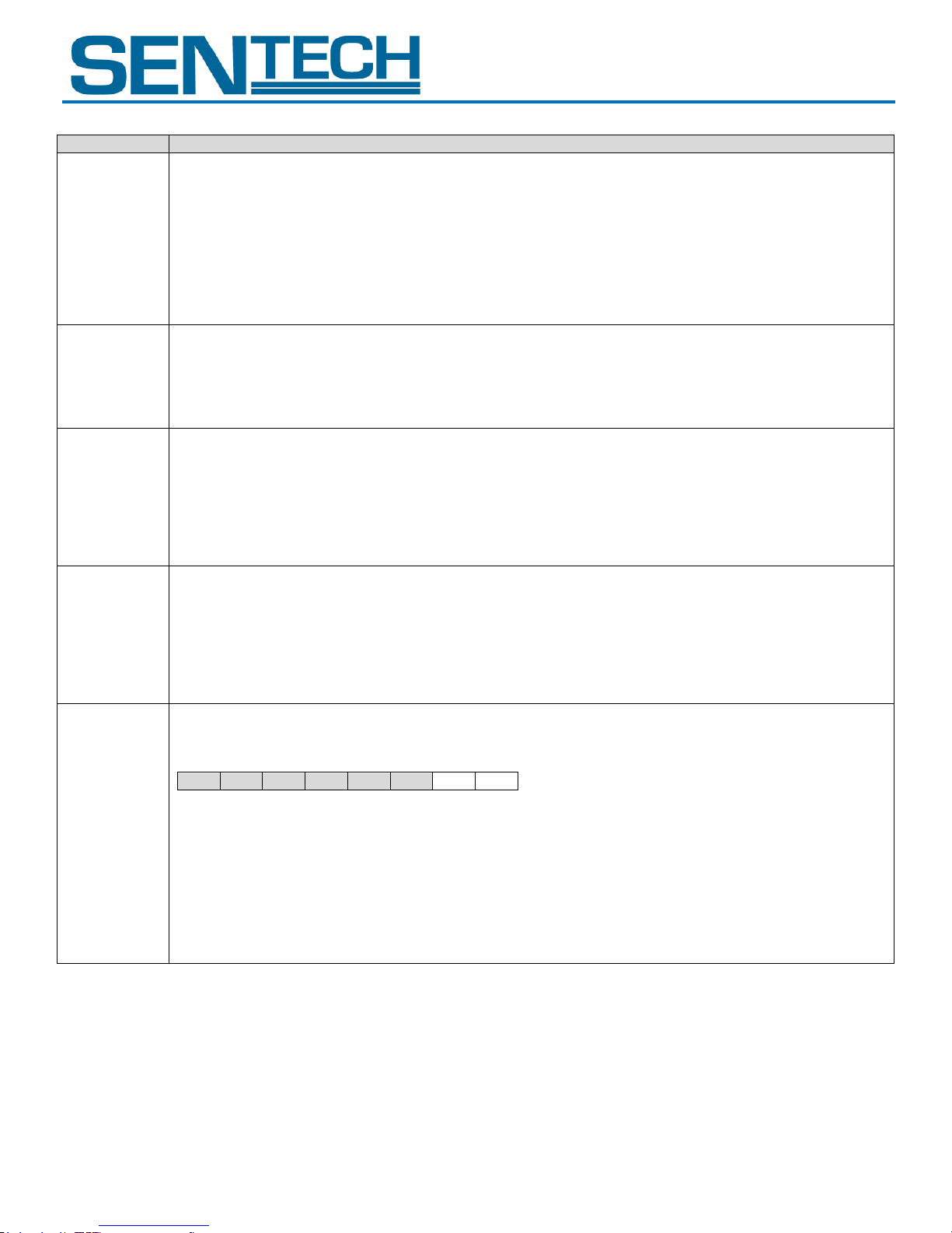
80H:
GainRP[7..0]
[Push to set white balance (Red gain)] Initial data: 0, data range: 0 to 255
Sets the Red gain for the Push to set white blance.
Red of the camera ouptut image data = (CCD_R – CLAMP Level) x (1 + GainRP[7..0] / 64) + CLAMP Level
*CCD_R: Red of the CCD output image data
*CLAMP Level: Clamp level (The calculated value of 38H)
*CCD_Gr: Gr of the CCD output image data
*CLAMP Level: Clamp level (The calculated value of 38H)
81H:
GainGrP[7..0]
[Push to set white balance (Gr gain)] Initial data: 0, data range: 0 to 255
Sets the Gr gain for the Push to set white blance.
Gr of the camera ouptut image data = (CCD_Gr – CLAMP Level) x (1 + GainGrP[7..0] / 64) + CLAMP Level
82H:
GainBR[7..0]
[Push to set white balance (Blue gain)] Initial data: 0, data range: 0 to 255
Sets the Blue gain for the Push to set white blance.
Red of the camera ouptut image data = (CCD_B – CLAMP Level) x (1 + GainBR[7..0] / 64) + CLAMP Level
*CCD_B: Blue of the CCD output image data
*CLAMP Level: Clamp level (The calculated value of 38H)
83H:
GainGbP[7..0]
[Push to set white balance (Gb gain)] Initial data: 0, data range: 0 to 255
Sets the Gb gain for the Push to set white blance.
Gb of the camera ouptut image data = (CCD_Gb – CLAMP Level) x (1 + GainGbP[7..0] / 64) + CLAMP Level
*CCD_Gb: Gb of the CCD output image data
*CLAMP Level: Clamp level (The calculated value of 38H)
92H: [7..0]
[Iris lens manual adjustment] Initial data: 01H
Sets the iris lens manual adjustment operation.
D[7..0]
D7
D6
D5
D4
D3
D2
D1
D0 D7 to D2:
No function
Always set as “000000”
D1 to D0:
Manual adjustment operation
00: Hold
01: Open
10: Close
11: No Function (Prohibited setting. Do not set this value)
STC-GEC83A
User Guide 37 Rev 1.01
Page 38

STC-GE83A
STC-GEC83A
4. Sequence for the saving commands to the EEPROM
Please use the following sequence for saving the commands to the EEPROM
a. Set “1” to the 80H.0 to accept the “write control to the EEPROM”.
b. Send the command and the save data with the EEPROM access command, which is set to “1” for the page selection.
c. The camera sends back one of the following receiving codes after writing the EEPROM.
01H: OK
17H: EEPROM write error
d. 80H.0 is changed to “0” automatically after writing the EEPROM
Note 1: When 80H.0 is “0” it will not save to the EEPROM
Note 2: When saving multiple sequences of commands: “10H, 11H, 12H and 13H” or “22H, 23H and 24H”.
Note 3: When saving multiple command data (which are not a sequence command) to the EEPROM it is necessary to operate
steps a.~d. the same number of times.
Example of a multiple command: “10H, 13H, 19H and 1BH” or “20H, 23H and 25H”.
User Guide 38 Rev 1.01
Page 39
STC-GE83A
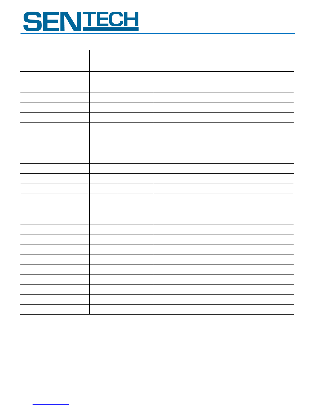
GenICam command
Camera command
Device
Command
Function
Width
100000
56-57H
Width for AOI (pixel)
Height
100000
52-53H
Height for AOI (pixel)
PixelFormat
000000
12H.6-7
Video out (bit)
OffsetX
100000
54-55H
X offset for AOI (pixel)
OffsetY
100000
50-51H
Y offset for AOI (pixel)
BinningVertical
000000
10H.4
Binning
ExposureMode
000000
10H.5
Trigger mode
ExposureTimeRaw
000000
20-22H
Exposure time of the electronic shutter
ExposureAuto
100000
20H.2
Shutter mode
AcquistionFrameRate
000000
58-5CH
Frame rate
TriggerDelay
000000
50-53H
The delay time for the trigger signal
TriggerActivation
000000
10H.6
Trigger polarity
TriggerSource
000000
12H.5
Trigger signal type
TriggerSoftware
000000
16H.0
Generate command software trigger
TriggerSoftwareSource
000000
16H.6-7
Software trigger source selection
TriggerMode
000000
11H.3
Function mode
LineSource0
000000
F0H.0-3
Output signal for 2 pin of the power-I/O connector
LineSource1
000000
F0H.4-7
Output signal for 3 pin of the power-I/O connector
UserOutputValue0
000000
F1H.3
UserOutput signal for 2 pin of the power-I/O connector
UserOutputValue1
000000
F1H.4
UserOutput signal for 3 pin of the power-I/O connector
LineInverter0
000000
5DH.0
Output signal polarity for 2 pin of the power-I/O connector
LineInverter1
000000
5DH.1
Output signal polarity for 3 pin of the power-I/O connector
StrobeSignalOnTime
000000
90-93H
Strobe signal active time
StrobeSignalDelay
000000
54-57H
The delay time for the strobe signal (us)
STC-GEC83A
E. GenICam / Camera Command Reference Table
User Guide 39 Rev 1.01
Page 40
STC-GE83A
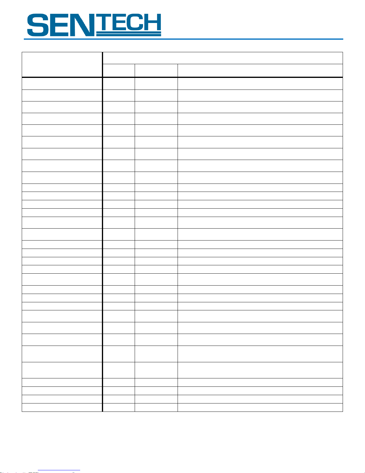
GenICam command
Camera command
Device
Command
Function
BalanceWhiteAuto
100000
40H.0-2
White balance mode
BalanceRatio_R_Preset1
100000
41H
Preset1 white balance (Red gain)
BalanceRatio_Gr_Preset1
100000
42H
Preset1 white balance (Gr gain)
BalanceRatio_B_Preset1
100000
43H
Preset1 white balance (Blue gain)
BalanceRatio_Gb_Preset1
100000
44H
Preset1 white balance (Gb gain)
BalanceRatio_R_Preset2
100000
45H
Preset2 white balance (Red gain)
BalanceRatio_Gr_Preset2
100000
46H
Preset2 white balance (Gr gain)
BalanceRatio_B_Preset2
100000
47H
Preset2 white balance (Blue gain)
BalanceRatio_Gb_Preset2
100000
48H
Preset2 white balance (Gb gain)
BalanceRatio_R_Preset3
100000
49H
Preset3 white balance (Red gain)
BalanceRatio_Gr_Preset3
100000
4AH
Preset3 white balance (Gr gain)
BalanceRatio_B_Preset3
100000
4BH
Preset3 white balance (Blue gain)
BalanceRatio_Gb_Preset3
100000
4CH
Preset3 white balance (Gb gain)
BalanceRatio_R_Once
100000
80H
Push to set white balance (Red gain)
BalanceRatio_Gr_Once
100000
81H
Push to set white balance (Gr gain)
BalanceRatio_B_Once
100000
82H
Push to set white balance (Blue gain)
BalanceRatio_Gb_Once
100000
83H
Push to set white balance (Gb gain)
GainAuto
100000
20H.3
AGC
GainRaw
000000
30H
CDS gain
SmearHalfReduction
000000
11H.4
Smear half reduction
GammaMode
100000
60H.0
Gamma table ON/OFF
ReloadGammaData
100000
60H.7
Gamma table ON/OFF
LensManualAdjustment
100000
92H.0-1
Iris lens manual adjustment operation
LensIrisAdjustment
100000
90H
Iris lens adjustment
PriorityMode
100000
20H.0
ALC control method priority
ALCIrisLens
100000
20H.1
Iris lens control method
Min_ShutterTime
100000
26-28H
The lower limit of the electronic shutter for auto shutter
(us)
Max_ShutterTime
100000
23-25H
The upper limit of the electronic shutter for auto shutter
(us)
AGCRange
100000
21H
AGC maximum limit
TargetBrightness
100000
2EH
Target brightness for ALC
ALC_Peak_Average
100000
2FH
ALC peak-average
DigitalGain
000000
31H
The digital gain
STC-GEC83A
User Guide 40 Rev 1.01
Page 41
STC-GE83A
GenICam command
Camera command
Device
Command
Function
ALCWeight1
100000
29H.0-3
Weight1 for ALC
ALCWeight2
100000
29H.4-7
Weight2 for ALC
ALCWeight3
100000
2AH.0-3
Weight3 for ALC
ALCWeight4
100000
2AH.4-7
Weight4 for ALC
ALCWeight5
100000
2BH.0-3
Weight5 for ALC
ALCWeight6
100000
2BH.4-7
Weight6 for ALC
ALCWeight7
100000
2CH.0-3
Weight7 for ALC
ALCWeight8
100000
2CH.4-7
Weight8 for ALC
ALCWeight9
100000
2DH.0-3
Weight9 for ALC
ALCWindowV1
100000
30-31H
Vertical1 position for the ALC weight area (pixel)
ALCWindowV2
100000
32-33H
Vertical2 position for the ALC weight area (pixel)
ALCWindowV3
100000
34-35H
Vertical3 position for the ALC weight area (pixel)
ALCWindowV4
100000
36-37H
Vertical4 position for the ALC weight area (pixel)
ALCWindowH1
100000
38-39H
Horizontal1 position for the ALC weight area (pixel)
ALCWindowH2
100000
3A-3BH
Horizontal2 position for the ALC weight area (pixel)
ALCWindowH3
100000
3C-3DH
Horizontal3 position for the ALC weight area (pixel)
ALCWindowH4
100000
3E-3FH
Horizontal4 position for the ALC weight area (pixel)
WB_WindowH1
100000
58-59H
Vertical1 position for the white balance area
WB_WindowH2
100000
5A-5BH
Vertical2 position for the white balance area
WB_WindowV1
100000
5C-5DH
Horizontal1 position for the white balance area
WB_WindowV2
100000
5E-5FH
Horizontal2 position for the white balance area
WB_WindowMode
100000
60H.4
White balance area ON/OFF
YThreshold
100000
4E-4FH
Bright level threshold for auto white balance
STC-GEC83A
User Guide 41 Rev 1.01
Page 42

STC-GE83A
STC-GEC83A
Caution:
Width, Height and PixelFormat all effect the image data size.
Please use GenICam command name command when changing these values, as exampled in the following sample code.
In the case to change the Width
BOOL SetWidth( PvDevice *pDevice, PvInt64 lValue )
{
PvGenInteger* lGenInteger = dynamic_cast<PvGenInteger*>( pDevice->GetGenParameters()->Get( "Width" ) );
PvResult lResult = lGenInteger->SetValue(lValue);
return lResult.IsOK();
}
User Guide 42 Rev 1.01
Page 43
STC-GE83A
Rev.
Date
Change
Notes
1.0
Aug. 17, 2011
New Document
1.01
Aug 24, 2011
Changed FrameActive to SensorReadOut
1.02
July 30, 2012
Updated:
Camera Control Command
GenICam Command
Communication Protocol
STC-GEC83A
Revision
User Guide 43 Rev 1.01
Page 44

STC-GE83A
STC-GEC83A
Sensor Technologies America, Inc.
1345 Valwood Pkwy, Suite 320
Carrollton, Texas 75006-6891
TEL (972) 481-9223 FAX (972) 481-9209
URL http://www.sentechamerica.com/
Sensor Technology Co., Ltd.
7F, Harada Center Building
9-17, Naka cho 4chrome
Atsugi-city, Kanagawa
243-0018 Japan
TEL +81-46-295-7061 FAX +81-46-295-7066
URL http://www.sentech.co.jp/
Taiwan Sensor Technology, Inc.
3F-6, No. 9, Aiguo W, Rd,. Jhong Jheng District
Taipei City 100, Taiwan, R.O.C.
TEL 886-2-2383-2331 FAX 886-2-2370-8775
EMAIL: [email protected]
User Guide 44 Rev 1.01
 Loading...