


No. 15S044-02
1
STC-CMC120ACXP / STC-CMB120ACXP
Specifications and Users guide
12 Meg CMOS Color / Monochrome
CoaXPRess Camera
STC-CMC120ACXP (12M Color)
STC-CMB120ACXP (12M Monochrome)
Product Specifications and Users guide
Sentech Co., Ltd

No. 15S044-02
2
STC-CMC120ACXP / STC-CMB120ACXP
Specifications and Users guide
Table of Contents
1 OVERVIEW ................................................................................................................................................................ 4
1.1 FEATURES .................................................................................................................................................................... 4
1.2 NAMING METHOD .......................................................................................................................................................... 4
2 SPECIFICATIONS ..................................................................................................................................................... 5
2.1 ELECTRONIC SPECIFICATIONS / MECHANICAL SPECIFICATIONS / ENVIRONMENTAL SPECIFICATIONS..................................... 5
2.1.1 STC-CMC120ACXP (Color)/STC-CMB120ACXP (Monochrome) ................................................................... 5
2.2 SPECTRAL SENSITIVITY CHARACTERISTICS .................................................................................................................... 6
2.2.1 STC-CMC120ACXP / STC-CMB120ACXP ....................................................................................................... 6
2.3 IO CONNECTOR ............................................................................................................................................................ 7
2.3.1 Pin assignment .................................................................................................................................................. 7
2.3.2 Input Output DC characteristics *1 ................................................................................................................. 7
2.3.3 Default Setting of Input Output ....................................................................................................................... 8
2.3.4 GPIO Circuit (Input) ......................................................................................................................................... 8
Input Signal Functions................................................................................................................................................. 8
General Purpose Input (Reference 1) .......................................................................................................................... 8
Input Response Characteristics ................................................................................................................................... 8
2.3.5 GPIO Circuit (Output) ....................................................................................................................................... 9
Output Signal Functions .............................................................................................................................................. 9
General Purpose Output (Reference 2) ..................................................................................................................... 10
General Purpose Output (Reference 3) ..................................................................................................................... 10
Characteristics of the output signals ........................................................................................................................ 10
2.4 CONECTOR INDICATOR LAMPS .......................................................................................................................................11
3 DIMENSIONS .......................................................................................................................................................... 12
3.1 TOP MODEL ................................................................................................................................................................ 12
3.2 STRAGIHT MODEL ....................................................................................................................................................... 13
4 CAMERA OPERATION............................................................................................................................................ 14
4.1 GENICAM COMMAND REFERENCE TABLE ..................................................................................................................... 14
4.2 FRAME RATE CALCULATION FOMULA ............................................................................................................................. 16
4.3 SAVING AND LOADING A DATA ....................................................................................................................................... 16
4.3.1 Save Setting ..................................................................................................................................................... 16
4.3.2 Load Setting ..................................................................................................................................................... 17
4.3.3 Camera startup ................................................................................................................................................ 17
4.3.4 Camera initialization ....................................................................................................................................... 17
5 REVISION HISTORY .............................................................................................................................................. 18

No. 15S044-02
3
STC-CMC120ACXP / STC-CMB120ACXP
Specifications and Users guide
Product Precautions
Handle the camera with care. Do not abuse the camera. Avoid striking or shaking it. Improper handling or storage
could damage the camera.
Do not pull or damage the camera cable.
During camera use, do not wrap the unit in any material. This will cause the internal temperature of the unit to
increase.
Do not expose the camera to moisture, or do not try to operate it in wet areas.
Do not operate the camera beyond its temperature, humidity and power source ratings.
While the camera is not being used, keep the lens or lens cap on the camera to prevent dust or contamination from
getting in the CCD or filter area and scratching or damaging this area.
Do not keep the camera under the following conditions:
• In wet, moist, and high humidity areas
• Under hot direct sunlight
• In high temperature areas
• Near an object that releases a strong magnetic or electric field
• Areas with strong vi brati on s
Apply the power that satisfies the requirements specified in this document to the camera.
Use a soft cloth to clean the camera. Use pressured air spray to clean the surface of the glass. DO not scratch the
surface of the glass.
The camera is a general-purpose electronic device; using the camera for the equipment that may threaten human
life or cause dangers to human bodies directly in case of failure or malfunction of the camera is not guaranteed.
Use the camera for special purposes at your own risk.

No. 15S044-02
4
STC-CMC120ACXP / STC-CMB120ACXP
Specifications and Users guide
1 Overview
This document describes the specifications of the following cameras
STC-CMC120ACXP (12M Color)
STC-CMB120ACXP (12M Monochrome)
1.1 Features
CMOS Sensor (Gl ob al Shu tter )
CoaXPress (later CXP) Interface
Maximum 180 fps on 12M pixel(8bit)
1.2 Naming Method
STC-CMx120ACXP-x
Figure 1. Naming Method
C: Color
B: Monochrome
Resolution
120: 12M Pixel
Sensor Size
A: 1.76”
CXP: CoaXPress
F: F Mount
T: T op Angle Type
None: Straight Type

No. 15S044-02
5
STC-CMC120ACXP / STC-CMB120ACXP
Specifications and Users guide
2 Specifications
2.1 Electronic specifications / M echanical specifications / Env ir onmental specifications
2.1.1 STC-CMC120ACXP (Color)/STC-CMB120ACXP (Monochrome)
Table 1. Specifications
*1: When CH1 was connected with Frame Grabber (FG), then FG provides camera power through PoCXP. Some kind of FG
start discovery when CH1 was connected. In this case camera may not be recognized as CXP-6(6.25Gbps) 4 Lane camera.
In order to recognai ze as C XP-6(6.25Gbps ) 4 Lane ca m era, pleas e co nnect C H1 after connecte d C H2, CH 3, CH4, or re do
discovery.
Product
STC-CMC120ACXP
STC-CMB120ACXP
Electronic
specifications
Imager
1.76 “ Type 12Meg color
progressive CMOS
(CMOSIS: CMV12000)
1.76” Type 12Meg monochrome
progressive CMOS
(CMOSIS: CMV12000)
Shutter
Global Shutter
Active picture elements
4096 (H) x 3072 (V)
Chip size
22.5 × 16.9 mm
Cell size
5.5 (H) x 5.5 (V) µm
Scanning system
Progressive
Scanning method
Full scanning, Variable ROI
Frame rate
180fps (8bit 4-Lane)
Video Output Interface
CXP-6(6.25Gbps) 4 Lane
Noise level
8bit
≤ TBD Digit (Gain 0 dB)
Minimum scene
illumination
TBD Lux at F2.25
TBD Lux at F2.25
Sync. System
Internal
Shutter speed
16[us] to 16[s]
Gain
Digital
1 to x5
Analog
x1,x2,x3
Trigger Mode
FreeRun / Edge Preset Trigger / Pulse Width Trigger / CXP Tigger Packet
Communication
Protocol: CoaXPress Standard Version 1.1
Interface: GenIcam
ROI
Adjustable Steps for image size: 16 pixels in horizontal direction and 4 lines in vertical
I/O
3 GPIO
Binning
N/A
HDR
Support
Pixel Defect Correction
Support
Vertical Line Correction
Support
Power
Input Source
PoCXP, (IO connector CH1 Only) *1
Input voltage
TBD (18.5Vdc to 26Vdc (24V Nominal))
Consumption
TBD
Mechanical
specifications
Dimensions
68 (W) x 68 (H) x 40 (D) mm (Excluding the connector)
Optical filter
No IR cut filter
Material
Aluminum alloy
Lens mount
M42×P1.0, FB = 10.0mm (in Air)
Interface connector
CXP connector (camera: DIN1.0/2.3, Jack x 4, 75Ω)
Power/IO connector: HR10A-7R-6PB (Hirose) or equivalent
Weight
TBD
Environment
al
specifications
Operational temperature
TBD (-5 to 40 deg. C)
Storage temperature
TBD (-30 to 65 deg. C)
Vibration
20Hz to 200Hz to 20Hz (5min./cycle), acceleration 10G, XYZ 3 directions 30 min. each)
Shock
Acceleration 38G, half amplitude 6ms, XYZ 3 directions 3times each
Standard compliancy
EMS: EN61000-6-2, EMI: EN55022 (Class B) (To be obtained)
RoHS
RoHS,REACH compliance

No. 15S044-02
6
STC-CMC120ACXP / STC-CMB120ACXP
Specifications and Users guide
2.2 Spectral Sensitivity Characteristics
2.2.1 STC-CMC120ACXP / STC-CMB120ACXP
Figure 2. Spectral Sensitivity Characteristics

No. 15S044-02
7
STC-CMC120ACXP / STC-CMB120ACXP
Specifications and Users guide
2.3 IO Connector
HR10A-7R-6PB (Hirose) or equivalent.
This connector is for input and output signals.
The trigger input and sync input /output signals can be assigned through the camera setting
communication. As for the cable part (Female connector), HR10A-7P-6S (Hirose) or equivalent can be
used.
2.3.1 Pin assignment
*Possible Maximum Rated Voltage is +24V.on GPIO0, GPIO1 and GPIO2.
*Please set electrically “OPEN” on NC (Pin 6).
2.3.2 Input Output DC characteristic s *1
Pin
No.
Signal Name
Function
IN/OUT
Voltage
Current
Reference
Low Voltage
High Voltage
1
GND
GND
- -
-
2
GPIO2
General Purpose
Input Output
IN/OUT
IN
Less than+1.00V
+3.00 to +24V
4uA(typ.)
2
OUT
0 to +2.20V
+3.00 to +24V
15mA (Max.)
3,4
3
GPIO1
General Purpose
Input Output
IN/OUT
IN
Less than+1.00V
+3.00 to +24V
4uA(typ.)
2
OUT
0 to +2.20V
+3.00 to +24V
15mA (Max.)
3,4
4
GPIO0
General Purpose
Input Output
IN/OUT
IN
Less than+1.00V
+3.00 to +24V
4uA(typ.)
2
OUT
0 to +2.20V
+3.00 to +24V
15mA (Max.)
3,4
5
N.C.
NC
- - -
-
6
N.C.
NC
- - -
-
*1) These values on the table are just reference number, please evaluate carefully when these IO are used.
Pin No.
Signal Name
IN/OUT
1
GND
- 2 GPIO2
IN/OUT
3
GPIO1
IN/OUT
4
GPIO0
IN/OUT
5
NC - 6
NC
-
No. 15S044-02
8
STC-CMC120ACXP / STC-CMB120ACXP
Specifications and Users guide
2.3.3 Default Setting of Input Output
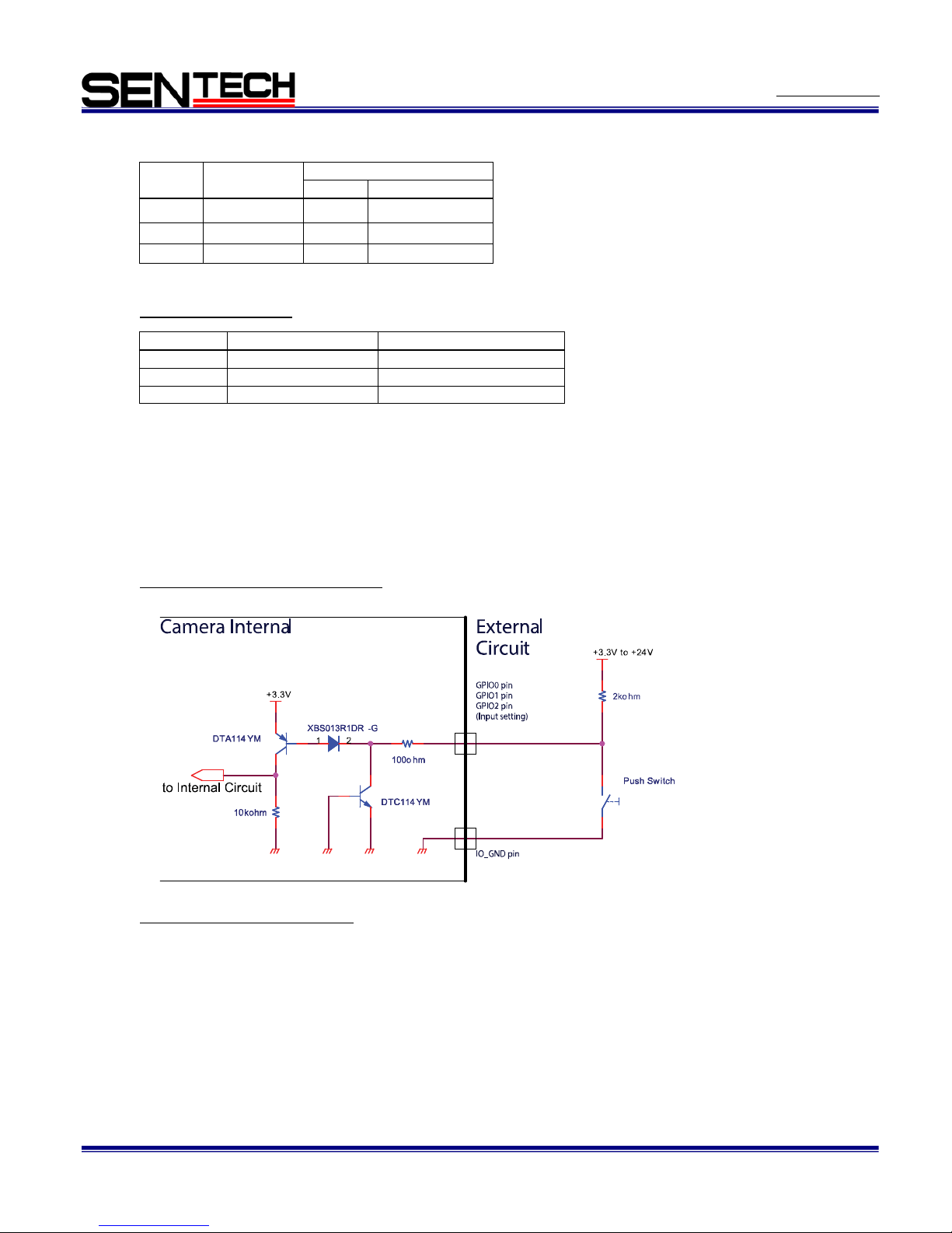
2.3.4 GPIO Circuit (Input)
Input Signal Functions
1) Disable
This function should be set when no input signal is neces s ar y.
2) General Input
This function can set high o r low level and the user can use this to check the status on the software.
3) Trigger Input
This function is used for the trigger signal in the edge preset mode.
General Purpose Input (Reference 1)
Input Response Characteristic s
TBD
Pin No.
Signal Name
Default
IN/OUT
Setting
2
GPIO2
IN
Disable
3
GPIO1
IN
Disable
4
GPIO0
IN
Disable
No.
Function
Polarity
1)
Disable (Default)
-
2)
General Input
-
3)
Trigger Input
Positive or Negative

No. 15S044-02
9
STC-CMC120ACXP / STC-CMB120ACXP
Specifications and Users guide
2.3.5 GPIO Circuit (Output)
Output Signal Functions
1) Disable
This function should be set when no output signal is necessary.
2) General Output
This function outputs high or low level signals set on the software.
6) Frame End
This function outputs when exposure ended with the with pulse delay setting and pulse duration applied.
8) Exposure Active
This function outputs the High or Low signal while in actual exposure time.
No/
Function
Polarity
1)
Disable (Default)
-
2)
General Output(UserOutput0/1/2)
-
6)
Frame End
Positive or Negative
8)
Exposure Active
Positive or Negative

No. 15S044-02
10
STC-CMC120ACXP / STC-CMB120ACXP
Specifications and Users guide
General Purpose Output (Reference 2)
General Purpose Output (Reference 3)
Characteristics of the outp ut signals
Response characteristics of the General Purpose output (Reference 2), and General Purpose output (Reference 3)
are shown in the diagram below. Pulse width is configurable through soft ware.
Please refer to the following response timing table.
*1:
Reference 2. Measured on +1.8V internal Voltage.
*2:
Reference 3
VCCext
OPEN(*1)
5V (*2)
12V (*2)
24V (*2)
Td
1.82 usec
1.72 usec
1.77 usec
1.72 usec
Tr
8.58 usec
0.97 usec
0.91 usec
0.89 usec
Ts
0.11 usec
0.12 usec
0.14 usec
0.15 usec
Tf
0.10 usec
0.13 usec
0.23 usec
0.36 usec
Camera internal
USER_OUTPUT
Internal Voltage
0V
+3.3V or VCCext
IO_GND
No. 15S044-02
11
STC-CMC120ACXP / STC-CMB120ACXP
Specifications and Users guide
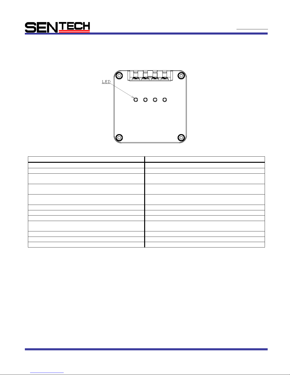
2.4 Conector indicator lamps
Conector indicator LED exists beside of each DIN connector.
Each LED informs each status of communication. The detail of status is as following table.
Status
LED Flicker Pattern
No power
Off
System booting
Solid orange
Powered, but nothing connec ted
(not applicable to a Device reliant on PoCXP power)
Slow pulse red
Connection detection in progress, PoCXP active
Fast flash alternate green / orange Shown f or a minimum
of 1s even if the connection detection is faster
Connection detection in progress, PoCXP not in use
Fast flash orange / Shown for a minimum of 1s even if the
connection detection is faster
Device / Host connected, but no data being transferred
Solid green
Device / Host incompatible, PoCXP active
Slow flash alternate red / green
Device / Host incompatible, PoCXP not in use
Slow flash alternate red / orange
Device / Host connected, waiting for event
(e.g. trigger, exposure pulse)
Slow pulse orange
Device / Host connected, data being transferred
Fast flash green.
Data Transfer Error
Red LED ON (500msec)
System Error
Red LED flicker fast
CH1 CH2 CH3
CH4

No. 15S044-02
12
STC-CMC120ACXP / STC-CMB120ACXP
Specifications and Users guide
3 Dimensions
3.1 Top Model

No. 15S044-02
13
STC-CMC120ACXP / STC-CMB120ACXP
Specifications and Users guide
3.2 Stragiht Model

No. 15S044-02
14
STC-CMC120ACXP / STC-CMB120ACXP
Specifications and Users guide
4 Camera Operation
4.1 GenICam Command Reference Table
GenICam command
Function
Width 4096 (pixel)
Height 3072 (pixel)
PixelFormat Format of the pixels provided by the device
ExposureMode Sets the operation mode of the Exposure (or shutter)
ExposureTime Sets the Exposure time
TriggerDelay
Specifies the delay in microseconds (us) to apply after the trigger
reception before activating it
TriggerSelector Selects the type of trigger to configure
TriggerSource
Specifies the internal sig nal or physical input L ine to use as the trigg er
source
TriggerSoftware Generates an internal trigger
TriggerMode Controls if the selected trigger is active
LineDebounceTime Sets the value of the input line debouncer time
LineSelector
Selects the physical line (or pin) of the external device connector to
configure
LineSource
Selects which interna l acquisition or I/O sourc e signal to output on th e
selected Line
UserOutputValue Sets the value of the bit selected by UserOutputSelector
LineInverter Controls the inversion of the signal of the selected input or output Line
UseroutputSelector
Selects which bit of the User Output register will be set by
UserOutputValue
TriggerOutOnTime Duration of TriggerOut signal when LineSource is set to TriggerOut(us)
TriggerOutDelay Delay of TriggerOut signal when LineSour c e is set to Tr iggerO ut( us)
StrobeOutDelay Delay of StrobeOut sig na l when Li ne Sourc e is set to Strob eOut( us )
GainSelector Selects which Gain is controlled by the various Gain features
Gain Controls the selected gain as an absolute physical value
BlackLevel Controls the black level as an absolute physical value
DeviceSerialNumber Device's serial number
DeviceTemperature Device temperature in degrees Celsius (C)
HDRMode Sets the HDR mode
HDRSlope HDR mode can choose 1slope,2slope or 3slope mode
HDRKnee1 The parameter sets it in % for the ExposureTime
HDRKnee2 The parameter sets it in % for the ExposureTime
HDRVlow1 Set the voltage of HDRVlow1 for the HDR saturation level
HDRVlow2 Set the voltage of HDRVlow2 for the HDR saturation level
Cxp Link Configuration CXP6_X4

No. 15S044-02
15
STC-CMC120ACXP / STC-CMB120ACXP
Specifications and Users guide
GenICam command
Function
Device T ap Geometry Geometry_1X_1Y
UserSetSelector Selects the feature User Set to load, save or configure
UserSetLoad
Loads the User Set specified by UserSetSelector to the device and
makes it active
UserSetSave
Save the User Set specified by UserSetSelector to the non-volatile
memory of the device
UserSetDefault
Selects the feature User Set to load and mak e active by default when
the device is reset

No. 15S044-02
16
STC-CMC120ACXP / STC-CMB120ACXP
Specifications and Users guide
4.2 Frame rate calculation fomula
The Frame rate can be configured by modified variable line number.
The Frame rate on configured line number is as following formula.
150 /258 /(Valiable Vertical Line Number +38) x 1000,000 [fps] (Round down to the second decima placel)
Valiable Vertical Line Number:Unit 4Line (Minimum 4 Lines)
*Frame rate does not change even if horizontal pixel number redouced.
[Reference Information]
Frame rate on minimum activate size (256(H) x 4(V)) is 13842.7[fps].
4.3 Saving and Loading a data
This camera can save and load the camera parameters. It is included restoring the factory defaults.
There are two kind of data are exist.
Default: The factory defaults data
UserSet1: User accessible data for saving
The data is loaded and written into in the register on RAM of camera.
These functions can be accessed through the parameters (UserSetSelector, UserSetDefault) and commands
(UserSetLoad, UserSetSave) on UserSetControl category of GenICam.
For the descriptions of the parameters and commands, please see the table as follow.
GenICam parameters
UserSetSelector
Enumeration
Selects the feature User Set to load from “Default”, “UserSet1”
UserSetDefault
Enumeration
Selects the feature User Set to load and make active by default
“Default”,” UserSet1” from when the device is reset
UserSetLoad
Command
Loads the User Set specified by UserSetSelector to the device and
makes it active
UserSetSave
Command
Save the User Set specified by UserSetSelector to the non-volatile
memory of the device
4.3.1 Save Setting
Setting Procedure
1. Set UserSet1 on the UserSetSelector
2. Execute UserSetSave
When execute UserSetSave, write the
camera setting information from the
RAM into memory area that was
selected on UserSetSelector.
Note: UserSetSave is not available
when Default on UserSetSelector was
selected
EEPROM
UserSet1
EEPROM
Default
RAM area
Register
UserSetSelector
Selector

No. 15S044-02
17
STC-CMC120ACXP / STC-CMB120ACXP
Specifications and Users guide
4.3.2 Load Setting
Setting Procedure
1. Set UserSet1 or Default on UserSetSelector
2. Execute UserSetLoad
4.3.3 Camera startup
Setting Procedure
1. Set UserSet1 or Default on UserSetDefault
4.3.4 Camera initialization
In order to initialize camera setting, please follow the procedure as bellow.
Write Defalut into UserSet1.
Setting Procedure
1. Set Default on UserSetSelector
2. Execute UserSetLoad
3. Set UserSet1 on UserSetSelector
4. Execute UserSetSave
When execute UserSetLoad, write the
camera setting information from the
RAM into memory area that was
selected on UserSetSelector.
When startup camera, write camera
setting information from memory area
into the RAM.
EEPROM
UserSet1
EEPROM
Default
RAM Area
Register
UserSetDefault
Selector
EEPROM
UserSet1
EEPROM
Default
RAM Area
Register
UserSetSelector
Selector

No. 15S044-02
18
STC-CMC120ACXP / STC-CMB120ACXP
Specifications and Users guide
5 Revision History
Rev
Date
Changes
Note
00
2015/06/04
Released: Production model
01
2015/08/17
Revised
Shutter Speed, ROI
02
2015/12/15
Revised
Added FPS calculation formula

No. 15S044-02
19
STC-CMC120ACXP / STC-CMB120ACXP
Specifications and Users guide
7F, Harada center building
9-17, Naka cho 4 chome
Atsugi-city, Kanagawa
243-0018 Japan
Sentech Co., Ltd
TEL +81-46-295-7061 FAX +81-46-295-7066
URL http://www.sentech.co.jp/
 Loading...