

Page 1
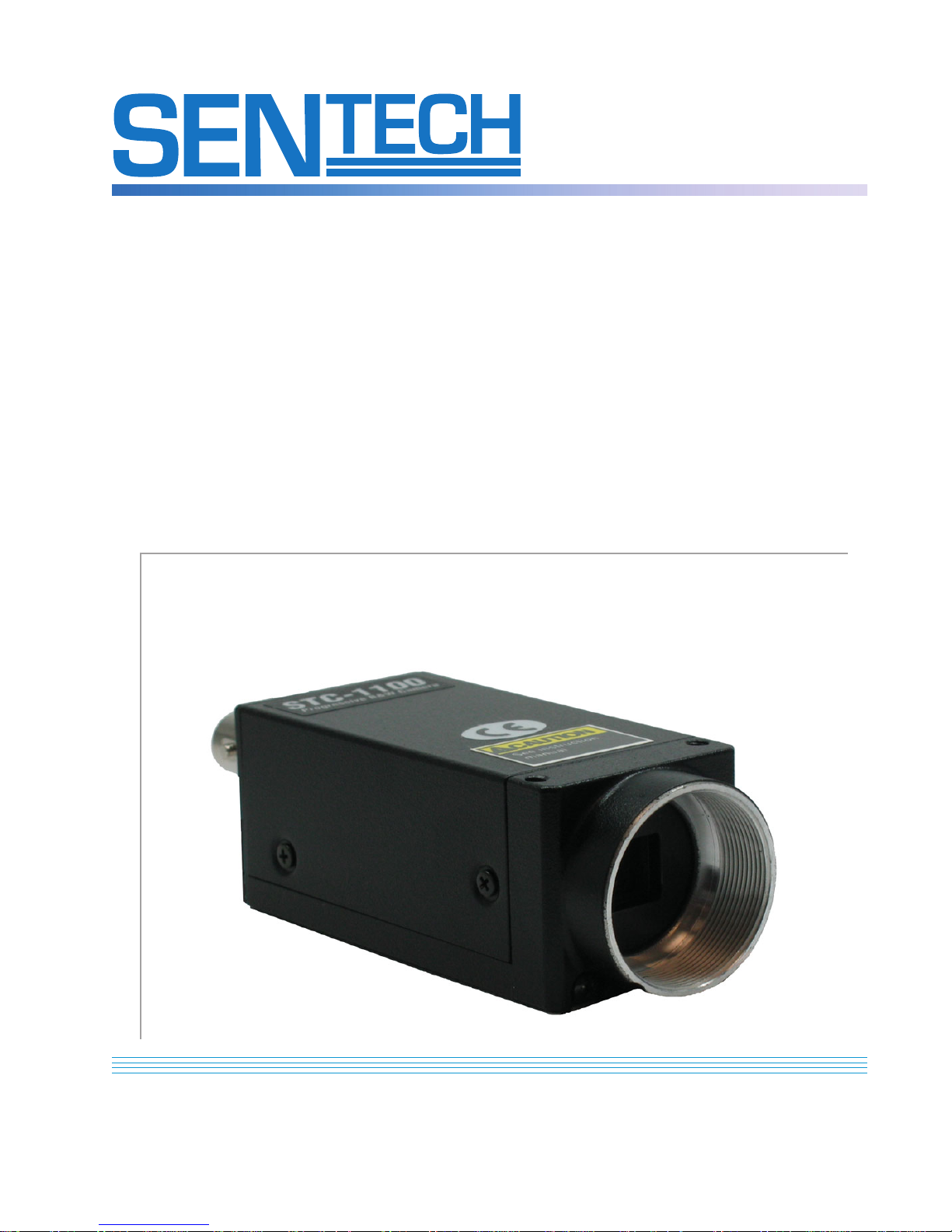
STC-1100C & STC-1100D Series
Operating Manual
Rev. 0.2 - Updated September 26, 2005
Double Speed
B&W Progressive Scan Camera
with
Variable Integration Random Shutter Trigger
and Vertical Reset
STC-1100C & STC-1100D
(Positive Enabled Trigger Pulse Input) (Negative Enabled Trigger Pulse Input)
Operating Manual
Sensor Technologies America, Inc.
Sensor Technologies America, Inc.
1345 Valwood Parkway, Suite 320 :: Carrollton, Texas 75006
1345 Valwood Parkway, Suite 320 :: Carrollton, Texas 75006
Phone: (972) 481-9223 :: Fax: (972) 481-9209 :: Toll Free: 1 (877) - SENTECH (736-8324)
Phone: (972) 481-9223 :: Fax: (972) 481-9209 :: Toll Free: 1 (877) - SENTECH (736-8324)
www.SentechAmerica.com
www.SentechAmerica.com
1
Page 2
STC-1100C & STC-1100D Series
Operating Manual
Rev. 0.2 - Updated September 26, 2005
Sensor Technologies America, Inc.
1345 Valwood Parkway, Suite 320 :: Carrollton, Texas 75006
Phone: (972) 481-9223 :: Fax: (972) 481-9209 :: Toll Free: 1 (877) - SENTECH (736-8324)
www.SentechAmerica.com
2
Page 3

STC-1100C & STC-1100D Series
Operating Manual
Rev. 0.2 - Updated September 26, 2005
Table of Contents
Precaution ............................................................................... 4
1. Specifications ..................................................................... 5
2. 12 Pin Connector .................................................................. 6
3. Switch Settings .................................................................... 7
4. Input Output Signals ....................................................... 10
5. Variable Integration Shutter Trigger Operations ................... 11
6. Vertical Reset Operations ...................................................... 13
7. Dimensions .......................................................................... 15
Sensor Technologies America, Inc.
1345 Valwood Parkway, Suite 320 :: Carrollton, Texas 75006
Phone: (972) 481-9223 :: Fax: (972) 481-9209 :: Toll Free: 1 (877) - SENTECH (736-8324)
www.SentechAmerica.com
3
Page 4

STC-1100C & STC-1100D Series
Operating Manual
Rev. 0.2 - Updated September 26, 2005
Precaution
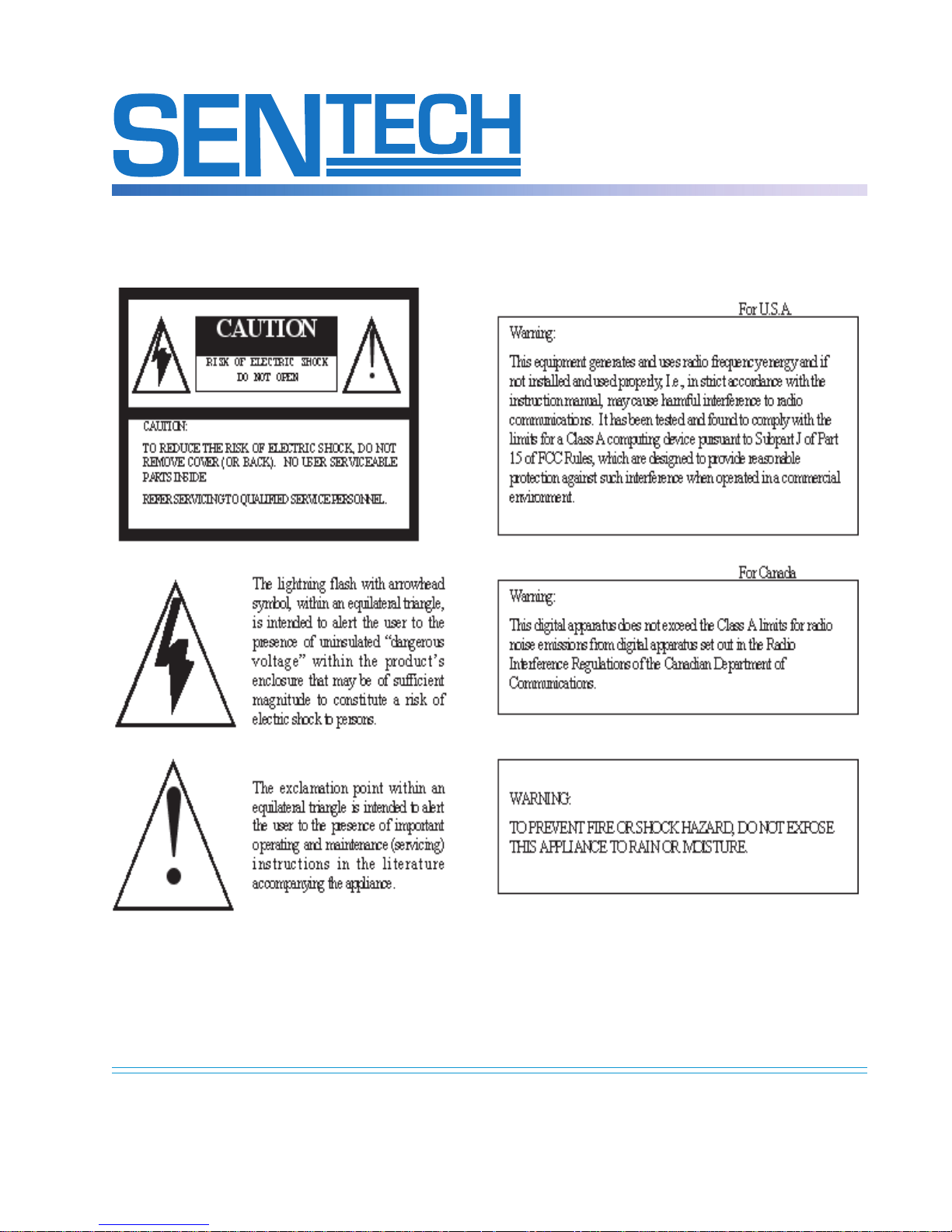
• Handle the camera with care. Do not abuse the camera. Avoid striking or
shaking it. Improper handling or storage could damage the camera.
• Do not pull or damage camera cable.
• During camera use, do not wrap the camera unit in any material. This will
cause the internal temperature of the unit to increase.
• Do not operate camera in wet areas and do not expose camera to
moisture.
• Do not operate camera beyond its maximum operating temperature,
humidity and power source ratings.
• To prevent dust or contamination from entering the CCD or filter area,
which could scratch or damage this area, keep lens or lens cap on camera
when camera is not in use.
• Do not expose the camera to the following conditions:
- Wet, moist and/or high humidity areas
- Hot direct sunlight
- High temperature areas
- Near objects that release strong magnetic or electric fields
- Strong vibration
• When cleaning the camera, use a soft cloth to clean the external areas of
the camera. Use a pressured air spray to clean the surface of the glass.
Do not scratch the surface of the glass.
• Use only a REGULATED POWER SUPPLY and supply the power with the
specified voltage.
Sensor Technologies America, Inc.
1345 Valwood Parkway, Suite 320 :: Carrollton, Texas 75006
Phone: (972) 481-9223 :: Fax: (972) 481-9209 :: Toll Free: 1 (877) - SENTECH (736-8324)
www.SentechAmerica.com
4
Page 5

STC-1100C & STC-1100D Series
Operating Manual
Rev. 0.2 - Updated September 26, 2005
1. Specifications
Image Sensor: 1/3” IT CCD
Effective Picture Element: 659(H) x 494(V)
Optical Black: Horizontal: 33 pixel
Vertical: 10 pixel
Chip Size: 5.84mm(H) x 4.94mm(V)
Cell Size: 7.4µm(H) x 7.4µm(V)
Scanning Area: 4.88mm(H) x 3.66mm(V)
Sync. System: Internal/External (HD & VD) Switchable
CCD V. Drive Frequency: Double Speed: 31.468KHz ±1%
Normal Speed: 15.734KHz ± 1%
CCD H. Drive Frequency: Double Speed: 24.5454MHz ± 1%
Normal Speed: 12.2727MHz ± 1%
Horizontal Resolution: 495 TVL
Vertical Resolution: 495 TVL
Scanning System: 525 Lines Progressive Scan or 2:1 Interlace
Scanning Frequency: Double Speed Pregressive: 59.94Hz(V), 31.468KHz(H)
Normal Speed Progressive: 29.97Hz(V), 15.734KHz(H)
Double Speed 2:1 Interlace: 119.88Hz(V), 31.468KHz(H)
Normal Speed 2:1 Interlace: 59.94Hz(V), 15.734KHz(H)
Minimum Illumination: Normal Speed:1 Lux @ F1.4
Double Speed: 2 Lux @ F1.4
S/N Ratio: >56dB
Gamma: 0.45 or 1 (Switchable)
Lens Mount: C-Mount
Gain: Manual/Fixed/Auto Gain Switchable
Shutter Speed: Normal: (8 Steps) 1/60 ~ 1/10,000 sec
Double: (8 Steps) 1/120 ~ 1/20,000 sec
Trigger Modes: One Pulse Variable Integration Shutter Trigger
STC-1100C : Positive Enabled Pulse Input
STC-1100D: Negative Enabled Pulse Input
Video Out: 1.0 Vp-p / 75Ω
Power Voltage: 10 - 14Vdc
Power Consumption: Normal Speed: 180mA
Double Speed: 210mA
Ambient Temperature: -10°C ± 50°C (14°F ± 122°F)
Dimensions: 31(W) x 29(H) x 73(D)mm (1.24” x 1.16” x 2.92”)
Weight: 85g
Sensor Technologies America, Inc.
1345 Valwood Parkway, Suite 320 :: Carrollton, Texas 75006
Phone: (972) 481-9223 :: Fax: (972) 481-9209 :: Toll Free: 1 (877) - SENTECH (736-8324)
www.SentechAmerica.com
5
Page 6
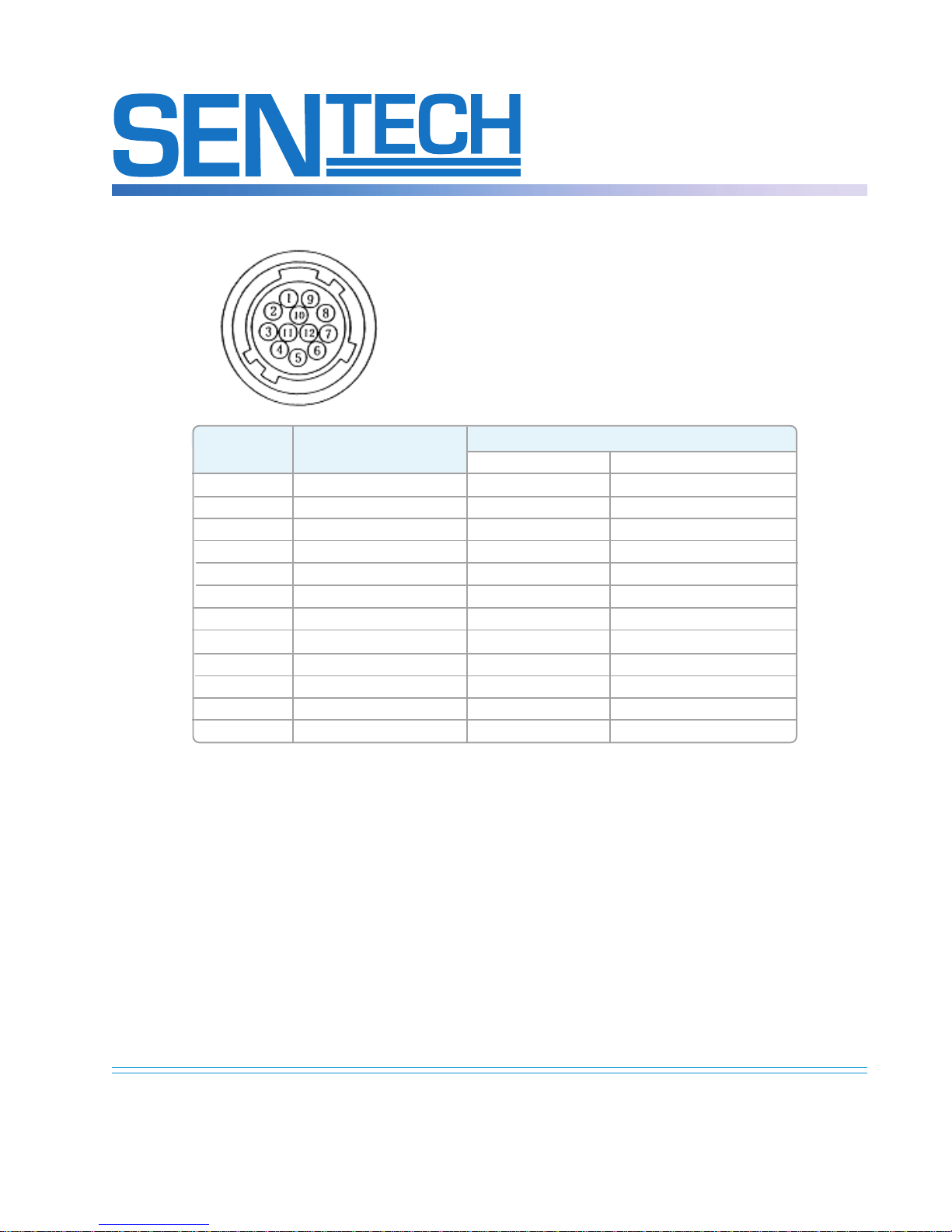
2. 12-Pin Connector Assignment
Note: Mating Connector: Hirose HR10-A-10P-12S
Pin No. Internal Sync External Sync
HD/VD Trigger Shutter
1 GND GND GND
2 +12Vdc +12Vdc +12Vdc
3 Video GND Video GND Video GND
4 Video Out Video Out Video Out
5 HD GND HD GND HD GND
6 Int. HD Out Ext. HD In Ext. HD In
7 Int. VD Out Ext. VD In
8 M-Trig GND
9 M-Trig In
10 GND GND
11
12 VD GND VD GND GND
STC-1100C & STC-1100D Series
Operating Manual
Rev. 0.2 - Updated September 26, 2005
Notes:
1) Internal Sync Mode or External Sync Mode can be selected by the switch
described in 3b.
When the External Sync Mode is selected and no external horizontal drive signal
(HD) is applied, the camera switches to internal sync mode automatically.
2) “M-trig In (Main Trigger Input)” is used for the variable integration shutter
trigger input and for:
3) The main trigger pulse input described in 4b.
Sensor Technologies America, Inc.
1345 Valwood Parkway, Suite 320 :: Carrollton, Texas 75006
Phone: (972) 481-9223 :: Fax: (972) 481-9209 :: Toll Free: 1 (877) - SENTECH (736-8324)
www.SentechAmerica.com
6
Page 7
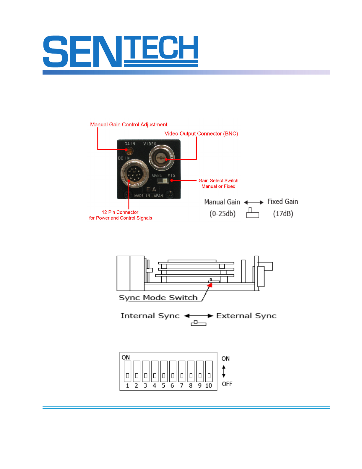
3. Switch Settings
a.) Fixed/Manual Gain Switch
STC-1100C & STC-1100D Series
Operating Manual
Rev. 0.2 - Updated September 26, 2005
b.) Sync Mode Switch
c.) DIP Switch
Sensor Technologies America, Inc.
1345 Valwood Parkway, Suite 320 :: Carrollton, Texas 75006
Phone: (972) 481-9223 :: Fax: (972) 481-9209 :: Toll Free: 1 (877) - SENTECH (736-8324)
www.SentechAmerica.com
7
Page 8

STC-1100C & STC-1100D Series
Operating Manual
Rev. 0.2 - Updated September 26, 2005
d.) DIP Switch Functions
Switch No. Position Function
1 ON Progressive Mode
OFF 2:1 Interlace
2 ON Normal (Internal or External Sync)
OFF Variable Integration Shutter Trigger
3 ON Normal Speed
OFF Double Speed
4 ON Manual or Fixed Gain Control
OFF Auto Gain Control
5 Shutter Speed (See the following chart)
6 Shutter Speed (See the following chart)
7 Shutter Speed (See the following chart)
8 Shutter Speed (See the following chart)
9 Shutter Speed (See the following chart)
10 ON N/A
OFF One-Pulse Variable Integration Shutter Trigger
Important: DIP Switch No. 5 must be turned ON and No.6 must be turned OFF when the
camera operates in the “Variable Integration Shutter Trigger Mode”.
e.) DIP Switch Functions
Mode Switch Number Shutter Speed (Sec.)
56789Normal Speed Double Speed
Flicker Less ON ON 1/100 1/200
OFF OFF OFF Shutter OFF
ON OFF OFF OFF OFF 1/60 1/120
ON OFF ON OFF OFF 1/125 1/250
High Speed ON OFF OFF ON OFF 1/250 1/500
Shutter ON OFF ON ON OFF 1/500 1/1000
ON OFF OFF OFF ON 1/1000 1/2000
ON OFF ON OFF ON 1/2000 1/4000
ON OFF OFF ON ON 1/4000 1/8000
ON OFF ON ON ON 1/10000 1/20000
Notes:
1. 1/30sec in Normal Speed Progressive Mode, 1/60sec in Normal Speed Interlace Mode
2. 1/60sec in Double Speed Progressive Mode, 1/120sec in DOuble Speed Interlace Mode
Important: DIP Switch No.5 must be turned ON and No.6 must be turned OFF when the camera operates
in the “Variable Integration Shutter Trigger Mode”.
Sensor Technologies America, Inc.
1345 Valwood Parkway, Suite 320 :: Carrollton, Texas 75006
Phone: (972) 481-9223 :: Fax: (972) 481-9209 :: Toll Free: 1 (877) - SENTECH (736-8324)
www.SentechAmerica.com
(Note 1)
Shutter OFF
(Note 2)
8
Page 9
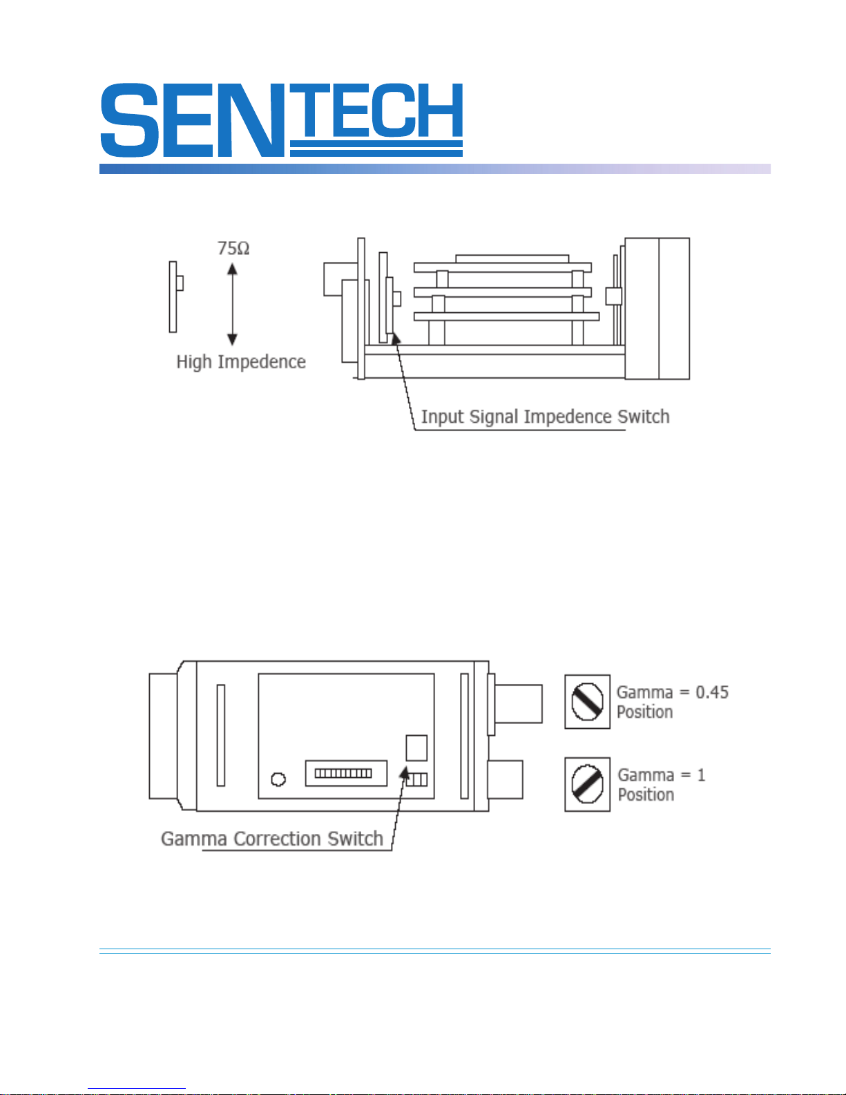
f.) Input Signal Impedence Switch
Notes:
1. This impedence switch controls both HD and VD input impedence.
2. Set this switch to “High Impedence” when the camera is used in the
variable integration shutter trigger mode.
STC-1100C & STC-1100D Series
Operating Manual
Rev. 0.2 - Updated September 26, 2005
g.) Camera Correction Switch
Sensor Technologies America, Inc.
1345 Valwood Parkway, Suite 320 :: Carrollton, Texas 75006
Phone: (972) 481-9223 :: Fax: (972) 481-9209 :: Toll Free: 1 (877) - SENTECH (736-8324)
www.SentechAmerica.com
9
Page 10

4. Input Output Signals
a) External Sync Input Signals
I) HD
Input Signal Level: 2-5Vp-p
Termination Impedence: 75Ω or high impedence
Sync Frequency: 15.734KHz ± 1%
II) VD
Input Signal Level: 2-5Vp-p
Termination Impedence: 75Ω or high impedence
Sync Frequency: 29.97Hz
b) Sync Output Signals
I) HD
Input Signal Level: 2-5Vp-p at 75Ω termination
Termination Impedence: 75Ω or high impedence
Sync Frequency: 15.734KHz ± 1%
II) VD
Input Signal Level: 2 Vp-p at 75Ω termination
Termination Impedence: 75Ω or high impedence
Sync Frequency: 29.97Hz
STC-1100C & STC-1100D Series
Operating Manual
Rev. 0.2 - Updated September 26, 2005
(Normal Speed Progressive)
31.468KHz ± 1% (Double Speed Progressive)
15.734KHz ± 1% (Normal Speed 2:1 Interlace)
31.468KHz ± 1% (Double Speed 2:1 Interlace)
(Normal Speed Progressive)
59.94Hz (Double Speed Progressive)
59.94Hz (Normal Speed 2:1 Interlace)
119.88Hz (Double Speed 2:1 Interlace)
5 Vp-p at high impedence
(Normal Speed Progressive)
31.468KHz ± 1% (Double Speed Progressive)
15.734KHz ± 1% (Normal Speed 2:1 Interlace)
31.468KHz ± 1% (Double Speed 2:1 Interlace)
5 Vp-p at high impedence
(Normal Speed Progressive)
59.94Hz (Double Speed Progressive)
59.94Hz (Normal Speed 2:1 Interlace)
119.88Hz (Double Speed 2:1 Interlace)
c) Variable Integration Shutter Trigger Input Signals
Low Level: 0-0.5V
High Level: 4-5V
Pulse Duration: Please see section 3
Sensor Technologies America, Inc.
1345 Valwood Parkway, Suite 320 :: Carrollton, Texas 75006
Phone: (972) 481-9223 :: Fax: (972) 481-9209 :: Toll Free: 1 (877) - SENTECH (736-8324)
www.SentechAmerica.com
10
Page 11

STC-1100C & STC-1100D Series
Operating Manual
Rev. 0.2 - Updated September 26, 2005
5. Variable Integration Shutter Trigger Operations
Note: Double Speed 2:1 Interlace mode is not used in these variable integration
shutter trigger operations.
Important: DIP Switch No. 5 must be turned ON and No. 6 must be turned OFF
when the camera operates in the “Variable Integration Shutter Trigger Mode”.
a) One Pulse Variable Integration Shutter Trigger Operations
I) Functions
With this “one-pulse Variable integration shutter trigger mode”, one
trigger pulse input signal can control camera’s integration time
based on its pulse duration time. In other words, the integration
time starts at the falling edge of the trigger oulse then ends at its
rising edge (see the drawing below). Since “XSUB” is activated in
the camera at the falling edge of the trigger pulse and “XSG” is
activated at the rising edge, the integration time is controlled very
accurately.
Video signal output is sent out frm the camera at the moment “t2” period
ends. “t2” starts at the rising edge of the trigger pulse and ends at the
18th internal HD pulse (2:1 Interlace Mode) or 33rd internal HD pulse
(Progressive Mode) after the rising edge of the trigger pulse. Therefore,
“t2” is exactly 19H (2: Interlace Mode) or 34H (Progressive Mode) if the
rising edge of the trigger oulse is synchronizing to the internal HD pulse.
In the case the rising edge of the trigger pulse is not synchronizing to the
internal HD pulse, this “t2” will fluctuate depending on the relational
timing of the two pulses as described in section 2.
This camera provides a capability to synchronize to External HD in the
variable integration shutter trigger mode. With this feature, user can
easily create HD-synchronized trigger pulse for the above mentioned
operation since the internal HD synchronizes to the external HD applied to
the camera.
Sensor Technologies America, Inc.
1345 Valwood Parkway, Suite 320 :: Carrollton, Texas 75006
Phone: (972) 481-9223 :: Fax: (972) 481-9209 :: Toll Free: 1 (877) - SENTECH (736-8324)
www.SentechAmerica.com
11
Page 12

STC-1100C & STC-1100D Series
Operating Manual
Rev. 0.2 - Updated September 26, 2005
II) Timing Chart
Note: Trigger input pulse must be positive (STC-1100C) or negative (STC-1100D)
enabled.
b) “T” - Integration period must be set within the following time length
Normal Speed Interlace: 100µmsec - 16.7msec
Normal Speed Progressive: 100µmsec - 16.7msec
Double Speed Progressive: 50µmsec - 8.3msec
c) “t1” - From the rising edge of the trigger pulse to the vertical sync pulse
Normal Speed Interlace: 4H + Td (19H with HD-synchronized trigger)
Normal Speed Progressive: 4H + Td (5H with HD-synchronized trigger)
Double Speed Progressive: 4H + Td (5H with HD-synchronized trigger)
d) “t2” - From the rising edge of the trigger pulse to the video out
Normal Speed Interlace: 18H + Td (19H with HD-synchronized trigger)
Normal Speed Progressive: 33H + Td (34H with HD-synchronized trigger)
Double Speed Progressive: 33H + Td (34H with HD-synchronized trigger)
e) Minimum trigger intervals are the following. Cycle speed of each trigger
must be greater than these values
Normal Speed Interlace: 18msec
Normal Speed Progressive: 36msec
Double Speed Progressive: 18msec
Sensor Technologies America, Inc.
1345 Valwood Parkway, Suite 320 :: Carrollton, Texas 75006
Phone: (972) 481-9223 :: Fax: (972) 481-9209 :: Toll Free: 1 (877) - SENTECH (736-8324)
www.SentechAmerica.com
12
Page 13
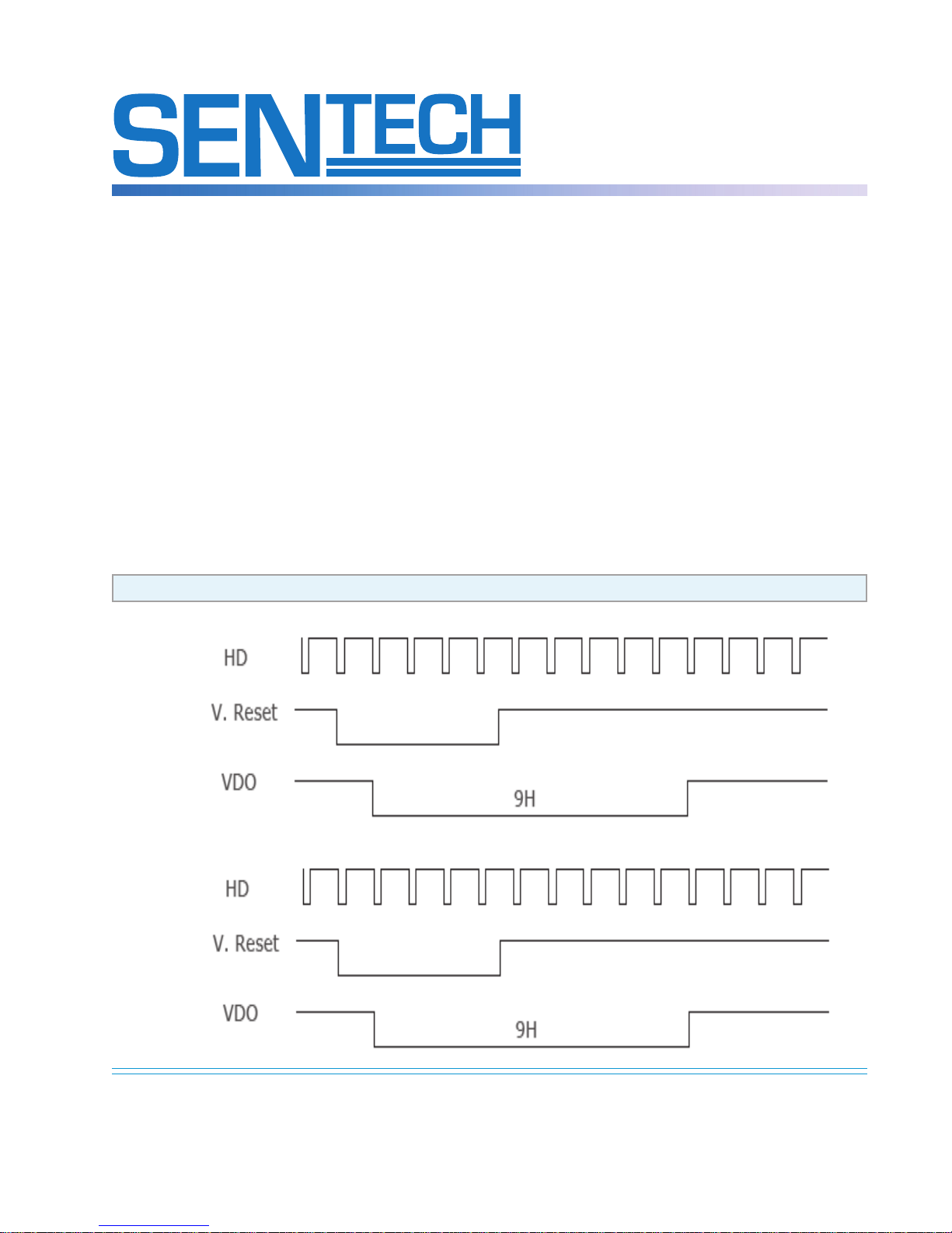
6. Vertical Reset Operations
In this “Vertical Reset Mode”, when the camera receives one VD pulse,
only one field of video signal (2:1 Interlace mode) or one frame of video
signal (progressive mode) is sent out.
1) Turn “Sync Mode Switch” (2.b) to “External Sync”
2) Turn DIP switch No. 2 (2:C:II) to “ON (Internal or External Sync)”. The
camera switches to external mode automatically when external HD is
supplied.
3) The vertical operates as “Direct Reset Mode”
4) In the case of 2:1 Interlace, even odd field is determined by the timing
of the falling edge of the vertical reset pulse (see note on next page)
6. Timing Chart
Normal and Double Speed 2:1 Interlace
a) Odd Field Reset
STC-1100C & STC-1100D Series
Operating Manual
Rev. 0.2 - Updated September 26, 2005
b) Even Field Reset
Sensor Technologies America, Inc.
1345 Valwood Parkway, Suite 320 :: Carrollton, Texas 75006
Phone: (972) 481-9223 :: Fax: (972) 481-9209 :: Toll Free: 1 (877) - SENTECH (736-8324)
www.SentechAmerica.com
13
Page 14
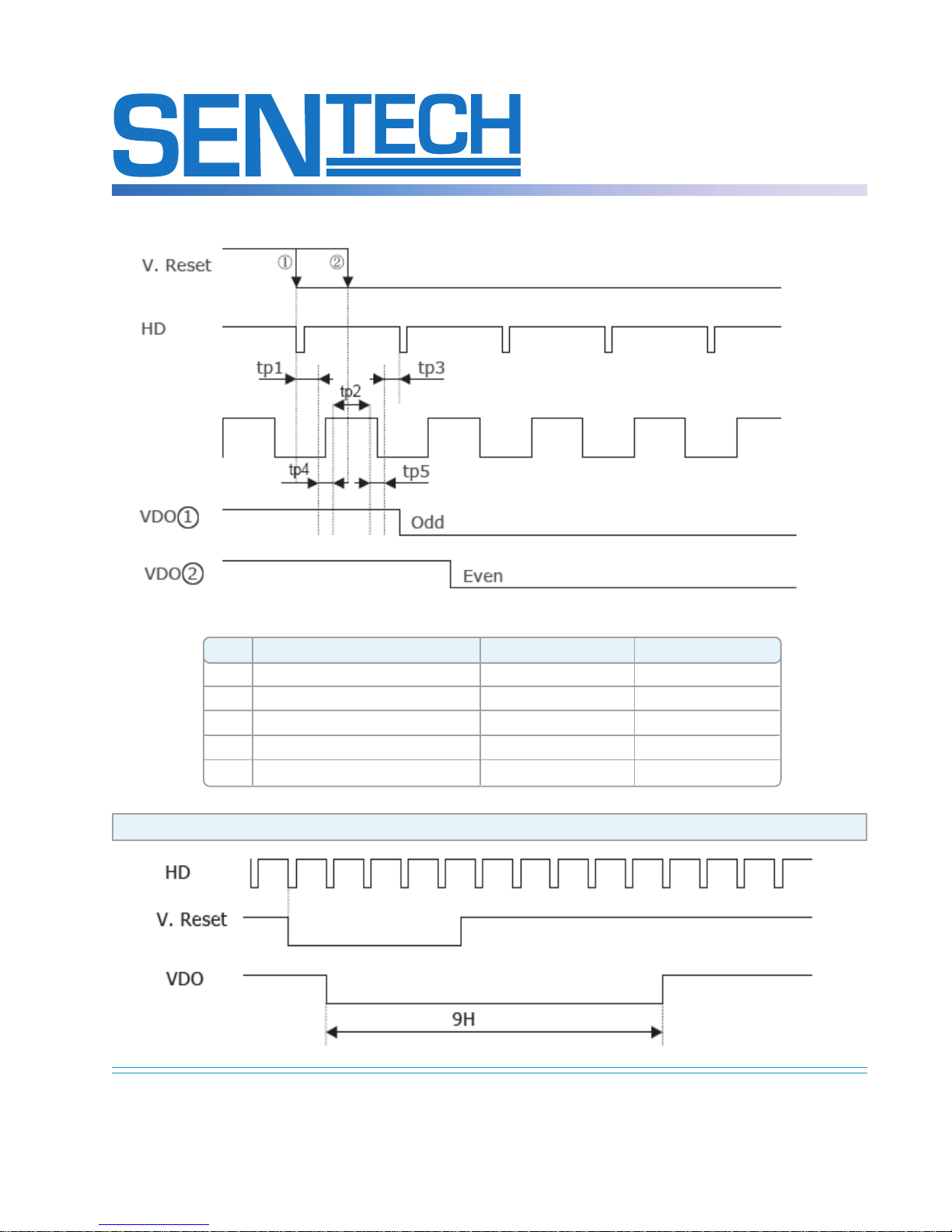
Note Field (odd or even) determination
STC-1100C & STC-1100D Series
Operating Manual
Rev. 0.2 - Updated September 26, 2005
Sign Definition Normal Speed Double Speed
tp1 Area to reset to Odd Field 21.9µs 11µs
tp2 Area to reset to Even Field 31.6µs 15.8µs
tp3 Area to reset to Odd Field - -
tp4 Prohibited Area 200ns 100ns
tp5 Prohibited Area 200ns 100ns
Normal and Double Speed Progressive Scan
Sensor Technologies America, Inc.
1345 Valwood Parkway, Suite 320 :: Carrollton, Texas 75006
Phone: (972) 481-9223 :: Fax: (972) 481-9209 :: Toll Free: 1 (877) - SENTECH (736-8324)
www.SentechAmerica.com
14
Page 15
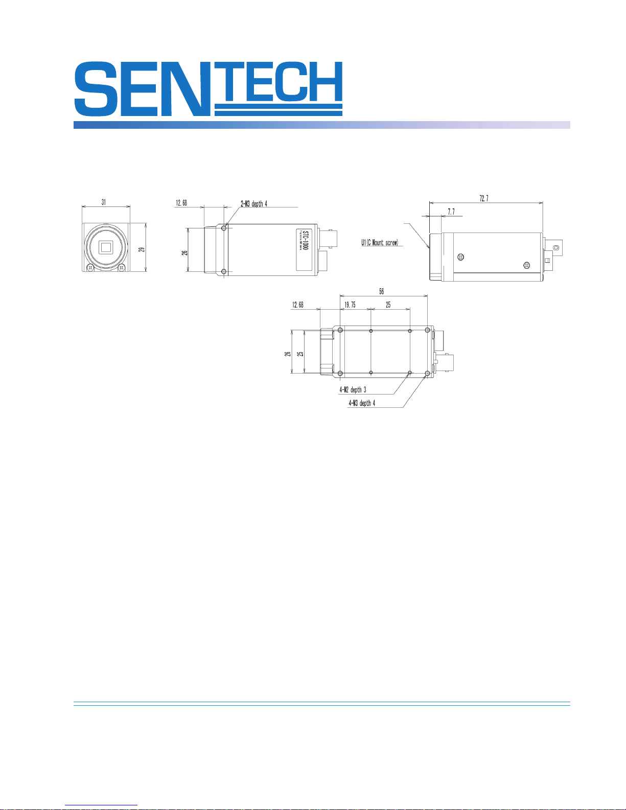
7. Dimensions
STC-1100C & STC-1100D Series
Operating Manual
Rev. 0.2 - Updated September 26, 2005
Sensor Technologies America, Inc.
1345 Valwood Parkway, Suite 320 :: Carrollton, Texas 75006
Phone: (972) 481-9223 :: Fax: (972) 481-9209 :: Toll Free: 1 (877) - SENTECH (736-8324)
Note: Measurements are given in mm
www.SentechAmerica.com
15
 Loading...