

SenTech IR-SNIF-MCD Series, IR-SNIF-MCD-16, IR-SNIF-MC-1, IR-SNIF-MCD-4, IR-SNIF-MCD-8 Installation And Operation Manual

INSTALLATION AND OPERATION MANUAL
ENVIRONMENTAL SYSTEM IR-SNIF-MCD
MODELS MCD-1, 4, 8 & 16
SenTech Corporation
5745 Progress Road
Indianapolis, Indiana 46241
888/248-1988
FAX 317/248-2014

APPLICABILITY
Information presented in this manual can be generally applied to all IR-SNIF-MCD refrigerant
monitors. Specific details of programming and operator interface apply to software version
5327K and later versions. To determine the version of an IR-SNIF-MCD, press the “*” key.
This will display momentary screens that provide contact information for SenTech Corporation,
the software version and any options enabled in the monitor. If your monitor has a version that
is older (smaller version number such as 2143), a version specific appendix A, Programming
and Operator Interface, is available. It can be downloaded from the SenTech Corporation
website, www.sentechcorp.com, or directly from SenTech Corporation at 888-248-1988.
ii

Contents
SAFETY PRECAUTIONS and WARNINGS............................................................................ 1
Models MCD-1, 4, 8 & 16 Specifications .................................................................................. 2
INTRODUCTION and OVERVIEW ......................................................................................... 3
Functional Description............................................................................................................ 3
Sensitivity to Refrigerants....................................................................................................... 8
Factory Calibration ................................................................................................................. 8
PPM vs. Leak Rate.................................................................................................................. 8
SYSTEM Block Diagram ........................................................................................................... 9
INSTALLATION ..................................................................................................................... 12
Unpack and Inspect Material ................................................................................................ 12
Identify Location for Monitor, Sample Points and Alarms .................................................. 12
Electrical Power Connection................................................................................................. 13
Electrical Alarm Connections ............................................................................................... 14
Other External Connections.................................................................................................. 15
STARTUP and PROGRAMMING........................................................................................... 18
Apply Power ......................................................................................................................... 18
Initial Screens........................................................................................................................ 18
Normal Operation ................................................................................................................. 19
Initial Programming .............................................................................................................. 19
FINAL TESTS .......................................................................................................................... 25
Monitor Sequencing.............................................................................................................. 25
Integration with External Devices ........................................................................................ 25
Response to Refrigerant........................................................................................................ 26
End-to-End System Test ....................................................................................................... 27
Documentation...................................................................................................................... 28
PREVENTIVE MAINTENANCE & REPAIR ........................................................................ 29
Preventive Maintenance........................................................................................................ 29
Commonly Ordered Parts ..................................................................................................... 29
Monitor Repair...................................................................................................................... 29
APPENDIX A: Programming and Operator Interface.............................................................. 30
Summary ............................................................................................................................... 30
Start-up Screens .................................................................................................................... 30
Operational Screens .............................................................................................................. 30
Menu Screens........................................................................................................................ 32
APPENDIX B: SenTech Room Volume Considerations ......................................................... 40
APPENDIX C: Parts List and Wire List................................................................................... 44
TROUBLESHOOTING GUIDE .............................................................................................. 47
SenTech Manufacturer's Limited Warranty.............................................................................. 50
iii

SAFETY PRECAUTIONS and WARNINGS
The following general safety precautions and warnings must be observed during all phases of
installation, operation, service and repair of equipment. Failure to comply with these
precautions, given here and elsewhere in the manual violates safety standards of design,
manufacture, and intended use. SenTech Corporation assumes no liability for the customer’s
failure to comply with these requirements.
Definitions of safety symbols used on equipment and in manuals.
AC Voltage Terminal: Indicates areas of equipment where AC line voltages are used
and present a potential risk of electrocution. Areas using line voltages should not be
accessed during operation.
AC-to-DC Power Supply: Indicates AC line voltages are used and present on portions
of the power supply, including the heat sinks. A potential risk of electrocution exists.
Areas using line voltages should not be accessed during operation.
Protective Grounding Terminal: The protective ground is to prevent electric shock in
case of an electrical fault. This symbol indicates that the terminal must be connected to
earth ground before operation of the equipment.
Caution: This sign calls attention to a procedure or practice which if not adhered to
could result in damage or destruction to a part of the product.
Other information and precautions:
Input Power: Power should be supplied through a two-pole circuit breaker located in a
reasonable proximity to the equipment. Ensure that the voltages are correct and an
appropriate ground connection is provided.
Do Not Open the Monitor with Power Applied: Line voltages exist on the terminal board
inside the monitor and on the power supply inside (including the heat sinks). The door to the
monitor and the power supply itself are marked with AC Voltage shock hazard warning labels.
Remove power prior to opening the door.
Installation, Maintenance and Repair: These functions should only be done by qualified
personnel following the instructions outlines in this manual. This is Installation Category III
equipment.
Pollution Degree: This equipment is designed for a Pollution Degree of 1.
Cleaning: This equipment should be cleaned by wiping with a soft clean cloth.
Intended Purpose: This equipment is designed to be used as a continuous refrigerant
monitor. It should not be used for any other purpose.
1

Models MCD-1, 4, 8 & 16 Specifications
Size: 16.5” x 15” x 6.75” (42cm x 38.1cm x 17cm)
Weight: Model MCD-1 - 30.4 lbs. (13.8 kg)
Model MCD-4 - 31.4 lbs. (14.2 kg)
Model MCD-8 - 33.8 lbs. (15.3 kg)
Model MCD-16 - 36.0 lbs. (16.3 kg)
Power: 120 or 240 Volts AC 50/60hz (41 Watts)
Temperature: 32 deg F – 125 deg F (0 deg C – 50 deg C)
Humidity: 0 – 95 % non-condensing
Atmospheric
Pressure:
Range: 0 – 1000 ppm Standard
Tube Length: 0 – 250 ft (0 – 76 m)
Sample
Areas:
Trip Point: Low Alarm 0 – 1000 ppm
Leak Wait: Varies from seven (7) seconds to three (3) minutes depending on
Alarm
Output:
Analog
Output:
Computer
Interface:
75-106 Kpa
Equipment rated for indoor use only
Model MCD-1 - 1 Area
Model MCD-4 - 4 Areas
Model MCD-8 - 8 Areas
Model MCD-16 - 16 Areas
Main Alarm 0 – 1000 ppm
High Alarm 0 – 1000 ppm
Horn Alarm Programmable to Low, Main or High
refrigerant concentration
Low, Main, High and Horn alarm relays, each with four (4) form C
contacts rated 5 amps maximum
0 – 10 volt proportional to 0 – 1000 ppm
4-20 mA (optional)
RS-485 (optional)
2

INTRODUCTION and OVERVIEW
The SenTech Environmental System IR-SNIF-MCD refrigerant monitor provides an early
warning of developing refrigerant leaks. The unit samples ambient air and measures the
amount of halogen based refrigerant gas in the air sample. When the proportion of refrigerant
present exceeds a trip point, the system goes into alarm mode. Should the system assess the
presence of refrigerant as a leak, using SenTech’s “LEAK WAIT” algorithm, the user is notified.
By discovering a leak shortly after it starts, the potential loss can be reduced to ounces of
refrigerant, saving money and helping protect the environment.
Functional Description
The refrigerant monitor is composed of four major functional blocks: Pneumatics, Infrared
Bench, Control Electronics and Power Supply. Refer to figure 1 for an overall block diagram.
The pneumatics pulls sample air or reference air from up to 250 feet and pumps the air
through a filter, to a pressure sensor, through the infrared bench and out the exhaust port of
the monitor. The infrared bench provides an infrared source and measures the presence of
refrigerant based on measured changes in the infrared light. The control electronics switches
the pneumatic valves from one area to reference air and on to the next area, measures and
stores the information from the infrared bench, provides a human machine interface for
programming and provides analog, digital and relay outputs to interface with building systems
and alarms.
Control Electronics
Press. Switch
IR Bench
LOW MAIN HIGH
TB6 (opt.)
TB3
Relays
Terminal Board
Terminal Board
Diaphragm Pump
HORN
Valve Driver Board
Power Supply
Valves
Area 1
Area 2
Area 3
Area 4
Area 5
Area 6
Area 7
Area 8
Reference Air
Exhaust
Figure 1 Overall Block Diagram
3

Pneumatics: Refer to the figure 2 for pneumatics block diagram. Tubing from the areas to be
monitored and from a reference air source (either fresh, outside air, or interior conditioned air
that is free of refrigerants) is connected to the valve manifold. The MCD1 has a single sample
valve and a reference valve, for a total of two valves. The MCD4 has four sample valves, the
MCD8 has eight and the MCD16 has 16, for a total of five, nine and seventeen valves
respectively. The electronics alternates between energizing the Sample air and the Auto zero
air valves. Following an Auto zero cycle, the pneumatics will be switched to the next sample
valve in order. The diaphragm pump draws air from the selected inlet and feeds the air
through a five micron filter, through an orifice restrictor, through the infrared bench and to the
exhaust port located on the lower right side of the unit. The pressure switch monitors the
pressure created by the flow from the pump and the restriction created by the orifice. Should
pressure fall, a flow failure is detected, and signal is sent to the electronics.
Press. Switch
IR Bench
Figure 2 Pneumatics Diagram
Valves
Area 1
Area 2
Diaphragm Pump
Area 3
Area 4
Area 5
Area 6
Area 7
Area 8
Reference Air
Exhaust
4

Infrared Bench: Refer to the figure 3 for Infrared Bench diagram. The infrared bench has an
integrated source circuit with infrared source at one end and an integrated detector circuit with
filter and detector at the other. Presence of refrigerant in the sample air will cause a change in
the output of the detector.
Control Electronics
IR Bench
Figure 3 Infrared Bench
5

Control Electronics: Refer to the figure 4 for control electronics block diagram. The signal
from the infrared bench is analyzed by the control circuit and converted into a digital
measurement in ppm (parts per million). The ppm level is compared to trip points set for Low,
Main and High alarm levels. If the ppm level exceeds the Low alarm threshold, the “Leak Wait”
algorithm is used to determine whether the monitor has experienced a transient exposure, or a
leak truly exists. If the ppm level remains above the Low alarm threshold on completion of leak
wait, the Low alarm relay is energized. If the signal continues to increase, the Main alarm
relay will be energized and ultimately the High alarm relay. Once the system enters Low, Main
or High alarm, it will remain in that mode until the problem is cleared and the system is reset.
Control Electronics
Press. Switch
TB4 (opt.)
TB3
IR Bench
Relays
LOW MAIN HIGH
Terminal Board
Terminal Board
HORN
Figure 4 Control Electronics Diagram
Valves
Area 1
Area 2
Area 3
Area 4
Area 5
Area 6
Area 7
Area 8
Valve Driver Board
POWER SUPPLY
Reference Air
6

Power Supply: Refer to the figure 5 for Power Supply diagram. Power is supplied to the
monitor through terminals 1, 2 and 3 of the terminal board. Line voltage is fed through the fuse
on the left side of the monitor (not shown), and to the diaphragm pump and power supply. The
power supply converts AC line voltage to dc voltage. DC Voltage is fed through the terminal
board to all of the electrical components of the monitor.
Control Electronics
Terminal Board
Power Supply
Figure 5 Power Supply Diagram
7

Sensitivity to Refrigerants
The system is sensitive in varying amounts
to all of the halogen-based refrigerants,
those containing molecules of fluorine,
chlorine or both. As part of the initial setup,
the specific refrigerant to be monitored is
entered into the system. The control
electronics compensates for the differing
sensitivities, resulting in a true ppm reading
for the refrigerant specified.
Factory Calibration
The IR-SNIF-MCD is calibrated at the
factory prior to shipment. The system
maintains accuracy through automatic
rezeroing. Periodically, the system
switches to the fresh air inlet, and
reestablishes a reference signal to which it
compares sample air. This process
eliminates the potential variations caused
by changes that develop in electronics as
components age. If a change in infrared
energy or detection of the infrared energy
develops, that change will be first measured
in the reference signal, then also in the
sample. The ppm level is based on the
ratio of the sample to the reference. This
ratio eliminates the effect of any variations,
and eliminates the need to periodically
calibrate a monitor in the field.
PPM vs. Leak Rate
The relationship between the actual amount
of product lost and the resulting ppm level
refrigerant in the air is complex. There is
no direct relationship between the amount
of refrigerant leaking and the concentration
being measured. The size of the room, the
location of the pick up point, the location of
the leak and airflow in the room will all
affect the actual concentration at the inlet.
However, by judicious location of the inlets
(see installation section) and maintaining
the alarm set points at a level not too far
above ambient, leaks should be detected
substantially before they otherwise would
be noticed. See Appendix B for a detailed
discussion of room volume considerations.
This appendix will help to provide a
correlation between pounds of refrigerant
lost over a given period to the ppm level
measured. This correlation can be
developed for a specific application.
8

SYSTEM Block Diagram
To Computer
To Phone Line
Analog To BMS
Binary To BMS
Binary To BMS
(rs-232)
(cat-3) (rs-232)
Item Part
Number
Monitor Model:
IR-SNIF-MCD1
IR-SNIF-MCD4
IR-SNIF-MCD8
IR-SNIF-MCD16
Sample Area
Connections:
Reference Air
Connection:
Power
Connection:
MCD1
MCD4
MCD8
MCD16
ACC 030
410144
410357
ACC 030
410144
410357
Field Wiring
From Circuit Breaker
(AC power)
l
e
t
o
r
o
t
m
n
e
o
R
C
m
k
m
n
o
i
L
C
m
e
d
o
M
(rs-485)
(0-10 vdc or optional 4-20mA)
(dry contacts)
(optional individual alarm relays - control voltage only)
Description Comments
1 to 16 sample tubes, routed to each
sample area
1 /4” OD 1/8” ID, FRPE Tube, 250 ft roll
Coarse Tube Filter
Barb Fitting for FRPE Tube
Reference air for ‘Auto Zero’
1 /4” OD 1/8” ID, FRPE Tube, 250 ft roll
Coarse Tube Filter
Barb Fitting for FRPE Tube
120 or 240 VAC
50/60 hz
12 or 14 AWG
To Fan Control
Reference Air
Horn
(switched AC)
Strobe
(switched AC)
Combo
(switched AC or control voltage)
(switched AC)
Valves
Area 3
Area 4
Area 5
Area 6
Area 7
Area 8
Exhaust
r
o
t
i
n
o
M
(sample tube and filter)
(sample tube and filter)
(sample tube and filter)
Area 1
Area 2
Terminate tube 12”-18” above floor
Purchased separately from monitor, or customer supplied
Included inside monitor
Included inside monitor
Terminate tube in area free of refrigerants and interfering
chemicals (12”-18” from ceiling if indoors)
Purchased separately from monitor, or customer supplied
Included inside monitor
Included inside monitor
Voltage jumper selected inside monitor
Provided by customer, Install in accordance with NEC and
local codes
9

Alarm
Connections:
Exhaust Fan
Control:
BMS Control
Connections:
Analog:
Binary:
ACC 020
ACC 026
ACC 025
Field Wiring
Field Wiring
---
OP 001
OP 001(2nd)
Field Wiring
---
OP 002
Field Wiring
Combination Horn/Strobe Alarm
120 vac alarm, surface mounted using
included 4x4 box, or flush mounted
using customer provided 4x4 box
installed in finished wall, horn and
strobe portions of alarm can be
controlled by separate relays, or
common relay, multiple tones available
(switch selectable inside alarm)
Strobe Alarm
120 vac alarm, surface mounted using
included 4x4 box, or flush mounted
using customer provided 4x4 box
installed in finished wall
Horn Alarm
120 vac alarm (240 vac version
available), surface mounted
12 or 14 AWG
12 or 14 AWG (line voltage control) or
18 or 22 AWG (low voltage control)
Analog 1 output, 0-10 volts, provides
measurement of current area being
monitored
Analog 1 output, 4-20 mA, provides
measurement of current area being
monitored
Analog 2 output, 0-10 volts and 4-20
mA, provides current area being
measured
18 or 22 AWG
LOW, MAIN and HIGH alarm relays,
each with 4 sets of dry contacts
Individual Zone Alarm Output, provides
8 relays, each with 1 set of NO/NC
contacts, for control voltages only (24
vac or vdc only)
18 or 22 AWG
Optional - Purchased separately from monitor, Install in
mechanical room so that it can be seen and heard from all
areas, control Strobe portion with LOW alarm relay,
control Horn portion with HORN relay
Optional - Purchased separately from monitor, Install
outside mechanical room so that it can be seen prior to
entrance into area, Control with LOW alarm relay
Optional - Purchased separately from monitor, Install in
mechanical room so that it can be heard from all areas
Provided by customer, Install in accordance with NEC and
local codes, Provide power for alarms from same circuit
providing power to monitor, use alarm relays to switch line
voltage
Provided by customer, Install in accordance with NEC and
local codes, use HIGH alarm relay to switch line voltage
for contactor, or to switch control voltage for exhaust fan
control
Standard feature of monitor, Optional connection – useful
in measuring trends, DO NOT use to determine alarm
conditions, to do so defeats key features of the refrigerant
monitor
Optional feature of monitor, used for control systems that
prefer 4-20 mA input, DO NOT tie control system loop
power to monitor 24 volts
Optional feature of monitor, Order qty 2 OP 001 to have
analog 2 installed, Not normally used, Typically most
sample areas are in the same room
Provided by customer, Install in accordance with NEC and
local codes
Standard feature of monitor, NO and NC contacts are
available for BMS connection
Optional feature of monitor, provides indication of which
area is in alarm, can be selected for different alarm
configurations, refer to separate Individual Zone Alarm
Output Manual for details
Provided by customer, Install in accordance with NEC and
local codes
10

Remote Digital
Interface
Connections:
ACC 065
Field Wiring
ACC 070
Field Wiring
ACC 071
Field Wiring
Remote Control Panel Interface, full
function remote control for monitor
14 or 16 AWG (Line voltage supply to
transformer)
18 or 22 AWG (24 VAC from
transformer to Remote)
18 or 22 AWG (twisted shielded wire for
rs-485 connection to monitor)
COMM LINK, PC to refrigerant monitor
interface
Wall outlet transformer (Provides 24
VAC to COMM LINK)
Cable and Adapters (rs-232 interface
from COMM LINK to PC)
18 or 22 AWG
(twisted shielded wire for rs-485
connection to monitor)
MODEM, Interface for Remote PC
Connection to COMM LINK
Wall outlet transformer (Provides 24
VAC to Modem)
Cable and Adapters (rs-232 interface
from Modem to COMM LINK)
Optional – Purchased separately from monitor, provides
complete remote interface for all monitors in building via
rs-485 interface (subject to cable length limitations of rs-
485), powered by 24 vac transformer
Provided by customer, Install in accordance with NEC and
local codes
Optional – Purchased separately from monitor, provides
complete remote interface from PC to all monitors in
building via rs-485 interface (subject to cable length
limitations of rs-485), used with Windows based software
provided with COMM LINK
Provided with COMM LINK, if multiple devices are
powered by the same transformer, polarity must be
maintained the same for all devices
Provided with COMM LINK
Provided by customer, Install in accordance with NEC and
local codes
Optional – Purchased separately from monitor, provides
connection via phone line from PC to COMM LINK, allows
off premises remote PC to dial in to all monitors in building
via rs-485 interface (subject to cable length limitations of
rs-485), Requires COMM LINK and Windows based
software provided with COMM LINK
Provided with ACC 071, if multiple devices are powered
by the same transformer, polarity must be maintained the
same for all devices
Provided with ACC 071
11

INSTALLATION
Unpack and Inspect Material
IR-SNIF-MCD Package: The IR-SNIF-
MCD package contains the following
material:
1. IR-SNIF-MCD Refrigerant Monitor
2. Installation and Operation Manual
3. Hose barb fittings and coarse tube
end filters (one hose barb and filter
for each sample area and one each
for fresh air reference – two, five,
nine or seventeen of each are
provided)
4. CTS/Warranty form to be completed
and returned to Sentech
Optional Purchases: The IR-SNIF-MCD
package may also contain the following
material:
1. Plastic FRPE tubing, ¼ inch OD for
sample tube
2. Combination Horn/Strobe alarm
3. Horn alarm
4. Strobe alarm
Other Required Material: The following
material is required but not provided by
SenTech:
1. Primary power wiring
2. Wiring for connection to alarm
devices or other building systems
3. Relay contactors for building system
loads greater than 5 amps
4. ¼ inch tubing (if not purchased from
SenTech, or if copper tube is
required by local code)
If any material is missing, or appears to be
damaged, contact Sentech Corporation for
assistance.
Identify Location for Monitor, Sample
Points and Alarms
Monitor Location: ASHRAE-15 specifies
that the refrigerant monitor is to be located
in the mechanical room. There are two
interpretations of this: the unit itself is to be
installed in the mechanical room; or the
sample point is to be located in the
mechanical room. Because the IR-SNIFMCD is an active air draw monitor, it can be
installed nearly anywhere in the vicinity of
the area to be monitored.
If local codes allow, the monitor can be
installed at the entrance to the mechanical
room, with the sample tube routed into the
mechanical room and the fresh air
reference routed to an appropriate location.
If the monitor is located outside the
mechanical room, a fitting should be
installed and an exhaust tube routed either
into mechanical room, or outdoors. If it is
routed outdoors, it must not be located near
the fresh air reference.
If local codes require the monitor to be
physically installed in the mechanical room,
it should be installed in the best location for
ease of use and routing of sample and
fresh air tubing. If the monitor is installed in
the same room as the sample pick-up-point,
no exhaust tube is required.
Caution: Liquid can affect the
performance of the monitor. Pickup-points must be protected from
exposure to water and other
liquids.
Sample Location: Since the monitor
measures the concentration of refrigerant in
12

the air, the pick up point should be mounted
where it is most likely to sense leaking
refrigerant. The criteria to consider in
selecting the sample pick up point location
include:
1. As close to the area of potential
leaks as possible. On the
‘downstream’ side of the air flow
pattern in the room.
2. Since refrigerants are typically
heavier than air, the pick up tube
should be terminated approximately
18 inches above the floor.
3. The sample tube should be located
such that it will require no more than
250 feet (75 m) of tubing.
Reference Location: Since the monitor
compares a fresh air reference to the
sample, care must be taken in choosing a
location. The fresh air reference tube
should be routed to a location that will be
free of refrigerant. This can be, but does
not necessarily have to be, located
outdoors. When routing the fresh air
reference, the following criteria should be
used:
1. Since refrigerants are typically
heavier than air, the fresh air
reference should be terminated
above any possible source of
refrigerant.
2. The tube end filter must be located
such that it can be inspected as part
of the recommended quarterly
preventive maintenance.
3. If located indoors, the fresh air
reference should be located in an
area free of refrigerants, and
located approximately 18 inches
from the ceiling.
4. If located outdoors, the tube end
filter must be protected from the
elements. Water, ice or insects can
partially obstruct the tube end filter
and change the reference signal.
5. If located outdoors, the tube end
filters must not be located near
exterior HVAC equipment, or any
potential source of refrigerant.
Exhaust Location: The exhaust tube is
required only if the monitor is not located in
the same room as the sample pick-up-point.
If an exhaust tube is installed, it should be
run to the room being monitored, or to an
exterior location. An exhaust tube must not
be terminated near the fresh air reference.
Alarm Location(s): A combination
horn/strobe alarm is recommended for a
mechanical room. The alarm should be
located inside the room such that it can be
seen and heard from any area of the room.
Additionally, a strobe alarm can be installed
at each entrance to the room to alert the
user of an alarm prior to entry to the room
itself. Note that the IR-SNIF-MCD has
visual indicators of its alarm status. If the
monitor is installed at the entrance to the
room, a strobe should not also be required.
Electrical Power Connection
Caution: All installation wiring,
service and maintenance should
be performed by a qualified
electrician in accordance with
national and local codes.
TB-1 Power Wiring: The IR-SNIF-MCD
monitor is designed to operate on only 110
vac or 240 vac, but not both. It will operate
on either 50 or 60 hz. The power supply in
the monitor automatically detects the supply
voltage. The diaphragm pump is designed
to operate only on 110-120 vac or on 220-
13

240 vac. Refer to figure 6 for a diagram of
the TB1 terminal board.
Caution: Verify that the monitor is
designed for the appropriate line
voltage. Connection of the
incorrect voltage will damage the
unit.
Figure 6.
Connect primary power to TB1 as follows:
1. Connect Earth Ground to TB1-1
2. Connect AC Line to TB1-2
3. Connect AC Neutral or Common to
TB1-3
It is strongly recommended that power be
supplied from a two-pole circuit breaker,
located in reasonable proximity to the
system. Power MUST NOT be supplied by
plugging into a wall socket. The unit is a
continuous monitor, and as a continuous
monitor should be provided dedicated,
permanent power. If a wall socket is used,
there is a risk that the unit will inadvertently
be unplugged, putting it off-line.
Electrical Alarm Connections
Relay Connections: The IR-SNIF-MCD
monitor alarm relay sockets have four sets
of NO/NC dry contacts. Refer to figure 7 for
a diagram of the relay socket.
Figure 7.
The terminals are grouped as follows:
Terminal 9 = Common
Terminal 1 = NC
Terminal 5 = NO
Terminal 10 = Common
Terminal 2 = NC
Terminal 6 = NO
Terminal 11 = Common
Terminal 3 = NC
Terminal 7 = NO
Terminal 12 = Common
Terminal 4 = NC
Terminal 8 = NO
Caution: Ensure that external
relay connections do not touch
relay control terminals 13 and 14.
A short circuit from the alarm
wiring to the relay control wiring
could damage the monitor, the
alarms or both.
TB2 Relay Interface: One set of contacts
from each relay is wired to TB2 terminal
board to allow easier connection of field
wiring. The normally open contact, and
common contact of each relay is wired to
14

TB2 to provide a switch closure for external
control of alarms. Refer to figure 8 for a
diagram of the terminal board.
Figure 8.
Alarm-to-Relay Connection: The typical
Alarm connection uses the common
terminal and normally open (NO) terminal to
switch AC line voltage to the strobe alarm,
horn alarm or combination horn strobe.
Unless specified otherwise, SenTech
Corporation recommends the following
connections for alarms:
1. Strobe Alarm, or Strobe portion of
Combination Horn/Strobe connected
through LOW RELAY, terminals 1
and 2 on TB2.
2. Horn Alarm, or Horn portion of
Combination Horn/Strobe connected
through HORN RELAY, terminals 7
and 8 on TB2.
Caution: Ensure that external
relay connections do not touch
relay control terminals 13 and 14.
A short circuit from the exhaust
fan wiring to the relay control
wiring could damage the monitor,
the alarms or both.
Fan-to-Relay Connection: The IR-SNIF-
MCD monitor alarm relay can support a
load of up to 5 amps at line voltage. The
typical high-speed exhaust fan will have a
startup current in excess of the relay rated
amp capacity. A pilot relay or contactor will
normally be required to energize an
exhaust fan. Unless specified otherwise,
SenTech Corporation recommends the
following connections for exhaust fans:
1. Fan, pilot relay or contactor
connected through HIGH RELAY,
terminals 5 and 6 on TB2.
BMS-to-Relay Connection: The IR-SNIFMCD monitor alarm relay can provide alarm
indications to the typical building
management system (BMS) for Low, Main
and High alarm levels. This connection is
normally accomplished by switching a
control voltage through the normally open
(NO) contacts of the respective relay.
Unless specified otherwise, SenTech
Corporation recommends the following
relay connections for building management
systems:
1. BMS discrete input connected
through LOW, MAIN and/or HIGH
RELAYS, terminals 7 and 11.
Other External Connections
TB3 User Interface: Terminal board TB3
The IR-SNIF-1,2,3 is designed to provide
two standard 0-10 volt analog outputs or
two optional 4-20 mA analog outputs, and
external reset input and optional rs-485
interface for use with ACC 070 SenTech
COMM LINK PC to Refrigerant Monitor
Interface, or ACC 065 SenTech Remote
Control Panel Interface. Refer to figure 9
for a diagram of TB3 terminal board.
15
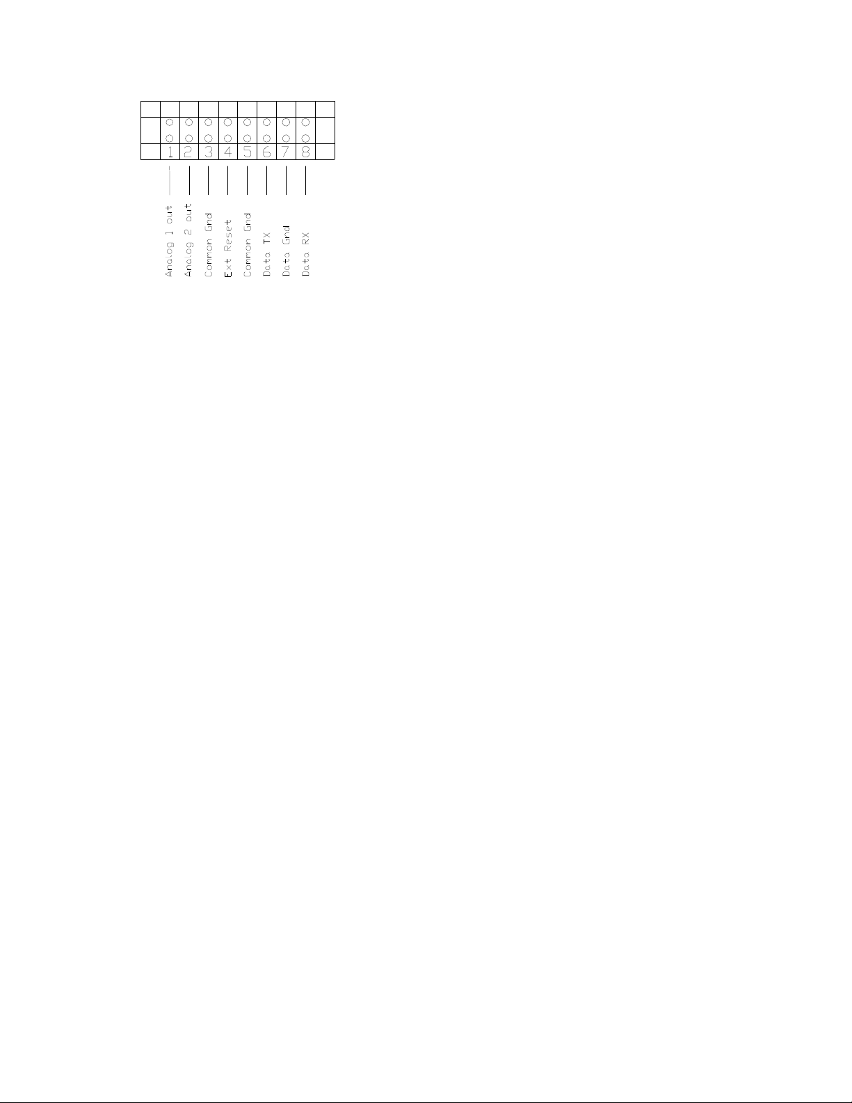
Figure 9.
0–10 Volt Analog Outputs: The IR-SNIFMCD monitor provides two 0–10 volt analog
outputs. Analog 1 provides a signal
proportional to 0-1000 ppm indicating the
current ppm level. Analog 2 provides a
signal proportional to the area being
measured, based on 0-10 volts proportional
to 0 to 32 areas. For simple installations
this signal will not normally be used. For
applications where the IR-SNIF-MCD is
installed inside a mechanical room, the
analog 1 signal can be used to drive an
optional remote analog display at the
entrance to the room. This signal could be
used to provide an analog input to building
management systems for remote
monitoring of the ppm level and for trending
of levels. This signal should NOT be used
as a replacement for discrete alarm relay
connections to a BMS. Analog output
connections are as follows:
1. Use twisted pair wire for analog 1
connection, or four conductor twisted
wire for both analog 1 and analog 2.
Typical low voltage solid conductor
wire is suitable for this signal.
Shielded cable is preferred, but not
always required.
2. Route twisted pair wire into the
monitor and along the wire harness
from the back-plate to the TB3 on
the back-plate. Secure the twisted
pair periodically to the wire harness
using tie wraps.
3. Connect the appropriate wires to
TB3-1, analog 1 plus, and TB3-3,
reference ground.
4. Connect the appropriate wires to
TB3-2, analog 2 plus, and TB3-3,
reference ground.
4–20 mA Optional Analog Outputs: The
IR-SNIF-MCD monitor provides a optional
4–20 mA analog outputs in place of the
standard 0-10 volt analog outputs. To
identify whether a monitor has 4-20 mA
analog output installed, examine the control
board installed on the door of the monitor.
Locate the chip sockets labeled U13 and
U14. U13 and U14 are located in the
center of the board, approximately 3.5
inches and 2 inches from the bottom of the
board. If the monitor is configured for the
standard 0-10 volt analog outputs, the
sockets will be empty. If configured for 420 mA outputs, the sockets will have 4-20
mA drive chips installed. Connection to the
4-20 mA outputs is the same as for 0-10
volt outputs.
RS-485 Optional Serial Output: The IRSNIF-MCD monitor provides an optional
RS-485 interface for use with ACC 070
SenTech COMM LINK PC to Refrigerant
Monitor Interface, or ACC 065 SenTech
Remote Control Panel Interface.
This interface provides the ability to display
the refrigerant levels in each area and
modify setpoints via a pc based interface.
Used in conjunction with the ACC 070
COMM LINK, the interface allows for
complete remote monitoring of multiple
refrigerant monitors in the same facility.
This interface also provides the ability to
display the refrigerant levels in each area
and modify setpoints via a digital remote
16

control interface. Used in conjunction with
the ACC 065 Remote Control Panel
Interface, the RS-485 interface allows for
complete remote control and monitoring of
multiple refrigerant monitors in the same
facility.
RS-485 digital connections are as follows:
1. Use twisted wire for RS-485
connection, either twisted triple wire,
or four conductor twisted wire.
Shielded cable is preferred, but not
always required.
2. Route twisted pair wire into the
monitor and along the wire harness
from the back-plate to the TB3 on
the back-plate. Secure the twisted
wire periodically to the wire harness
using tie wraps.
3. Connect the transmit conductor to
TB3-6.
4. Connect the receive conductor to
TB3-8.
5. If twisted triple wire is used, connect
the remaining wire to TB3-7,
reference or shield ground.
6. If two twisted pairs are used, connect
one conductor from each pair to
TB3-7, reference ground or shield.
Custom Control Inputs/Outputs: The IRSNIF-MCD monitor has the capability to be
programmed for additional optional inputs
or outputs. The control circuit in the
monitor is versatile and can accommodate
additional analog or discrete measurement
and control signals. This circuit also has
the capability to provide additional discrete
control signals. Please contact SenTech
Corporation technical support to determine
whether specific requirements can be
provided.
17
STARTUP and PROGRAMMING
Press ENT for Menu
www.sentechcorp.com
www.sentechcorp.com
Copyright (c) 2004
Apply Power
Caution: Before applying power,
double-check all wiring.
Once the installation has been completed,
and wiring has been checked, close the
door to the monitor and apply power. The
unit will go through its normal startup
checks and warm-up procedure. It is
important that the door remain closed to
ensure a proper operation.
Initial Screens
If the IR-SNIF-MCD has never been
programmed, it will access default memory
settings and display the following screen:
Once the defaults have been stored, or if
the monitor has been previously
programmed, the following screen will be
displayed. Since the monitor is factory
calibrated, and factory programmed during
quality control, it should display this screen
on initial application of power.
Following memory initialization, the monitor
will display the copyright screen.
RESETTING DEFAULTS
restore from memory
The monitor will next display two Contact
and Model Information screens. (Note:
these screens can be accessed anytime
during normal operation by pressing the “*”
key.)
Following display of the contact and model
information screens, the IR-SNIF-MCD will
restore any alarms that have been saved
into memory. The corresponding lights and
relays will be energized. Any external
alarms, exhaust fans or building
management system connections will be
activated. The monitor will then display the
following optics warm-up screen.
SenTech Corporation
IR-SNIF-MCD16
Gas Monitor
SenTech
Corporation
Phone 1-888-248-1988
Model IR-SNIF-MCD
Version 4261
Option Code 0
Optics Warm up
Timer 540 12:00
18

On completion of the warm-up, the monitor
Press ENT for Menu
Press ENT for Menu
4)…Setup ABORT
Code : 0
ACCESS DENIED
will enter Auto zero mode and begin normal
operation.
If during the startup, a fault condition is
detected, follow the instructions on the
screen, and refer to the trouble-shooting
section of this manual.
Normal Operation
During normal operation, the monitor will
display one of two basic screens. First, it
will measure the fresh air reference and
display the Auto Zero screen. Then it will
measure the sample air and display the
Auto Sample screen.
The Auto Zero measurement will take
approximately 25 seconds, and will be
performed approximately every 3 minutes.
If the monitor senses refrigerant in the
sample air, it will lengthen the Auto Zero
time to approximately 45 seconds.
** Auto Zero**
Timer 24 12:00
The Auto Sample measurement will be
taken for between 1 minute and 3 minutes,
depending on the tube length programmed
into the monitor. This screen will display
the ppm reading, the time of day and the
refrigerant programmed for the sample
area.
Auto Sample AREA 1
PPM 0 12:00
R-134A
Initial Programming
Once the IR-SNIF-MCD has completed
warm-up, and entered Auto Zero, it can be
programmed. While in Auto Zero or Auto
Sample modes, press the “ENT” key to
access the main menu.
1)…Status
2)…Rezero
3)…Manual
Key selections 1, 2 and 3 are used to
display current alarms, manually initiate
Auto Zero and enter the Manual Override
mode. These functions are discussed in
Appendix A of manual.
To program the monitor, press the “4” key
to enter Setup. The monitor will require a
password to access the setup screens.
There are five setup passwords: 111, 222,
333, 444, 999. The first four passwords
can be changed to user-defined codes.
999 cannot be changed.
* SenTech Monitor *
ENTER PASSWORD
Followed By ENT
If an incorrect password is entered, the
fourth line of the screen will change to
“Access Denied” and the monitor will return
to normal operation.
* SenTech Monitor *
ENTER PASSWORD
Followed By ENT
19

When the correct password has been
4)…Contact ABORT
ABORT
->
entered the monitor will display the setup
screen.
1)…IR Setup
2)…N/A
3)…System Setup
Press the “3” key to enter System Setup.
System setup consists of two screens that
allow the user to change passwords,
change system flags, test the alarm circuits
and set the time and date. The user can
toggle from one screen to the other by
using the left and right arrow keys.
1)…Change Code
2)…System Flags
3)…Alarm Test
4)…Date/Time
5)…Trending
Key selections 1, 3 and 5 are used to:
change passwords, test the alarm relays
and program data trending. Refer to
Appendix A of manual for instructions to
change passwords. The alarm test function
is described in the Final Test section of this
manual. Refer to Appendix A of the manual
for instructions to program trending.
Press the “2” to enter the System Flags
screens. The system flag screen will
display information for five settings,
displayed on two screens. Press the ENT
key to move the cursor from one line to the
next, and press the left arrow key to move
from one line to the previous.
The autozero flag can be used to limit the
frequency of autozero cycles. It can be set
between 0 and 100. If a 0 is entered, the
monitor will enter an autozero cycle after
every area is sampled (this is the normal
default configuration). Increasing this
number will allow the monitor to skip the
autozero cycle if the raw measurement from
the IR-Bench has not changed significantly.
That is, if the raw signal varies by less than
plus or minus 10 millivolts, and the autozero
flag is set to 10, the monitor will not perform
an autozero cycle. NOTE: This is
effectively reducing the extreme low-level
sensitivity of the monitor. If this feature is
desired, set this flag by increasing it in
small steps, 1 or 2 digits at a time, until the
monitor stops autozeroing after every zone.
The password flag can be set to either 0 or
1. If a 1 is entered, the monitor will require
the user to enter a password to perform any
functions of the monitor. This feature is
useful if the monitor is installed in a public
area, and controlled access to the monitor
is needed. This flag is set to 0 by default.
Press the “ENT” to move the cursor to the
horn relay flag. The horn relay flag can be
set to 0, 1, 2 or 3. This flag changes the
function of the horn relay to control an
audible alarm. With the flag set to the 0,
the horn relay will be disabled. The monitor
can be programmed to allow the horn relay
to be de-energized while the monitor is still
in alarm. This feature is useful when the
user is troubleshooting an alarm, and wants
to work in silence. Set the horn relay flag to
1 to activate the horn relay when the
monitor is in LOW alarm. Set the horn
relay flag to 2 to activate the horn relay
when the monitor is in MAIN alarm. Set the
horn relay flag to 3 to activate the horn
relay when the monitor is in HIGH alarm.
This flag is set to 2 by default.
20

The unit number flag is used to identify the
AUTOZERO FLAG 0
UNIT NUMBER FLAG 1
TWA REFRESH 5
LATCH FLAG 0
monitor on a RS-485 network, if that option
has been purchased. This flag is set to 1
by default.
PASSWORD FLAG 0
HORN RELAY FLAG 0
-
Press the “ENT” key to move the cursor to
the next entry. When all entries have been
viewed, press the “ENT” key again to
display the second system flag screen
SLOPE FLAG 50 TWA ALARM 0
FULL SCALE 1000
The slope flag is used for circumstances
where an individual zone might be exposed
to large levels of refrigerant. This flag will
hold the monitor in its current mode,
whether it be autosample or autozero, if the
raw measurement has not leveled off to a
constant measurement. For instance, after
an extremely large level of refrigerant has
been measured, the monitor might run in
autozero longer than expected if the
measured level is still falling. Set this flag
to the factory default of 50 if no large levels
are expected. Set this flag lower if large
levels are expected.
Press the “ENT” key to move the cursor to
the TWA ALARM flag. This flag is reserved
for future implementation of TWA
measurement. This flag should be left at
the factory default of 0.
Press the “ENT” key to move the cursor to
the FULL SCALE flag. This flag is used to
adjust the full scale measurement for the
analog output. The factory default is 1000,
meaning that the 0-10 volt analog output
corresponds to 0-1000 ppm. This flag
should be left at the factory default unless a
custom measurement range has been
implemented in the monitor. Consult
factory technical support for further
information if needed.
Press the “ENT” key to move the cursor to
the TWA refresh flag. This flag is used to
save peak ppm measurements if Trending
is not implemented. A TWA refresh rate of
5 minutes corresponds to a theoretical tenhour time weighted average (5 minute
refresh rate times 120 saved data points
yields ten-hour average). As with the TWA
ALARM flag, this feature is not yet
implemented.
Press the “ENT” key to move the cursor to
the next entry. When all entries have been
viewed, press the “ENT” key again to
display the third system flag screen.
LOW DELAY 0 MAIN DELAY 0
HIGH DELAY 0
The DELAY FLAGS are used to implement
an additional time delay, in minutes before
energizing the respective alarm relays.
This time delay is similar to the LEAK
WAIT, except that the user is able to create
a time definite delay, rather than the ppm
level defined LEAK WAIT delay. The
factory default setting is 0 for each delay.
Press the “ENT” key to move the cursor to
the next entry. Once the DELAY entries
have been viewed, press the “ENT” key to
move the cursor to the LATCH FLAG. The
LATCH FLAG is used to determine if the
21

LOW and MAIN alarms are self-resetting or
ABORT
->
Enter Minute: 35
4)…Contact ABORT
<- ABORT
Year (00
-
99): 04
are latched. If the LATCH FLAG is set to 0,
the alarms will function as a conventional
latching alarm. If the LATCH Flag is set to
1, the LOW and MAIN alarms will function
as self-resetting alarms. The HIGH alarm
will always be a latching alarm.
NOTE: The ASHRAE-15 standard specifies
that an alarm relay must be latched, but
that if more than one alarm level is
provided, the additional alarms may be selfresetting. Care must be used when
implementing this feature, as the alarm
level that corresponds to the ASHRAE-15
required alarm MUST be a latching alarm.
If there are any questions regarding the
correct implementation of this feature, call
SenTech technical support.
Press the “ENT” key to move the cursor to
the next entry. When all entries have been
viewed, press the “ENT” key again to return
to the previous menu. The monitor should
again display the system setup menu.
1)…Change Code
2)…System Flags
3)…Alarm Test
Press the right arrow ”->” key to access the
second system setup screen.
4)…Date/Time
5)…Trending
Press the “4” key to set the date and time.
The program time/date screens allows the
user to set the day of the week, hour,
minute, month, day, and year for the real
time clock (RTC) in the controller. Entering
information, or pressing the “ENT” key will
move the cursor down to the next entry.
Program Time/Date
Day (Sunday = 0): 3
Enter Hr (0-23): 12
Note that the RTC operates on a 24-hour
clock. For example to enter 2 PM, enter the
hour as 14, rather than 2.
Program Time/Date
Month (1-12): 10
Day (0-31): 27
When the date and time have been
entered, press the “ENT” key to return to
the system setup screen.
When the date, time and system flags have
been set correctly, press the “ABORT” key
to return to the Setup menu.
1)…IR Setup
2)…N/A
3)…System Setup
As of January 1, 2003 the standard IR-SNIF
monitor is capable of detecting and
responding to the following list of
refrigerants.
R-11, R-12, R-13, R-22, R-113, R-114, R123, R-134A, R-401A, R-401B, R-402BHP81, R-404A-HP-62, R-407A-AC9000, R408A, R-409A, R-410A-AZ20, R-500, R502, R-503, R-507-AZ50
This list changes over time, so it is
recommended that the operator review the
22

Gas Code screens for a complete list of
2 – Enable ABORT
Alarm Low 25
Alarm Main 50
Alarm High 500
ENT or ABORT
AREA 1 <
ENT or ABORT
AREA 1
ENT or ABORT
AREA 1
ENT or ABORT
gasses a given monitor is capable of
monitoring.
Press the “1” key to enter IR Setup. The
setup screens allow the user to program the
refrigerant to be monitored, the distance of
the tube used for the sample, and the Low,
Main and High alarm thresholds for each
sample area. Note that different settings
can be programmed for each area, and that
every area must be programmed for proper
operation. The first setup screen will
display 1 to enter parameters, or 2 to
enable or disable sample areas.
Program Setpoints
For Each AREA
1 – Setup
Press the “1” key to setup parameters for
each area.
R-134A 8
Distance 250
- ->
Press the left or right arrow keys to change
from one sample area screen to another.
Press the “ENT” key to move the arrow
cursor from line one to line two.
R-134A 8 <- ->
Distance 250
Press the left or right arrow keys to change
from one gas type to another. The gasses
are organized in numerical order, with
refrigerants first, and fire suppression
agents or blowing agents following
refrigerants. Once the appropriate gas is
displayed, press the “ENT” key to move the
cursor from line two to line three.
R-134A 8
Distance 250 -
Enter the tube length, in feet, if the tube
length is greater than 100 feet. If the tube
is shorter than 100 feet, leave the setting at
the factory default of 100. When the
distance has been entered, press the “ENT”
key to display the second sample setup
screen.
-
Unless specified otherwise, SenTech
Corporation recommends the following
alarm settings for all refrigerants except R-
123:
Low = 25 ppm
Main = 50 ppm
High = 500 ppm
Unless specified otherwise, SenTech
Corporation recommends the following
alarm settings for R-123:
Low = 25 ppm
Main = 50 ppm
High = 150 ppm
These settings are based on the current
acceptable exposure levels and short-term
exposure levels on a time weighted
average for refrigerants. SenTech
recommends that under no circumstances
should a refrigerant monitor be set above
23

the short-term exposure level. These are
2 – Enable ABORT
AREA 1 <
ENT or ABORT
AREA 1
ENT o
r ABORT
recommended settings only. Refer to local
codes and regulations for the appropriate
settings for a given application.
Once the gas code, distance and alarm
settings have been entered, press the
“ABORT” key to return to the Setup Menu.
Program Setpoints
For Each AREA
1 – Setup
If any of the available sample ports are not
used, press the “2” key to enter the
enable/disable screen.
Status 1
1-Enable 0-Bypass
- ->
Press the left or right arrow keys to change
from one sample area screen to another.
Press the “ENT” key to move the arrow
cursor from line one to line two.
Status 1 1-Enable 0-Bypass
To bypass, or disable a sample area,
change the “1” to a “0” and press the “ENT”
key. Once the appropriate areas have
been disabled, press the “ABORT” key to
return to the IR-Setup screen, again to
return to the Setup Screen, and again to
return to normal operation. The monitor
should enter Auto zero mode.
24

Press Key To Test
RESET To Clear
FINAL TESTS
At this point, the system should have all
settings programmed and it should be
monitoring in the Auto sample mode. There
are four stages to the final checks: Correct
Monitor Sequencing, Correct Integration
with External devices, Response to
Refrigerant and End-to-End System Test
Monitor Sequencing
Watch the unit as it measures the sample
area. Make certain that it periodically
switches from the Auto sample mode to the
Auto zero mode, and back again. Make a
note of the ppm reading in the sample area.
The reading should be zero. It may
periodically measure a transient level of
between 0 and 10 ppm, but it should never
stay above 10 ppm if no leak is present. If
the reading is consistently higher than 10
ppm, or if it enters alarm, it is likely there is
a leak present. A high reading may also
result from the recent use of a chlorinated
cleaning agent. Many industrial degreasers
use chlorine based organic compounds.
Examples are trichloroethylene, or
perchloroethylene. If there is no leak and
there are no other sources of halogen
vapors in the room, contact SenTech
technical support.
Integration with External Devices
Once a monitor has been connected to
external alarms, fans and building systems,
integration can be checked using the Alarm
test function of the monitor. The Alarm test
screen is found in the System Setup menus
described previously in the start up and
programming section of this manual.
The setup menu is accessed by pressing
the “ENT” key. Press the “4” key to enter
setup, followed by the password “999”.
From the setup menu, press the “3” key to
enter system setup. From the System
setup menu, press the “3” key to enter the
alarm test screen.
Key selections 1, 2, and 3 are used to
energize the Low, Main and High alarm
relays respectively. Key selection 4 will
initiate a cycle that turns on the low relay,
then the main relay, then the high relay,
until all three relays are energized. If any
relay has been energized, the fourth line of
the display will change to instruct the user
to press the “RESET” key to de-energize
the relays.
With the alarm relays energized, confirm
that the monitor is correctly integrated into
the building systems. Once this test has
been completed, press the “ABORT” key.
The monitor will restore any alarms that
existed prior to entering this test mode, and
will return to the system setup screen.
Press the “ABORT” key again to return to
normal operation.
Alarm Test
1)…Low 2)…Main
3)…HIGH 4)…All
Alarm Test
1)…Low 2)…Main
3)…HIGH 4)…All
25

Response to Refrigerant
After checking the alarms, the next step is
to check for a proper response to the
presence of a refrigerant. This will be done
by preparing a sample of refrigerant for
testing, and then presenting it to the system
to make certain it measures refrigerant. It
is suggested the following steps are
completely reviewed before starting. This
test is best done after the monitor has been
running normally for an hour or two.
Step 1: Remove the inlet tubing from the
sample inlet.
Step 2: Prepare a refrigerant sample.
Note that refrigerants can be
Chlorofluorcarbons (CFC's),
Hydrochlorofluorocarbons (HCFC's) or
Hydrofluorocarbons (HFC's). HFC's are the
only refrigerants considered to be truly
"Ozone Friendly". Because of this,
SenTech Corporation recommends use of
an HFC, such as R134A for field-testing of
the IR-SNIF series of monitors. Any fieldtesting of a refrigerant monitor, by its very
nature, will release an amount of refrigerant
into the environment through the exhaust
port of the monitor.
Caution: Follow all national and
local codes for safe handling of
refrigerants.
Because the IR-SNIF-MCD is factory
calibrated, and no field calibration is
necessary, the refrigerant sample is not
required to be of a known level. A
calibrated "test gas" kit is available from
SenTech Corporation, should the user
desire to perform the following tests with a
sample of known PPM level. The following
paragraphs describe a procedure for
preparation of a refrigerant sample using
pure refrigerant.
Three items are needed to prepare a
sample:
A Refrigerant
A Container
A short piece of 1/4" Tube.
The Refrigerant should be available on-site,
but if not, R-134A is readily available at
local stores. Note that many local office
supply stores sell a 'pressurized air duster'.
Often, this product is simply pressurized
Tetrafluoroethane, or R-134A. This is a
cost effective, readily available source of
pure test gas, as long as the contents have
been verified to be Tetrafluoroethane.
The sample container may also be
available on-site. Suitable sample
containers range from lab quality sealed
bags with twist valves to a simple plastic
bag or even an open top jar or can. The
container should be at least 4 liters, or
about a gallon. The container should be
able to be loosely closed, e.g. twisting a
plastic bag, or closing a lid.
The 1/4 inch tubing should be long enough
to connect to the sample inlet and extend
into the bottom of the sample container.
Because refrigerants are heavier than air,
pulling the sample from the bottom of the
container will ensure introduction of the
refrigerant into the selected zone.
a) Gaseous Refrigerants: Insert a
refrigerant fill hose into the container
opening. Crack the valve for a second or
less so that a small squirt of refrigerant
enters. Keep in mind that the monitor reads
in PPM (parts per million) and a tiny amount
of gas will make a relatively high
concentration sample. Pull out the hose,
and loosely close the container.
26

b) Liquid Refrigerants: Open the container
slightly and put in a few drops of liquid
refrigerant. Loosely close the container and
allow time for the refrigerant to gasify. A
bag will expand some as the liquid
evaporates.
Caution: Do not close a rigid
sample container tightly, because
refrigerants expand and can
create pressure. Do not allow
pressure to build up in the sample
container.
Step 3: Manual measurement of sample.
Switch the monitor to manual override.
Manual Override is accessed by pressing
the "ENT" (enter) key on the front panel
display of the monitor. Press the "3" key to
enter Manual Override. Place the 1/4 inch
tube into the sample container and connect
it to the sample inlet to simulate a
concentration of refrigerant in the air.
Caution: Never connect a
pressurized refrigerant bottle
directly to the monitor. The unit is
designed to operate only at
atmospheric pressure. Doing so
can damage the unit.
After approximately 5 seconds, the PPM
reading should start to rise. Within 30 to 45
seconds, the PPM level should level off. A
sample prepared as described in step 2
should easily contain more than 150 PPM.
If the PPM reading does not rise above the
highest alarm setting in the monitor, repeat
the sample preparation procedure with a
larger amount of refrigerant. Readings of
150 or higher indicate a successful test of
the monitor's ability to sense refrigerant.
Disconnect the sample from the monitor
and save for the next step. The sample
container should now have a measured
concentration of refrigerant greater than the
highest alarm level. This will be used to
test the end-to-end performance of the
system in the next step.
Once the sample tube has been
disconnected from the monitor, the
readings should fall slowly down to at or
near zero PPM. When the PPM level
reaches near zero, press the "ENT" (enter)
key to exit Manual Override and return to
normal operation.
End-to-End System Test
After manually verifying the operation of the
monitor, and obtaining (creating) a sample
known to have a PPM level higher than the
highest alarm, the next step is to perform
an end-to-end test of the system. This test
will verify that the monitor will correctly
trigger alarms and the external devices
connected. This will be done by connecting
the sample of refrigerant from the previous
test to the sample inlet and observing the
alarms. This test is best done after the
monitor has run through at least two
complete auto sample and auto zero
cycles.
After approximately 5 seconds, the PPM
reading should start to rise. When the
monitor exceeds the alarm threshold, it will
switch to "Leak Wait" mode. This mode
ensures the presence of a leak before
triggering an alarm. The leak wait period
can be as short as 7 seconds and as long
as 3 minutes. Note: The more the
reading exceeds the alarm trip point, the
shorter the time to enter alarm. The
system should progress from Low alarm,
through Main alarm and into High alarm.
Note: If the monitor exceeds high alarm
while in leak wait, it will appear to trigger
Main alarm and High alarm at the same
time. This is normal, correct operation.
27

When a relay is programmed for an audible
alarm and energizes, the external horn
should sound (if so equipped) and the
bottom line of the display should change to
"RESET to Silence". This instructs the
operator to push the "RESET" key to
silence the Horn.
If the Horn has been silenced, the fourth
line of the display should change to
"RESET to Clr Alarms". This instructs the
operator to clear the alarms.
Remove the gas sample from the inlet and
wait until the PPM reading drops back to
normal. Push the "RESET" button. The
System should clear the alarms and be
back in normal Automatic operation.
Reconnect the sample inlet tube and
dispose of the gas sample in an appropriate
manner.
Documentation
Fill out the CTS/Warranty form completely
and return it to SenTech in the envelope
provided. This is an important step to
establish warranty. Please use this
opportunity to make any suggestions for
improvements.
If you are part of the user organization,
store this manual in a safe place. If you are
an installing contractor, please turn over the
manual to the user.
If you need any additional manuals, call
SenTech and we will be pleased to provide
them at no charge (make a note of the unit
serial number when requesting a manual).
Installation and Operation Manuals for
every Monitor ever produced by SenTech
Corporation are available at the SenTech
website:
www.sentechcorp.com
Basic installation and start-up is now
complete. The unit should be on line and
monitoring.
The remainder of this manual includes
further information on operational
characteristics, programming, preventive
maintenance, troubleshooting, parts lists,
and a detailed wiring diagram.
28

PREVENTIVE MAINTENANCE & REPAIR
Preventive Maintenance
The recommended periodic preventative
maintenance is as follows:
Perform Quarterly Filter Inspection and
replace as necessary.
Perform Quarterly Performance Verification.
Filter Inspection and Replacement
Coarse Filters (Tube End Filters) are
located in each sample zone and fresh air
zone on the ends of the 1/4 inch tubes.
The Coarse Filters are sintered brass or
bronze, and will naturally discolor to a dark
bronze color. Inspect the filter for obvious
clogging or build up of dust. Replace,
rather than clean the filters.
5 Micron Filter is located inside the
monitor, inside a clear moisture separator.
The 5 micron filter should be ‘paper white’,
and will turn gray, or off color when dirty.
Replace, rather than clean this filter.
Quarterly Performance Check: Once per
quarter, perform the End-to-End system
test described in the Final Checks
Procedure on page 12.
Commonly Ordered Parts
P/N Description
410144 Filter,
Coarse Tube
410162 Filter,
5 Micron
410136-GRAY Orifice, .016
410224 Diaphragm
Pump
Monitor Repair
Most monitor repairs can be performed in
the field by the typical service technician.
Refer to the Troubleshooting Guide found
at the end of this manual for assistance.
Additionally, SenTech Corporation provides
telephone technical support for all SenTech
refrigerant monitors. If assistance is
needed, call 888-248-1988 (317-248-1988
internationally).
Should a repair be beyond the normal
scope of field service, contact SenTech
Corporation for a Return Authorization
number for factory repair.
29

APPENDIX A: Programming and Operator Interface
www.sentechcorp.com
www.sentechcorp.com
Copyright (c) 2003
Press ENT for Menu
Summary
The operator interface is composed of three
sets of screens:
START-UP SCREENS - Displayed when
power is applied to the system.
OPERATIONAL SCREENS - Displayed for
the multiple gas monitoring modes.
MENU SCREENS - Screens used to
change the operational mode of the
monitor, set the configuration of the
refrigerant monitoring zones and change
system parameters for the monitor.
Start-up Screens
When power is applied to the system, it will
step through a series of start-up screens.
Copyright: The Copyright screen will be
displayed on completion memory
initialization.
RESETTING DEFAULTS
restore from memory
SenTech Corporation
IR-SNIF-MCD16
Gas Monitor
Contact Screens: The Contact Screens
display the company name, phone number
and website. After a short pause, a second
screen is displayed to identify the Model,
Version and Options installed in the
software of the monitor.
Phone 1-888-248-1988
SenTech
Corporation
Model IR-SNIF-MCD16
Version 3017
Option Code 0
Optics Warm-Up: The Optics Warm-Up
Screen is displayed while the monitor is
stabilizing internal temperature. Currently
this is set at about 9 minutes.
Optics Warmup
Timer 540 12:00
Operational Screens
When the monitor completes Start-Up and
Optics Warmup, it will enter Auto zero, and
then proceed to measure in Auto sample
mode. Under normal circumstances the
monitor will cycle from Auto sample to Auto
zero, and back to Auto sample. If an alarm
condition is detected the monitor will enter
Leak Wait mode to ensure a leak is
detected. If the operator manually
overrides the auto sample operation, the
monitor will display Manual Override until
the operator exits manual operation or the
30

monitor time outs and returns to normal
Press ENT for Menu
Press ENT for Menu
Press ENT for Menu
Press ENT for Menu
operation.
Auto zero: Auto zero measures the fresh
air (refrigerant free) zone between each
zone. Auto zero takes approximately 24
seconds under normal conditions. If the
monitor senses a high concentration of
refrigerant, the Auto zero measurement
time is extended to approximately 45
seconds.
** Auto Zero**
Timer 24 12:00
Auto Sample: Auto sample mode is the
normal measurement mode of the monitor.
It displays the PPM level beings measured,
the refrigerant and the current time. If the
Horn relay has been energized, the fourth
line will instruct the operator to press the
"RESET" key to silence the horn. If the
monitor is in alarm, the fourth line will
instruct the operator to press the reset key
to clear alarms.
Auto Sample AREA 1
PPM 0 12:00
R-134A
Leak Wait: When the monitor is in Auto
sample mode and first senses a change in
PPM, it enters Leak Wait mode. This
ensures the monitor truly detects a leak
before activating the Low Alarm relay and
the Main Alarm relay. The length of the
wait period depends upon the difference
between the concentration level and the
alarm trip point. The larger the difference,
the shorter the wait time. If the
concentration falls below the alarm trip
point, the system will determine that it was
a transient, and return to normal operation.
LEAK WAIT AREA 1
PPM 0 12:00
R-134A
Fault Mode: When the monitor detects a
fault condition, it will enter fault mode. The
Main relay will energize and "Trouble
Alarm" will be displayed in the third line of
the display.
Auto Sample AREA 1
PPM 0 12:00
Trouble Alarm
Alarm Modes: When the monitor has
sensed concentrations above the alarm trip
points, the associated relays will be
energized. The Low, Main and High relays
will be energized if the measured ppm level
has exceeded the corresponding alarm
levels. The Horn relay will be energized
depending on its programming. The
monitor can be set up to energize the Horn
relay when the Low alarm is activated, the
Main alarm is activated or the High alarm is
activated. This is programmed via the
System Setup menus described later in this
document.
If an alarm is activated, the fourth line in the
operational screens will change to instruct
the operator how to clear the alarm. When
the "RESET" is pressed, the monitor will
switch directly to the Alarm Status screen
described later in this appendix.
If the monitor has also energized the Horn
relay, it can be silenced by pressing the
"RESET" key. The fourth line in the
31

operational screens will change to instruct
RESET to Silence
RESET to Silence
4)…Setup ABORT
<- RESET or ABORT
->
ABORT
the operator how to silence the Horn.
When the alarm condition is cleared, the
Horn is enabled and will be activated
should another alarm occur.
Clear Alarm:
Auto Sample AREA 1
PPM 0 12:00
R-134A
Silence Horn:
Auto Sample AREA 1
PPM 0 12:00
R-134A
Manual Override: Manual Override mode
is useful to temporarily measure without
processing alarms. It displays the ppm
level, the refrigerant and the current time.
Alarm processing is suspended during
Manual Override. Manual Override mode is
entered by via the menus described later in
this document.
Menu Screens
The Menu Screens can be accessed from
any Operational Screen by pressing the
"ENT" or enter key. In the first menu, the
operator is given the choice to review Zone
Alarms, manually perform an Auto zero,
enter Manual Override mode or enter
Setup.
1)…Status
2)…Rezero
3)…Manual
Status: The Status Screen is accessed by
pressing the "1" key. The status screen will
allow the operator to review alarms and to
review trend data, if trending is enabled on
the monitor.
1)…Alarms
2)…Trending
If trending is not enabled, choice 2)
trending, will not be displayed.
Alarm Status: The alarm status screen is
accessed by pressing the “1” key. If any
zones are in alarm, the operator will have
access to a series of screens formatted to
show the alarm level, the peak ppm, and
the time and date of the alarm. Additional
alarm screens can be accessed by pressing
the left and right arrow keys. If there are no
alarms to display, or the last alarm has
displayed, "No More Alarms". If the
"RESET" or "ABORT" keys are pressed, the
monitor will exit and return to normal
operation.
Alarm Status
AREA 1 LOW PK 26
3/12/03 12:00
Once all of the measurement alarms have
been displayed, the Monitor will check for
Trouble Alarms. Trouble Alarms will be
generated if the monitor senses a fault in
the Infrared Bench (sensor), a fault in the
remote reset connection, a calibration fault
and a flow related failure.
IR Bench Fault: The Bench Voltage trouble
alarm will be displayed if the monitor
senses a fault in the Infrared Sensor.
32

<- RESET or ABORT
->
<- RESET or ABORT
->
<- RESET or ABORT
->
Press ENT for Menu
<- RESET or ABORT
->
Change Zone
<- ENT or ABORT
->
Trouble Alarm
Bench Voltage
Call Factory
Remote Reset Fault: The Remote reset
trouble alarm will be displayed if the remote
reset connection detects a shorted circuit.
This is helpful to prevent malfunctions in the
operation of the monitor caused by external
connections.
Trouble Alarm
Remote Reset
Call Factory
The monitor will also generate a trouble
alarm is it has never been calibrated, or if it
has had a control failure that erased the
calibration settings in read only memory.
Trouble Alarm
Monitor Is Not
Calibrated
The Pump Failure Possible trouble alarm
will be displayed if the monitor detects a
flow failure.
Trouble Alarm
Pump Failure
Possible
Press the “RESET” or “ABORT” keys to
return the monitor to normal operation.
Trend Status: The Trending screens can
be accessed by pressing the “2” key while
the Status screen is displayed. Note: the
trending screen will display two lines of
information that is twenty lines long, and up
to 120 columns wide. This feature is best
used in conjunction with the ACC 070
Comm Link and a windows based PC to
view and track trend information.
Display Trend Data
Use Arrows to Change
Time, Use ENT to
After a pause, the monitor will display trend
information, showing date, time and the first
two area information.
10/28 12:05
AREA 1 0 ppm
AREA 2 0 ppm
Press the ENT key to display other areas
for the same time. Press the left arrow and
right arrow to display trend information for
different times. Press the ABORT Key to
return to normal operation.
Rezero: The monitor can be switched into
Auto zero Mode manually by pressing the
"2" key. On completion of the manually
initiated Auto zero, the unit will return to
normal operation.
** Auto Zero**
Timer 24 12:00
Manual Override: The monitor can be
switched into Manual Override mode
manually by pressing the "3" key. The unit
will return to normal operation if the “ENT”
(enter) key is pressed, or after
33

approximately 15 minutes, whichever
Press ENT for Menu
Code : 0
4)…Contact ABORT
2 – Enable ABORT
AREA 1 <
ENT or ABORT
AREA 1
ENT or ABORT
comes first.
Manual Override 1
PPM 0 12:00
R-134A
Setup: The Setup Menus are accessed by
pressing the "4" key. The operator will be
asked to enter a password to continue into
the Setup Menus. There are five
passwords. Passwords 1 through 4 are
user definable (default passwords are
"111", "222", "333", "444"). The last
password is permanently set at "999".
* SenTech Monitor *
ENTER PASSWORD
Followed By ENT
Setup Menu: If the correct password is
entered, the unit will display the Setup
Menu Screen. From the Setup Menu, the
operator can access the refrigerant
monitoring settings (Sample Setup), the gas
code assigned to each refrigerant
programmed in the monitor, system
configurations settings and the contact
screen.
1)…IR Setup
2)…N/A
3)…System Setup
Sample Setup: Press the “1” key to enter
Sample Setup. The sample setup screens
allow the user to set the gas code for the
refrigerant to be monitored, the distance of
the tube used for the sample, and the Low,
Main and high alarm thresholds. The first
sample setup screen will display 1 to enter
parameters, or 2 to enable or disable
sample areas.
Program Setpoints
For Each AREA
1 – Setup
Press the “1” key to setup parameters for
each area.
R-134A 8
Distance 250
- ->
Press the left or right arrow keys to change
from one sample area to another. Press
the “ENT” key to move the arrow cursor
from line one to line two.
R-134A 8 <- ->
Distance 250
Press the left or right arrow keys to change
from one gas type to another. The gasses
are organized in numerical order, with
refrigerants first, and fire suppression
agents or blowing agents following
refrigerants. One the appropriate gas is
displayed, press the “ENT” key to move the
cursor from line two to line three.
As of January 1, 2003 the standard IR-SNIF
monitor is capable of detecting and
responding to the following list of
refrigerants.
R-11, R-12, R-13, R-22, R-113, R-114, R123, R-134A, R-401A, R-401B, R-402BHP81, R-404A-HP62,
34

R-407A-AC9000, R-408A, R-409A, R-
Alarm Low 25
Alarm Main
Alarm High 500
ENT or ABORT
ABORT
->
<- ABORT
View Or Change Code
A
ccess Code # 1
Access Code # 1
ENT
-
Exit
AREA 1
ENT or ABORT
410A-AZ20, R-500, R-502, R-503, R-507AZ50
This list changes over time, so it is
recommended that the operator review the
Gas Code screens for a complete list of
gasses a given monitor is capable of
monitoring.
R-134A 8
Distance 250 -
Enter the tube length, in feet, if the tube
length is greater than 100 feet. If the tube
length is shorter than 100 feet, leave the
setting at the factory default of 100. When
the distance has been entered, press the
“ENT” key to display the second sample
setup screen.
-
50
Unless specified otherwise, SenTech
Corporation recommends the following
alarm settings for all refrigerants except R-
123:
Low = 25 ppm
Main = 50 ppm
High = 500 ppm
Unless specified otherwise, SenTech
Corporation recommends the following
alarm settings for R-123:
Low = 25 ppm
Main = 50 ppm
High = 150 ppm
These settings are based on the current
acceptable exposure levels and short-term
exposure levels on a time weighted
average for refrigerants. SenTech
recommends that under no circumstances
should a refrigerant monitor be set above
the short-term exposure level. These are
recommended settings only. Refer to local
codes and regulations for the appropriate
settings for a given application.
System Setup: The System Setup menus
are accessed from the Setup menu by
pressing the "3" key. System setup
consists of two screens that allow the user
to change passwords, change system flags,
test the alarm circuits and set the time and
date. The user can toggle from one screen
to the other by using the left and right arrow
keys.
1)…Change Code
2)…System Flags
3)…Alarm Test
4)…Date/Time
5)…Trending
Change Code
The operator can change passwords 1
through 4 by pressing the "1" key. The
operator then enters the code number (1-4)
and is able to enter the new password.
Select Code # To
Code 111
35

System Flags
AUTOZERO FLAG 0
UNIT NUMBER FLAG 1
TWA REFRESH 5
Press the “2” to enter the System Flags
screens. The system flag screen will
display information for five settings,
displayed on two screens. Press the ENT
key to move the cursor from one line to the
next, and press the left arrow key to move
from one line to the previous.
Autozero Flag: The autozero flag can be
used to limit the frequency of autozero
cycles. It can be set between 0 and 100. If
a 0 is entered, the monitor will enter an
autozero cycle after every area is sampled
(this is the normal default configuration).
Increasing this number will allow the
monitor to skip the autozero cycle if the raw
measurement from the IR-Bench has not
changed significantly. That is, if the raw
signal varies by less than plus or minus 10
millivolts, and the autozero flag is set to 10,
the monitor will not perform an autozero
cycle. NOTE: This is effectively reducing
the extreme low-level sensitivity of the
monitor. If this feature is desired, set this
flag by increasing it in small steps, 1 or 2
digits at a time, until the monitor stops
autozeroing after every zone.
Password Flag: The password flag can be
set to either 0 or 1. If a 1 is entered, the
monitor will require the user to enter a
password to perform any functions of the
monitor. This feature is useful if the monitor
is installed in a public area, and controlled
access to the monitor is needed. This flag
is set to 0 by default.
Horn Relay Flag: Press the “ENT” to
move the cursor to the horn relay flag. The
horn relay flag can be set to 0, 1, 2 or 3.
This flag changes the function of the horn
relay to control an audible alarm. With the
flag set to the 0, the horn relay will be
disabled. The monitor can be programmed
to allow the horn relay to be de-energized
while the monitor is still in alarm. This
feature is useful when the user is
troubleshooting an alarm, and wants to
work in silence. Set the horn relay flag to 1
to activate the horn relay when the monitor
is in LOW alarm. Set the horn relay flag to
2 to activate the horn relay when the
monitor is in MAIN alarm. Set the horn
relay flag to 3 to activate the horn relay
when the monitor is in HIGH alarm. This
flag is set to 2 by default.
Unit Number Flag: The unit number flag is
used to identify the monitor on a RS-485
network, if that option has been purchased.
This flag is set to 1 by default.
PASSWORD FLAG 0
HORN RELAY FLAG 0
-
Press the “ENT” key to move the cursor to
the next entry. When all entries have been
viewed, press the “ENT” key again to
display the second system flag screen
SLOPE FLAG 50 TWA ALARM 0
FULL SCALE 1000
Slope Flag: The slope flag is used for
circumstances where an individual zone
might be exposed to large levels of
refrigerant. This flag will hold the monitor in
its current mode, whether it be autosample
or autozero, if the raw measurement has
not leveled off to a constant measurement.
For instance, after an extremely large level
of refrigerant has been measured, the
monitor might run in autozero longer than
expected if the measured level is still falling.
Set this flag to the factory default of 50 if no
36

large levels are expected. Set this flag
LATCH FLAG 0
lower if large levels are expected.
TWA Alarm Flag: Press the “ENT” key to
move the cursor to the TWA ALARM flag.
This flag is reserved for future
implementation of TWA measurement.
This flag should be left at the factory default
of 0.
Full Scale Flag: Press the “ENT” key to
move the cursor to the FULL SCALE flag.
This flag is used to adjust the full scale
measurement for the analog output. The
factory default is 1000, meaning that the 010 volt analog output corresponds to 01000 ppm. This flag should be left at the
factory default unless a custom
measurement range has been implemented
in the monitor. Consult factory technical
support for further information if needed.
TWA Refresh Flag: Press the “ENT” key
to move the cursor to the TWA refresh flag.
This flag is used to save peak ppm
measurements if Trending is not
implemented. A TWA refresh rate of 5
corresponds to a theoretical ten-hour time
weighted average. As with the TWA
ALARM flag, this feature is not yet
implemented.
Press the “ENT” key to move the cursor to
the next entry. When all entries have been
viewed, press the “ENT” key again to
display the third system flag screen.
LOW DELAY 0 MAIN DELAY 0
HIGH DELAY 0
Delay Flags: The DELAY FLAGS are used
to implement an additional time delay, in
minutes before energizing the respective
alarm relays. This time delay is similar to
the LEAK WAIT, except that the user is
able to create a time definite delay, rather
than the ppm level defined LEAK WAIT
delay. The factory default setting is 0 for
each delay.
Latch Flag: Press the “ENT” key to move
the cursor to the next entry. Once the
DELAY entries have been viewed, press
the “ENT” key to move the cursor to the
LATCH FLAG. The LATCH FLAG is used
to determine if the LOW and MAIN alarms
are self-resetting or are latched. If the
LATCH FLAG is set to 0, the alarms will
function as a conventional latching alarm. If
the LATCH Flag is set to 1, the LOW and
MAIN alarms will function as self-resetting
alarms. The HIGH alarm will always be a
latching alarm.
NOTE: The ASHRAE-15 standard specifies
that an alarm relay must be latched, but
that if more than one alarm level is
provided, the additional alarms may be selfresetting. Care must be used when
implementing this feature, as the alarm
level that corresponds to the ASHRAE-15
required alarm MUST be a latching alarm.
If there are any questions regarding the
correct implementation of this feature, call
SenTech technical support.
Press the “ENT” key to move the cursor to
the next entry. When all entries have been
viewed, press the “ENT” key again to return
to the previous menu. The monitor should
again display the system setup menu.
Alarm Test: The Alarm Test screen is
used to enable the installer to verify that the
monitor is correctly integrated into the
building systems.
37

Pre
ss Key To Test
RESET To Clear
Enter Minute: 35
Year (00
-
99): 04
ENT or ABORT
Alarm Test
1)…Low 2)…Main
3)…HIGH 4)…All
Key selections 1, 2, and 3 are used to
energize the Low, Main and High alarm
relays respectively. Key selection 4 will
initiate a cycle that turns on the low relay,
then the main relay, then the high relay,
until all three relays are energized. If any
relay has been energized, the fourth line of
the display will change to instruct the user
to press the “RESET” key to de-energize
the relays.
Alarm Test
1)…Low 2)…Main
3)…HIGH 4)…All
With the alarm relays energized, confirm
that the monitor is correctly integrated into
the building systems. Once this test has
been completed, press the “ABORT” key.
The monitor will restore any alarms that
existed prior to entering this test mode, and
will return to the system setup screen.
Press the “ABORT” key again to return to
normal operation.
Date/Time: The Date/Time menu is
accessed by pressing the "4" key. The
program time/date screens allows the user
to set the day of the week, hour, minute,
month, day, and year for the real time clock
(RTC) in the controller. Entering
information, or pressing the “ENT” key will
move the cursor down to the next entry.
Program Time/Date
Day (Sunday = 0): 3
Enter Hr (0-23): 12
Note that the RTC operates on a 24-hour
clock. For example to enter 2 PM, enter the
hour as 14, rather than 2.
Program Time/Date
Month (1-12): 10
Day (0-31): 27
When the date and time have been
entered, press the “ENT” key to return to
the system setup screen.
Trending: The Trending screens enable
the end user to track measured levels over
time. This feature will be helpful in isolating
low level, intermittent alarms. Trending
currently saves the peak ppm level
measured in each zone periodically at a
user defined rate and time. The trending
screens allow the user to select save rates
of once per hour, once per day, once per
week and once per month.
Program Trend Data
Trend Rate:
(<- ->) Hourly
Press the Left and Right arrow keys to
display the desired trend rate. Press the
ENT key to select the desired trend rate.
The monitor will automatically request the
appropriate time and date information.
When complete, press the ABORT key to
return to normal operation.
For Monthly trend rate, the monitor will
request:
Day of month (1-31)
Hour (0-23)
Minute (0-59)
38

For Weekly trend rate, the monitor will
request:
Day of week (0-6)
Hour (0-23)
Minute (0-59)
For Daily trend rate, the monitor will
request:
Hour (0-23)
Minute (0-59)
For Hourly trend rate, the monitor will
request:
Minute (0-59)
39

APPENDIX B: SenTech Room Volume Considerations
(English)
Normal industry practice has been to think
about refrigerant leaks in terms of pounds
of refrigerant per unit time, such as lbs/hr or
oz/yr. This is a natural and logical way of
looking at it. The system monitors the
amount of refrigerant present in the air in
parts per million (ppm) by volume or
refrigerant molecules as compared to air
molecules. In order to develop a correlation
between the leak rate in weight per unit
time and parts per million, there are a
number of items that need to be
considered. These are:
1. Room volume.
2. The weight of refrigerant per unit
volume at ambient temperature and
pressure.
3. The amount of time the refrigerant
has been leaking.
4. The rate at which fresh air enters the
room and existing air is exhausted.
5. The location of the inlet, relative to
the leak, airflow in the room and the
rate at which the refrigerant expands
to fill the room.
For a specific application, items 1 through 4
can be calculated, or estimated. Item 5 is
virtually unpredictable, therefore in all
calculations; it is assumed that the leaking
refrigerant will expand to fill the room with
an even distribution of refrigerant. This
assumption will yield safer, conservative
calculations. If the monitor sample and
reference locations have been appropriately
chosen, the monitor will see a higher
concentration than calculated from the ideal
formulas.
Formula Definitions:
ppm – refrigerant concentration
LR – leak rate in cubic feet/hour
FA – fresh air into the room in cubic
feet/hour
VOL – room volume in cubic feet
t – time in hours
R – volume of refrigerant in cubic
feet
LRmin – minimum leak rate that will
result in a given ppm
RD – refrigerant density in lbs/cubic
foot
To be able to convert between ppm and
leak rate in cubic feet/hour, the refrigerant
density must be calculated. If the molecular
weight of the refrigerant is known, the
refrigerant density can be calculated.
[MolWt(gms)/1(mole)] x [1(mole)/22.4(l)] x [1(lb)/454(g)] x
[28.32(l)/1(cuft)] x [273(K)/293(K)] = RD(lb/cuft)
Calculating for R-22, 86.48(g/mole), RD22
= .22 lb/cuft and
1/RD22 = 4.46 cuft/lb
Other densities are as follows:
R-22 RD22 = .22 lb/cuft
R-12 RD12 = .31 lb/cuft
R-11 RD11 = .36 lb/cuft
R-502 RD502 = .29 lb/cuft
R-123 RD123 = .41 lb/cuft
40

Two examples have been developed to demonstrate the conversion. Case I is for a
sealed room, with no air turnover. Case II is for a room with a known air turnover.
Case I: Sealed room 40 ft x 30 ft x 10 ft
high
1. How much R-22 (in lbs) is necessary to
cause a measurement of 25 ppm?
Given 25 ppm R-22 in the sealed room:
Volume of R-22 = parts per million / million x room
volume
R(cuft) = [25(ppm)/1,000,000] x [40 x 30 x 10](cuft)
R(cuft) = .3 cuft of R-22 in the sealed room
Given .3 cuft R-22, calculate weight in lbs:
Weight = volume(cuft) x density(lb/cuft)
Weight = R(cuft) x RD22(lb/cuft)
Weight = .3(cuft) x .22(lb/cuft)
Weight = .066 lbs
2. If the leak rate is 300 lb/yr, how long will
it take to reach 25 ppm?
Given the same refrigerant in the same
room, 25 ppm weighs .066 lbs:
Time(hr) = weight of R-22(lb) / [weight(lb)/time(yr)] x
[time(hr)/time(yr)]
Time(hr) = .066(lb) / [300(lb)/1(yr)] x [8760(hr)/1(yr)]
Time(hr) = 1.93 hrs
Case II: 40 ft x 30 ft x 10 ft high room with
fresh air makeup of 100 cfm
1. How much R-22 (in lbs/yr) is necessary
to cause a measurement of 25 ppm?
Given air turnover of 100cfm, calculate the
fresh air volume in cuft/hr:
Air flow (cuft/hr) = air flow (cfm) x [60(min)/1(hr)]
Air flow(cuft/hr) = 100cfm x 60 min/hr = 6000 cuft/hr
Given 6000 cuft/hr, calculate the leak rate
that is required to maintain a measurement
of 25 ppm:
Leak rate min (cuft/hr) = parts per million/million x fresh
volume(cuft/hr)
Leak rate min (cuft/hr) = [25(ppm)/1.000.000] x 6000(cuft/hr)
Leak rate min(cuft/hr) = .15 cuft/hr
Given .15 cuft/hr, calculate the leak rate in
lb/yr needed to reach 25 ppm:
Leak rate(lb/yr) = leak rate(cuft/hr) x density(lb/cuft) x [8760(hr) /
1(yr)]
Leak rate(lb/yr) = .15(cuft/hr) x .22(lb/cuft) x 8760(hr/yr)
Leak rate(lb/yr) = 289 lb/yr, therefore the leak rate must be
GREATER THAN 289 lb/yr.
2. If the leak rate is 500 lb/yr, how long will
it take to reach 25 ppm?
Calculate LR in cuft/hr:
LR(cuft/hr) = [leak rate(lb/yr) / density(lb/cuft)] / 8760(hr/yr)
LR(cuft/yr) = 500(lb/yr) / .22(lb/cuft) / 8760(hr/yr)
LR(cuft/yr) = .26 cuft/hr
Calculate time in hr:
Time(hr) = [Room volume(cuft)/Air flow(cuft/hr)] x ln[LR(cuft/hr) /
[LR(cuft/hr) – Leak rate min(cuft/hr)]]
Time(hr) = [12000(cuft)/6000(cuft/hr)] x ln[.26(cuft/hr)/[.26(cuft/hr).15(cuft/hr)]
Time(hr) = 2(hr) x ln[2.3636] Time(hr) = 1.72 hr
41

SenTech Room Volume Considerations
(Metric)
Normal industry practice has been to think
about refrigerant leaks in terms of pounds
of refrigerant per unit time, such as lbs/hr or
oz/yr. This is a natural and logical way of
looking at it. The system monitors the
amount of refrigerant present in the air in
parts per million (ppm) by volume or
refrigerant molecules as compared to air
molecules. In order to develop a correlation
between the leak rate in weight per unit
time and parts per million, there are a
number of items that need to be
considered. These are:
1. Room volume.
2. The weight of refrigerant per unit
volume at ambient temperature and
pressure.
3. The amount of time the refrigerant
has been leaking.
4. The rate at which fresh air enters the
room and existing air is exhausted.
5. The location of the inlet, relative to
the leak, airflow in the room and the
rate at which the refrigerant expands
to fill the room.
For a specific application, items 1 through 4
can be calculated, or estimated. Item 5 is
virtually unpredictable, therefore in all
calculations, it is assumed that the leaking
refrigerant will expand to fill the room with
an even distribution of refrigerant. This
assumption will yield safer, conservative
calculations. If the monitor sample and
reference locations have been appropriately
chosen, the monitor will see a higher
concentration than calculated from the ideal
formulas.
Formula Definitions:
ppm – refrigerant concentration
LR – leak rate in cubic meter/hour
FA – fresh air into the room in cubic
meter/hour
VOL – room volume in cubic meter
t – time in hours
R – volume of refrigerant in cubic
meter
LRmin – minimum leak rate that will
result in a given ppm
RD – refrigerant density in kg/cubic
meter
To be able to convert between ppm and
leak rate in cubic meter/hour, the refrigerant
density must be calculated. If the molecular
weight of the refrigerant is known, the
refrigerant density can be calculated.
[MolWt(gms)/1(mole)] x [1(mole)/22.4(l)] x [1(kg)/1000(g)] x
[273(K)/293(K)] = RD(kg/cubic meter)
Calculating for R-22, 86.48(g/mole), RD22
= 3.59 kg/cubic meter and
1/RD22 = .28 cubic meter/kg
Other densities are as follows:
R-22 RD22 = 3.59 kg/cubic meter
R-12 RD12 = 4.96 kg/cubic meter
R-11 RD11 = 5.76 kg/cubic meter
R-502 RD502 = 4.64 kg/cubic meter
R-123 RD123 = 6.56 kg/cubic meter
42

Two examples have been developed to demonstrate the conversion. Case I is for a
sealed room, with no air turnover. Case II is for a room with a known air turnover.
Case I: Sealed room 15 m x 10 m x 3 m
high
1. How much R-22 (in kg) is necessary to
cause a measurement of 25 ppm?
Given 25 ppm R-22 in the sealed room:
Volume of R-22 = parts per million / million x room
volume
R(cubic meter) = [25(ppm)/1,000,000] x [15 x 10 x 3](cubic meter)
R(cuft) = .01125 cubic meter of R-22 in the sealed room
Given .01125 cubic meter R-22, calculate
weight in kg:
Weight = volume(cubic meter) x density(kg/cubic meter)
Weight = R(cubic meter) x RD22(kg/cubic meter)
Weight = .01125(cubic meter) x 3.59(kg/cubic meter)
Weight = .040 kg
2. If the leak rate is 150 kg/yr, how long will
it take to reach 25 ppm?
Given the same refrigerant in the same
room, 25 ppm weighs .040 kg:
Time(hr) = weight of R-22(kg) / [weight(kg)/time(yr)] x
[time(hr)/time(yr)]
Time(hr) = .040(kg) / [150(kg)/1(yr)] x [8760(hr)/1(yr)]
Time(hr) = 2.34 hrs
Case II: 10 m x 15 m x 3 m high room with
fresh air makeup of 225 cubic meter/hr
1. How much R-22 (in kg/yr) is necessary to
Given air turnover of 225cubic meter/hr,
calculate the leak rate that is required to
maintain a measurement of 25 ppm:
Leak rate min (cubic meter/hr) = parts per million/million x fresh
volume(cubic meter/hr)
Leak rate min (cubic meter/hr) = [25(ppm)/1.000.000] x 225(cubic
meter/hr)
Leak rate min(cubic meter/hr) = .005625 cubic meter/hr
Given .005625 cubic meter/hr, calculate the
leak rate in kg/yr needed to reach 25 ppm:
Leak rate(kg/yr) = leak rate(cubic meter/hr) x density(kg/cubic
meter) x [8760(hr) / 1(yr)]
Leak rate(kg/yr) = .005625(cubic meter/hr) x 3.59(kg/cubic meter)
x 8760(hr/yr)
Leak rate(kg/yr) = 176.9 kg/yr, therefore the leak rate must be
GREATER THAN 177 kg/yr.
2. If the leak rate is 300 kg/yr, how long will
it take to reach 25 ppm?
Calculate LR in cubic meter/hr:
LR(cubic meter/hr) = [leak rate(kg/yr) / density(kg/cubic meter)] /
8760(hr/yr)
LR(cubic meter/yr) = 300(kg/yr) / 3.59(kg/cubic meter) /
8760(hr/yr)
LR(cubic meter/yr) = .009539 cubic meter/hr
Calculate time in hr:
Time(hr) = [Room volume(cubic meter)/Air flow(cubic meter/hr)] x
ln[LR(cubic mete/hr) / [LR(cubic meter/hr) – Leak rate min(cubic
meter/hr)]]
Time(hr) = [450(cubic meter)/225(cubic meter/hr)] x
ln[.009539(cubic meter/hr)/[.009539(cubic meter/hr).005625(cubic meter/hr)]
Time(hr) = 2(hr) x ln[2.437] Time(hr) = 1.78 hr
cause a measurement of 25 ppm?
43

APPENDIX C: Parts List and Wire List
Parts List: Refer to figure 6 for approximate location of the following parts:
1. 421009, Door, IR-SNIF-MCD
2. 421014, Box, IR-SNIF-MCD
3. 421016, Backplate, IR-SNIF-MCD
4. 410144, Tube End Filter, (not shown)
5. 410357, Fitting, 1/8 Hose Barb, (not shown)
6. 420040, Manifold, Single Zone
420041, Manifold, Four Zone
420042, Manifold, Eight Zone
7. 420224, Diaphragm Pump 110 vac
8. 410043, Filter Assembly
9. 410162, 5 Micron Filter (inside filter assembly)
10. 420038, Pressure Switch
11. 410136-Gray, Orifice .016 (not shown)
12. 430010, IR Bench, IR-SNIF-MCD
13. 422031, Processor, Control
14. 421036, Display (not shown)
15. 421031, Keypad, IR-SNIF-MCD and IR-SNIF-1,2,3 (not
shown)
16. 410040, Socket, Relay
17. 410087, Relay, 24VDC
18. 421072, Terminal Board, 8 Position
19. 421042, Valve Driver Board
20. 410033, Fuse Holder (not shown)
21. 410034, Fuse, 3A (not shown)
22. 422036, Power Supply
Control Electronics
Press. Switch
IR Bench
LOW MAIN HIGH
TB6 (opt.)
TB3
Relays
Terminal Board
Terminal Board
Diaphragm Pump
HORN
Valve Driver Board
Power Supply
Valves
Area 1
Area 2
Area 3
Area 4
Area 5
Area 6
Area 7
Area 8
Reference Air
Exhaust
Figure 6. Parts Diagram
44

Wire List: The following list defines every wire in the monitor. Abbreviations are
defined as follows:
P1 = Power Supply
F1 = Fuse Holder
TB1, TB2, TB3, TB4 = Terminal Board
K1, K2, K3, K4 = Relays
A1 = Control Board
A2 = IR Bench
A3 = Valve Driver Board
A4 = Keypad
A1-JPx = Connector on Control Board A1
Wire # From To Type Description
1 TB1-1 GND 18 AWG ,Green/Yellow Earth Ground
2 TB1-1 PS1-GND 18 AWG ,Green/Yellow Earth Ground
3 TB1-1 Pump GND 18 AWG ,Green/Yellow Earth Ground
4 GND Door GND 18 AWG ,Green/Yellow Earth Ground
5 TB1-2 F1-1 22 AWG ,Black AC Line In
6 F1-2 TB1-4 22 AWG ,Black Fused AC Line
7 TB1-4 PS1-P1-L 22 AWG ,Black Fused AC Line
8 TB1-4 Pump Line In 22 AWG ,Black Fused AC Line
9 TB1-3 PS1-P1-N 22 AWG ,White AC Neutral
10 TB1-3 Pump Neutral 22 AWG ,White AC Neutral
11 PS1-P2-1 A1-P9-1 24 AWG, Red 24 VDC
12 PS1-P2-3 A2-SRC-P1-2 24 AWG, Blue 5 VDC
13 PS1-P2-4 A1-P9-3 24 AWG, Black DC Gnd
14 PS1-P2-5 A2-SRC-P1-1 24 AWG, Black DC Gnd
15 A3-J2 A1-PJ1 CAT 3 (6Cond.) Control Cable
16 A3-J3-1 A1-P9-4 24 AWG, Red 24 VDC
17 A3-J3-2 A1-P9-2 24 AWG, Black DC Gnd
18 A3-J3-3 A1-P5-3 24 AWG, Red 24 VDC
19 A3-J3-4 A1-P5-4 24 AWG, White Switched Gnd, Autozero Valve
20 A3-J4-1 Area 1 Gnd In 18 AWG, Black Part of Valve Assembly
21 A3-J4-2 Area 1 Power In 18 AWG, Black Part of Valve Assembly
22 A3-J4-3 Area 2 Gnd In 18 AWG, Black Part of Valve Assembly
23 A3-J4-4 Area 2 Power In 18 AWG, Black Part of Valve Assembly
24 A3-J4-5 Area 3 Gnd In 18 AWG, Black Part of Valve Assembly
25 A3-J4-6 Area 3 Power In 18 AWG, Black Part of Valve Assembly
26 A3-J4-7 Area 4 Gnd In 18 AWG, Black Part of Valve Assembly
27 A3-J4-8 Area 4 Power In 18 AWG, Black Part of Valve Assembly
28 A3-J4-9 Area 5 Gnd In 18 AWG, Black Part of Valve Assembly
29 A3-J4-10 Area 5 Power In 18 AWG, Black Part of Valve Assembly
30 A3-J4-11 Area 6 Gnd In 18 AWG, Black Part of Valve Assembly
31 A3-J4-12 Area 6 Power In 18 AWG, Black Part of Valve Assembly
32 A3-J4-13 Area 7 Gnd In 18 AWG, Black Part of Valve Assembly
33 A3-J4-14 Area 7 Power In 18 AWG, Black Part of Valve Assembly
45

34 A3-J4-15 Area 8 Gnd In 18 AWG, Black Part of Valve Assembly
35 A3-J4-16 Area 8 Power In 18 AWG, Black Part of Valve Assembly
36 A3-J4-17 Ref Air Gnd In 18 AWG, Black Part of Valve Assembly
37 A3-J4-18 Ref Air Power In 18 AWG, Black Part of Valve Assembly
38 K1-14 A1-P4-1 24 AWG, White Low Relay Control
39 K1-13
40 K2-14
41 K2-13
42 K3-14
43 K3-13
44 K4-14
45 K4-14
46 K1-5 TB2-1 22 AWG, Black Customer Power to Low Relay
47 K1-9 TB2-2 22 AWG, White Switched Power from Low Relay
48 K2-5 TB2-3 22 AWG, Black Customer Power to Main Relay
49 K2-9 TB2-4 22 AWG, White Switched Power from Main Relay
50 K3-5 TB2-5 22 AWG, Black Customer Power to High Relay
51 K3-9 TB2-6 22 AWG, White Switched Power from High Relay
52 K4-5 TB2-7 22 AWG, Black Customer Power to Horn Relay
53 K4-9 TB2-8 22 AWG, White Switched Power from Horn Relay
54 TB3-1 A1-P8-1
55 TB3-2 A1-P8-3
56 TB3-3 A1-P8-2
57 TB3-4 A1-P3-2
58 TB3-5 A1-P8-4
59 TB3-6 A1-P6-1
60 TB3-7 A1-P6-1
61 TB3-8 A1-P6-1
62 TB4-2 A1-P5-2
63 TB4-3 A1-P3-4
64 TB4-4 A1-P3-5
65 TB4-5 A1-P3-6
66 TB4-6 A1-P3-7
67 TB4-7 A1-P3-8
68 A1-P7-1 A2-DET-P1-1
69 A1-P7-2 A2-DET-P1-2
70 A1-P7-4 A2-DET-P1-3
71 A1-P7-3 SW1-COM
72 A1-P7-4 SW1-NC
73 A4-J2 A5-J2 Ribbon Part of Keypad Assembly
74 A3-J2 A5-J1 Ribbon Part of Keypad Assembly
A1-P4-2 24 AWG, Red
A1-P4-3 24 AWG, White
A1-P4-4 24 AWG, Red
A1-P4-5 24 AWG, White
A1-P4-6 24 AWG, Red
A1-P4-7 24 AWG, White
A1-P4-8 24 AWG, Red
24 AWG, White
24 AWG, White
24 AWG, Black
24 AWG, White
24 AWG, Black
24 AWG, Blue
24 AWG, Black
24 AWG, White
24 AWG, Red
24 AWG, White
24 AWG, White Channel 3 Analog Input (optional)
24 AWG, White Channel 4 Analog Input (optional)
24 AWG, White Channel 5 Analog Input (optional)
24 AWG, Black Ref Gnd
24 AWG, Red Detector Power
24 AWG, White
24 AWG, Black
24 AWG, White
24 AWG, Black
Low Relay Power
Main Relay Control
Main Relay Power
High Relay Control
High Relay Power
Horn Relay Control
Horn Relay Power
Analog 1 Out
Analog 2 Out
Ref Gnd
External Reset In
Ref Gnd
RS485 tx
Ref Gnd (Shield Gnd)
RS485 rx
24 VDC Loop Power (optional)
Channel 2 Analog Input (optional)
Detector Signal
Ref Gnd
Switched Gnd (Flow)
Ref Gnd
46

TROUBLESHOOTING GUIDE
This guide is written for a technician familiar with the operation and programming
described previously in this manual. All procedures in this can be performed with
simple hand tools and a volt-ohm meter. If at any time, additional assistance is
required, call SenTech Corporation at 888-248-1988 for technical support.
1. No Power
2. No Display
3. DC Power Fault
a) Check the fuse and replace if failed.
b) Check incoming AC Power at TB1-2 and TB1-3.
a) Verify AC Power.
b) Check for red lights on the control board. Thepower
light in the upper left corner of the control board should
be lit. Shortly after initial power up, the red light labeled
“RYL6” should light (closest to the hinges). This signifies
that the reference air valve has been energized. During
normal operation, this light will be off when in Auto
Sample mode, and on when in Auto Zero mode. If any
alarms exist, one two or three lights will light
corresponding to “RLY1”, “RLY2” and “RLY3” (Low
alarm, Main alarm and High alarm respectively).
If no power lights are lit, there is a DC power fault.
If the power lights are lit, but the “RLY6” does not
light, or the controller is not periodically lighting the
“RLY6” light, the control board has a fault.
a) If there is AC power to the monitor, but there are no
lights lit on the control board, check the control board DC
voltage:
Identify the power resistor R53 in the lower left corner of
the board. Measure the DC voltage between the right
side of the resistor and chassis ground on the lower left
corner of the board. The DC voltage should be between
20.4 and 24.0 vdc.
Identify the 12 volt voltage regulator VR2 in the lower left
corner of the board. Measure the DC voltage between
the LEFT PIN of the voltage regulator and chassis
ground on the lower left corner of the board. The DC
voltage should be between 11.8 vdc and 12.2 vdc.
If either dc voltage measurement is out of spec, there is a
47

4. Pneumatics Failure
5. Failure to Detect a Leak or
Suspected Low Sensitivity
power fault in the control board, or a wiring short causing
a power fault in the control board. Turn off the monitor
and remove one connector at a time from the control
board. Apply power between each step. If the dc
voltages remain out of spec, the control board has failed.
a) Check that the diaphragm pump is operating and
replace if it has failed.
b) Check that the tubing inside the monitor has not come
loose from any fitting, or become kinked at any point.
c) Check that the orifice or tube end filter have not
become clogged or restricted.
d) Check that the tubes connected to the sample air inlet
and fresh air inlet have not become clogged or restricted.
e) Check that the solenoid valves are switching. Verify
that the light labeled “RLY6” is switching on and off.
Verify that the red LED’s on turning on an off, according
to which area is being sampled. Verify that the voltages
on Valve Driver Board, J4 are changing from
approximately 24 vdc to approximately 0 vdc, according
to which area is being sampled. Temporarily block the
air inlet and listen for the diaphragm pump to draw a
vacuum. If the pump does not change tone, and is
known to work, the valve is not switching.
a) Alarm lights are on, but external alarm devices are not
actuated. Repeat the “Integration with External Devices”
from the Final test portion of this manual.
b) Alarm light is not on, but a leak is suspected. Verify
that the alarm settings are not set too high.
Refer to “Startup and Programming” section of this
manual for instructions.
c) Repeat the complete procedures described in the
“Final Tests” section of this manual.
d) Verify that the sample air and fresh air pick up point
locations are appropriate in accordance with the
“Installation” section of this manual.
48

6. System Alarms when no
Leak is Found
e) If the monitor does not respond to refrigerant, contact
SenTech Corporation technical support.
a) Verify that the alarm is not a “Trouble Alarm” as
described in Appendix A.
b) Verify that the alarm settings are not set too low.
Refer to “Startup and Programming” section of this
manual for instructions.
c) Inspect the area for the presence of halogenated
organic chemicals. Some degreasers and cleaning
agents are made of organic chemicals containing
chlorine, fluorine or bromine. Such chemicals might
cause an alarm.
d) Inspect the area for oil leaks. Oil can contain trace
amounts of refrigerant, and will likely cause a transient
alarm.
e) Verify that there truly is no refrigerant leak in the area.
This includes all machines and stored refrigerants.
If none of the above resolves the problem, the unit has
likely failed. Contact SenTech Corporation technical
support for assistance.
49

www.sentechcorp.com
Since 1987
SenTech, gives the following as its complete Limited Warranty Statement:
SenTech Manufacturer's Limited Warranty
SenTech warrants to the original purchaser-user that its equipment, as originally supplied, is free from defects in
materials and workmanship and will perform adequately under normal use and service, subject to the following conditions and
limits:
If the equipment or any part or parts thereof prove to be defective in normal use, then such item or parts will be
repaired or replaced at the option of SenTech by SenTech, provided that notice of such defect is given by original purchaseruser to SenTech within one (1) year from the date of original installation (Warranty Registration Must Be On File) or 15 months
from the date of sale of the equipment to the original purchaser whichever comes first.
Warranty is made on condition that such original purchaser-user has returned to SenTech the warranty registration
form applicable to the equipment, duly and fully completed, within (90) days of the date of purchase by the original purchaseruser.
SenTech's obligation under this warranty is limited exclusively to replacing without charge, or to repairing, at
SenTech's option, upon return to Indianapolis, Indiana, transportation charges prepaid, any part or parts that shall be found to
be defective in material or workmanship during the warranty period. Charges for labor (except for labor performed by SenTech
factory for repairing defective parts) are not covered and these, plus all other costs and expenses for transportation, insurance,
etc., shall be paid for by the Warrantee. If, upon inspection by SenTech or its Authorized Service Representative, it is
determined that the equipment has not been used in an appropriate manner as described in the SenTech Operator's Manual
or has been subject to misuse, alteration, accident, damage during transit or delivery, or that such part is from a machine on
which the serial number has been altered or removed, then this warranty is void and of no further force or effect. All decisions
regarding the existence of defects in material or workmanship or other causes shall be made by SenTech's Factory
Representative and shall be final and binding upon the parties. Returns shall only be made upon the prior written authorization
thereof by SenTech.
THE FOREGOING LIMITED WARRANTY IS EXPRESSLY MADE IN LIEU OF ANY AND ALL OTHER
WARRANTIES, EXPRESS OR IMPLIED, INCLUDING WITHOUT LIMITATION ANY IMPLIED WARRANTY OF
MERCHANTABILITY OR FITNESS FOR A PARTICULAR PURPOSE.
The foregoing limited warranty shall not be enlarged or affected by, and no liability or obligation shall arise from,
SenTech's rendering of technical or other advice, or service, in connection with any of its equipment or parts. Employees,
agents, distributors, retailers, and sales representatives are not authorized to make warranties. Oral or written statements
made may them do not constitute warranties and shall not be relied upon.
REPLACEMENT OR REPAIR OF DEFECTIVE EQUIPMENT OR PARTS AS PROVIDED ABOVE IS THE ORIGINAL
PURCHASER-USER'S SOLE AND EXCLUSIVE REMEDY FOR CONTRACT, WARRANTY, NEGLIGENCE, TORT OR
STRICT LIABILITY CLAIMS FOR ANY LOSS, DAMAGE OR EXPENSE ARISING OR ALLEGED TO ARISE OUT OF THE
DESIGN, MANUFACTURE, SALE, DELIVERY OR USE OF SUCH EQUIPMENT AND/OR PARTS. IN NO EVENT SHALL
SENTECH BE LIABLE FOR ANY AMOUNT IN EXCESS OF THE PURCHASE PRICE OF THE EQUIPMENT, OR FOR LOSS
OF USE OR PROFITS, LOSS OF BUSINESS INTERRUPTION, ATTORNEY'S FEES, OR CONSEQUENTIAL,
CONTINGENT, INCIDENTAL OR SPECIAL DAMAGES CAUSED OR ALLEGED TO CAUSED IN WHOLE OR IN PART BY
THE NEGLIGENCE, TORT, STRICT LIABILITY, BREACH OF CONTRACT, BREACH OF WARRANTY, OR OTHER
BREACH OF DUTY OF OR BY SENTECH.
SenTech Corporation
5745 Progress Road
Indianapolis, Indiana 46241
THIS LIMITED WARRANTY IS NOT TRANSFERABLE.

05/21/2008
 Loading...