


SAPPHIRE-67CFSG
SAPPHIRE-67DFSG
TOSHIBA Bluetooth® IC Evaluation Board User’s Manual
SENSYST
Rev 1.0

Regulatory Compliance Information
This evaluation board contains the device that transmit and receive radio signals for the 2.4-GHz unlicensed frequency range and is gained regulatory approvals to be used in Japan and United States.
FEDERAL COMMUNICATIONS COMMISSION Part 15 Compliant Caution
This device complies with part 15 of the FCC Rules. Operation is subject to the following two conditions: (1) This device may not cause harmful interference, and (2) this device must accept any interference
received, including interference that may cause undesired operation. Changes or modifications not expressly approved by the party responsible for compliance could void the user's authority to operate the
equipment.
FCC RF Radiation Exposure Statement.
(1) This Transmitter must not be co-located or operating in conjunction with any other antenna or transmitter. (2) This equipment complies with FCC RF radiation exposure limits set forth for an uncontrolled
environment. This equipment should be installed and operated with a minimum distance of 20 centimeters between the radiator and your body.
FCC RF Exposure requirements.
This device and its antenna(s) must not be co-located or operation in conjunction with any other antenna or transmitter.
FCC Interference Statement for Class B devices.
Note: This equipment has been tested and found to comply with the limits for a Class B digital device, pursuant to part 15 of the FCC Rules. These limits are designed to provide reasonable protection against
harmful interference in a residential installation. This equipment generates, uses and can radiate radio frequency energy and, if not installed and used in accordance with the instructions, may cause harmful
interference to radio communications. However, there is no guarantee that interference will not occur in a particular installation. If this equipment does cause harmful interference to radio or television reception,
which can be determined by turning the equipment off and on, the user is encouraged to try to correct the interference by one or more of the following measures: • Reorient or relocate the receiving antenna. •
Increase the separation between the equipment and receiver. • Connect the equipment into an outlet on a circuit different from that to which the receiver is connected. • Consult the dealer or an experienced
radio/TV technician for help.
SAPPHIRE Evaluation Board KIT
USB Type A Male to Mini B Male Cable, The coaxial RF adapters suitable for Hirose MS-156C,
and the debugger with half pitch 10 pin cable aren’t included.
If need for your evaluation, please prepare yourself.
<Contents >
Evaluation board …1
Jumper socket …19
Reference manual …1
<Caution>
This evaluation board is intended for use for engineering development, demonstration, or evaluation purpose only. Persons handling this product must have
rich electronics knowledge and rich engineering practice. Sensyst does not consider for this product to be a finished end-product fit for general consumer
use. The products incorporated this board are not appropriate for resales.

1. Introduction
The SAPPHIRE evaluation board includes Toshiba Bluetooth LE IC complies with Bluetooth v4.2, low energy single-mode radio.
Toshiba Bluetooth LE IC is
・Compliant with Bluetooth v4.2 low energy system
・Operating frequency: 2.4 GHz ISM band at 2400-2483.5 MHz (40 RF channels; f=2402+k*2 MHz, k=0, … ,39)
・Maximum output power level: 0dBm (typ.)
This time, we made following changes.
・Flash memory’s capacity in the IC (BTLE IC) is changed from 256KB to 128KB for cost saving
・ROM in the IC (BTLE IC) is changed from 384KB to 216KB for cost saving
・RAM in the IC (BTLE IC) is changed from 192KB to 128KB for cost saving
・A random number generator for security is newly added in the IC(BTLE IC)
・A 32kHz silicon oscillator in the IC(BTLE IC) is deleted for cost saving
・Some components/parts (IC6, CN12, X3, S2) are newly added for using CMSIS-DAP※1
-About A Randam Number Generator-
A random number generator is used to generate the key of the encrypted protocol.
-About CMSIS-DAP-
CMSIS-DAP is the interface firmware for a Debug Unit that connects the Debug Port to USB. Debuggers, which execute on a host computer, connect via USB
to the Debug Unit and to the Device that runs the application software. The Debug Unit connects via JTAG or SWD signals to the target Device. ARM Cortex
processors provide the CoreSight Debug and Trace Unit. CMSIS-DAP supports target devices that contain one or more Cortex processors.
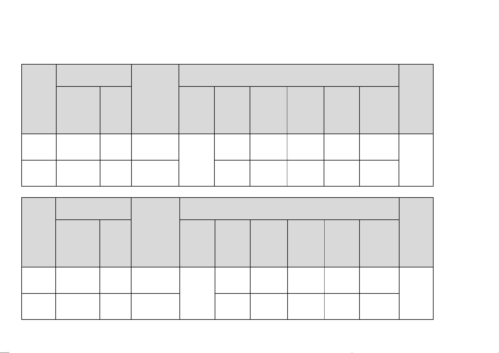
Model
Board
BTLE
Chipset
BTLE Chipset
FCC ID
Name
CMSIS-
DAP
Package
Internal
Flash
Memory
(KB)
Internal
Mask
ROM(KB)
Internal
Work
RAM(KB)
Internal
Silicon
OSC
Internal
Randam
Number
Generator
Model-1
SAPPHIRE-
678FSG
No
TC35678FSG
QFN
40pin
256
384
192
Yes
No
2AKW4-
678FSG
Model-2
SAPPHIRE-
679FSG
No
TC35679FSG
No
384
192
Yes
No
Model
Board
BTLE
Chipset
BTLE Chipset
FCC ID
Name
CMSIS-
DAP
Package
Internal
Flash
Memory
(KB)
Internal
Mask
ROM(KB)
Internal
Work
RAM(KB)
Internal
Silicon
OSC
Internal
Randam
Number
Generator
Model-1
SAPPHIRE-
67CFSG
Yes
TC3567CFSG
QFN
40pin
128
216
128
No
Yes
2AKW4-
678FSG
Model-2
SAPPHIRE-
67DFSG
Yes
TC3567DFSG
No
216
128
No
Yes
2. Overview
The differences between each model are shown following table.
ORIGINAL
This model

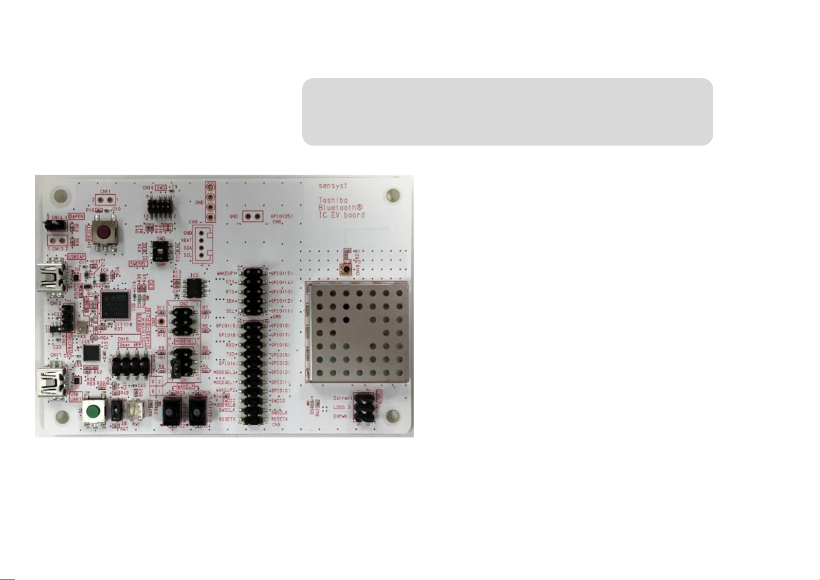
3. Overview Appearance
(1) Power Select Pin
Metal Shield
RF Switch Connector
(Hirose MS-156C)
Antenna
Toshiba
(2) Mode Select Pin
(3) I/O Pin Header
GND Pin
(not mounted)
Reset
Button
(6) Half pitch 10 pin
Connector for SWD
LED
Volume
Toggle Switch
For Wake Up15
Dip Switch
Push Button
(5) Mini-USB Connector
(4) Pin Header for User-App
Volume and LED
CMSIS-DAP circuit
Toggle Switch
For Wake Up 0
Grove Connector for I2C devices
(not mounted)
(7) Mini-USB Connector
(8) Pin Header
(9) Pin Header
The difference in appearance between SAPPHIRE-67CFSG & SAPPHIRE-67DFSG and SAPPHIRE-678FSG & SAPPHIRE-679FSG is that we added parts for CMSIS-DAP.
(for enable CMSIS-DAP)
(Newly Added)
(for selecting VBUS)
Push Button, Dip Switch,
(partly not mounted)
Bluetooth LE IC
(BTLE IC)

4. Block Diagram
4-1. SAPPHIRE-67CFSG (2AKW4-678FSG)

4-2. SAPPHIRE-67DFSG (2AKW4-678FSG)

5. Features
The SAPPHIRE evaluation board includes Toshiba Bluetooth LE IC complies with Bluetooth v4.2, low energy single-mode radio and has the following features.
[Radio]
Complies with Bluetooth v4.2, low energy single-mode radio operates at 2402 MHz to 2480 MHz.
The qualified Bluetooth protocol stacks such as HCI,GATT are stored in the Bluetooth LE IC.
Bluetooth Device Address, uniquely radio identifier is stored in the Bluetooth LE IC.
Maximum communication distance is approximately up to 30 m with the pattern antenna on this board. (Transmit output power :0 dBm, Sensitivity:-93 dBm)
Hirose MS-156C RF switch connector for radio evaluation is included. If needed for radio evaluation, please prepare suitable RF coaxial adapter(*) yourself.
(*)MS-156R-HRMJ-1
[Power]
USB bus powered is supported. Built-in LDO device produce a 3.3 V power supply to the ICs from Vbus 5 V.
Pin headers for external power supply such as coin battery are included.
Pure current of the Bluetooth LE IC can be measured at the pin headers on the board.
[GPIO]
All GPIOs of the bluetooth LE IC can be directly contacted at the pin headers on this board. (But partly headers are not mounted)
SAPPHIRE-67CFSG and SAPPHIRE-67DFSG support GPIO 0 to 15 and GPIO 25.
[Peripheral]
Either HCI mode or User-App mode can be selected by the configuration of Mode Select Pin.
Silicon labs CP2104 device, USB-UART bridge IC enables UART communication with PC and Bluetooth LE IC. USB type A male to mini B male cable is not included.
512KB EEPROM device is on this board. The SAPPHIRE-67DFSG boots up from this EEPROM device for User-App mode.
Toggle switch for Wake up 0 and wake up 15
A push switch, a dip switch, a LED and a volume for user application can be connected to the any GPIOs with wire cables.
Half pitch 10 pin connector for SWD debugging and programming.
Grove Universal 4 pin connector can be mounted on this board for connecting the various I2C shield modules.
Supports on-board debugging function. You do not need an another debugger. You can debug and program by connecting with PC and USB type A male to mini B male cable.

6. Transmission Operation
(1) Check the jumper position on this board so that it can be communicated
real COM port from the reference point of both the host application and
with a PC via virtual COM port..
(1) Get the latest version of the CP210x USB to UART Bridge VCP Driver
on the Silicon Labs website:www.silabs.com/interface-software and
install this to the PC.
(2) Connect the SAPPHIRE Evaluation board to the PC using standard
the serial device.
(4) Send commands using Host application such as Toshiba HCI Testers to
operate the Bluetooth LE IC on this board or download a program to the
NVM for user applications. Refer Toshiba website for more informations.
USB Type A Male to Mini B Male Cable.
(3) The CP210x device will be apper as a COM port in device manager in
Windows. As a virtual COM port,the CP210x functions identically to a
https://toshiba.semicon-storage.com/us/product/wireless-
communication.html

7. Feature Description
User-App Mode
HCI Mode
GPIO 1
H or Open
L
CN1
GPIO 2
Don’t care
L
CN2
GPIO B
Don’t care
H or Open
CN1
GPIO
1
GPIO
2
GPIO
B
Reserve
QFN 40pin / QFN6
0 pin
common
QFN60 pin
only
QFN 40pin / QFN60 pin common
No Mount
(1) Power Select Pin(CN4)
(2) Mode Select (CN1-2)
Depending on the mounting of the jumper socket, you can switch
(3) I/O Pin Header (CN5-8)
To this pin header
Use this pin header when selecting the power supply for the
Bluetooth LE IC.
And measuring the current consumption of the Bluetooth LE IC.
.
NOTE1 (Selecting Power Supply)
When using external power supply, be sure to open 3-4 pin to
avoid collision with LDO output.
NOTE2(Current measurement)
By connecting an ammeter to 1-2 pin, it is possible to measure
consumption current of Bluetooth LE IC alone. .
between HCI mode and User-App mode. Since the mode is
confirmed immediately after releasing reset, you can use it in any
state after booting.
・Reset input of Bluetooth LE IC
・SWD interface
・All GPIOs of each IC are connected
Since no other circuit is connected between IC and pin header, it
can contact directly with IC terminal. CN8 is not mounted. If you
use GPIO24-31, you need to install a pin header to CN8.

(4) Pin Header for User-App (CN16)
Pin No.
Access Point
Descriptipn
1
Push Button
H or L
Pushing is L.
2
GND
GND
3
Dip Switch
H or L
4
GND
GND
5
Volume
Separating I/O volatage
6
GND
GND
7
LED (Red)
Lighting is L.
8
GND
GND
(5) Mini-USB Connector (CN17)
(7) Mini-USB Connector (CN12)
This pin header is for user application evaluation.
The connection destination of each pin is shown in the table below.
Power Select (Please show Power select pin)
By connecting a USB cable to this connector, Bluetooth LE IC
can be controlled with UART from Windows PC.
When using this function, it is necessary to download and install
the VCP driver from the Silicon labs company website in
advance.
(6) Half Pitch 10 pin Connector for SWD Connector (CN10)
It is for ARM debugger connection. You can debug the Bluetooth
LE IC with the SWD interface.
Debugging function is exclusive with CMSIS-DAP(CN12).
It is for CMSIS-DAP. You can debug the Bluetooth LE IC without
using an external debugger.
Debugging function is exclusive with SWD Connector(CN10).
(8) Pin Header (CN14)
Shorting this pin header enables the CMSIS-DAP function..
(9) Pin Header (CN15)
This Pin Header is for selecting VBUS power supply.
1-2 → Power is supplied from CN17.
2-3 → Power is supplied from CN12.

8. BLE Chip Specification
Please refer to
TC3567CFSG-001_SummaryCatalog_en_20170626.pdf
TC3567DFSG-001_SummaryCatalog_en_20170626.pdf
https://toshiba.semicon-storage.com/us/product/wireless-communication/bluetooth/detail.TC3567CFSG-001.html
https://toshiba.semicon-storage.com/us/product/wireless-communication/bluetooth/detail.TC3567DFSG-001.html

9. Appendix
3 H L H ON
ON
DAP
The following picture shows the setting when using CMSIS-DAP function.
It is necessary to receive the PC driver for CMSIS-DAP from Toshiba Electronic Devices & Storage Corp.
For details, refer to the following URL.
https://toshiba.semicon-storage.com/us/product/wireless-communication/bluetooth.html
For details of CMSIS-DAP, please refer to the following URL.
https://developer.arm.com/embedded/cmsis
For development tools, please refer to the following URL.
http://www.keil.com/support/man/docs/dapdebug/dapdebug_introduction.htm
https://www.iar.com/jp/iar-embedded-workbench/tools-for-arm/cmsis/
 Loading...