

Sensys Networks VDS240 Installation Manual

APCC
Sensys Networks VDS240 Wireless Vehicle
Detection System
Access Point Controller Card (APCC) Installation Guide
P/N 152-240-030-005, Rev F
June 2015

Document Properties
This document is reference material for the Sensys Networks VDS240 wireless vehicle
detection system from Sensys Networks, Inc.
P/N 152-240-030-005 Rev F
Sensys Networks, Inc. makes no representation or warranties with respect to the
contents hereof and specifically disclaims any implied warranties of merchantability or
fitness for any particular purpose. Furthermore, Sensys Networks reserves the right to
revise this publication and to make changes from time to time in the content hereof
without obligation of Sensys Networks to notify any person or organization of such
revisions or changes.
© 2007 - 2015 – All rights reserved.
Sensys Networks and the Sensys Networks logo are trademarks of Sensys Networks,
Inc. All other products, names and services are trademarks or registered trademarks of
their respective owners.
Regulatory Statements
FCC Compliance Statement
This device complies with part 15 of the FCC rules. Operation is subject to the following
two conditions:
Any changes or modifications to this product not authorized by Sensys Networks could
void the EMC compliance and negate the authority to operate the product.
RF Exposure Statement
This device has been tested and meets the FCC RF exposure guidelines. It should be
installed and operated with a minimum distance of 20 cm between the radiator of RF
energy and the body of users, operators, or others.
Improper use or tampering with the device is prohibited and may not ensure
compliance with FCC exposure guidelines.
Warnings
No Safety Switching
Sensys Networks does not allow its equipment to be used for safety applications such
as controlling a mechanical gate or switching a train to avoid a collision.
(1) This device may not cause harmful interference.
(2) This device must accept any interference received, including interference that
may cause undesired operation.

Lithium Thionyl Chloride Batteries
N
OTE
:
Sensys Networks uses Lithium Thionyl Chloride batteries in the following products:
Sensors (VSN240-F, VSN240-T, VSN240-S, VSN240-M, VSN240-F-2,
VSN240-T-2)
Repeaters (RP240-BH-2, RP240-BH-LL-2, FLEX-RP-B-2, FLEX-RP-B-LL-2)
Lithium batteries are widely used in electronic products because they contain more
energy per unit -weight than conventional batteries. However, the same properties that
deliver high energy density also contribute to potential hazards if the batteries are
damaged. Improper use or handling of the batteries may result in leakage or release of
battery contents, explosion, or fire.
Following are the recommendations of the battery manufacturer for proper use and
handling of batteries in the Sensys Networks devices mentioned above:
DO NOT charge or attempt to recharge the batteries (they are NOT
rechargeable)
DO NOT crush or puncture batteries
DO NOT short-circuit the batteries
DO NOT force over-discharge of the batteries
DO NOT incinerate or expose batteries to excessive heating
DO NOT expose battery contents to water
DO dispose of batteries and devices containing batteries in accordance with
local regulations
Sensys Networks wireless sensors contain no serviceable parts and should never be
disassembled. Installation and removal of sensors from pavement should only be done by
trained personnel and care should be taken to insure that the sensor casing is not punctured
or crushed.
Additional safety information is available from the battery's manufacturer:
Sensor and repeater battery cell: http://www.ewtbattery.com/en/
DownView.asp?ID=9
Document Control
Sensys Networks continually reviews and revises its technical publications Please
address questions, suggestions, or corrections to support@sensysnetworks.com.

Sensys Networks Technical Publications
For additional information regarding Sensys Networks products and applications,
design guides, configuration guides, and best practices, refer to the Sensys Networks
technical documents library available at http://sensysnetworks.com/
resources?tech_docs.
Contact Information
Sensys Networks, Inc.
1608 Fourth Street, Suite 200
Berkeley, CA 94710 USA
+1 (510) 548-4620
www.sensysnetworks.com

Contents
Chapter 1: Introduction ............................................................................................... 1
What's Inside ..................................................................................................................................1
Chapter 2: Overview ................................................................................................... 3
Access Point Controller Card (APCC) ........................................................................................3
Contact Closure Expansion Card .........................................................................................3
Types of APCC Configurations ....................................................................................................4
APCC System ..........................................................................................................................4
APCC Serial Port Protocol (SPP) Digital Radio ..............................................................5
Isolator ...............................................................................................................................5
APCC Package Contents ............................................................................................................5
SPP Package Contents .................................................................................................................6
Universal Mounting Kit Contents ...........................................................................................7
Additional Parts and Equipment Required ................................................................................8
Chapter 3: APCC Installation Considerations ........................................................... 9
Identifying the SPP and Sensors ...................................................................................................9
SPP ............................................................................................................................................9
Wireless Sensors .....................................................................................................................10
Determining the Device Configuration ....................................................................................10
Configuration Worksheet .....................................................................................................10
Determining Slots and Contact Closures .................................................................................11
Mapping Wireless Sensors to Contact Closures .......................................................................12
Chapter 4: SPP Installation Considerations .............................................................. 13
Powering the SPP ........................................................................................................................13
Acquiring Power From a Traffic Controller .........................................................................13
Acquiring Power From Traffic Controller Using an Isolator ...............................................14
Voltages .................................................................................................................................15
Cabling ..................................................................................................................................15
Collecting Data From the APCC ...............................................................................................15
Determining the Location of the SPP ........................................................................................15
Optimal Location Criteria ....................................................................................................15
Chapter 5: APCC Installation Procedures ................................................................ 17
Overview ......................................................................................................................................17
Determining the Card ID and Setting it via Circuit-board Dip Switches SW1 and SW2 ......17
Factory Default Card ID .......................................................................................................18
Querying the Backplane for an Assigned Address ...........................................................18
Setting the Slot-Number With Circuit-board Dip Switch SW2 ...........................................19
Sensys Networks, Inc. Access Point Controller Card (APCC) v
Installation Guide

Exception ........................................................................................................................19
Setting the Shelf-Number With Circuit-board Dip Switch SW1 ........................................19
Determining the Controller Type and Setting it via Circuit-board Dip Switch SW1 .............19
Connecting the Cables to Each Device .................................................................................20
Cabling Summary .......................................................................................................................21
Chapter 6: SPP Installation Procedures .................................................................... 23
Tools Required for SPP Installation .............................................................................................23
Step-by-Step Procedures ...........................................................................................................24
Installing the Mounting Plate on Poles ...............................................................................24
Installing the Mounting Plate on Walls ...............................................................................25
Installing the Mounting Plate on Beams .............................................................................25
Determining the Type of SPP Radio Bulkhead Connector ..............................................26
SPP Radio Bulkhead Connector ...................................................................................26
Connecting the Cable to an SPP Radio with the Hex-head Connector .......................26
Components ...................................................................................................................26
Step-by-Step Procedures .....................................................................................................27
Proper Fit (little to no gap between edges of cut) ....................................................30
Improper Fit (gap between edges of cut) ..................................................................30
Proper Fit (bushing fully seated into guides) ...............................................................31
Improper Fit (bushing poorly seated into guides) ......................................................32
Proper Fit (recessed bushing, smooth face) ...............................................................33
Improper Fit (bushing not recessed, pinched edge, mushroomed face) ..............33
Removing the Cable Connection ......................................................................................33
Chapter 7: Configuration .......................................................................................... 35
Overview ......................................................................................................................................35
Configuration Methods ........................................................................................................36
Configuring Channels With the Front-Panel Interface ............................................................36
General Procedure ..............................................................................................................36
Saving the Configuration ..............................................................................................37
Enabling / Disabling a Channel ..........................................................................................37
Specifying the Channel Mode ............................................................................................38
Setting a Presence Mode Modifier (Optional) ..................................................................38
Using Delay and Extension ............................................................................................38
Specifying the Type of Communication Used by the Channel Status Monitor ............39
Starting TrafficDOT and Connecting to an APCC ...................................................................40
Configuring Channels with TrafficDOT ......................................................................................42
Entering controller card information ..................................................................................42
Configuring Channel State .................................................................................................43
Configuring Channel Mode ................................................................................................43
Configuring Presence Mode Modifier ................................................................................44
Configuring Channel Holdover Duration ...........................................................................44
Defining Sensor-to-Channel Mappings ....................................................................................44
Exiting TrafficDOT .........................................................................................................................45
Appendix A: X Mode LED Displays for Slot Numbers .............................................. 47
Examples ......................................................................................................................................48
vi Access Point Controller Card (APCC)
Installation Guide Sensys Networks, Inc.

Appendix B: Circuit-board Dip Switch SW1 Settings ............................................... 49
Settings for Shelf Number ...........................................................................................................49
Settings for TS1 and TS2 Controllers ...........................................................................................50
Appendix C: Circuit-board Dip Switch SW2 Settings .............................................. 51
Settings for Slot Number .............................................................................................................51
Appendix D: Pre-Installation Worksheets ................................................................ 53
Appendix E: Contact Closure Card External Interfaces ......................................... 55
Backplane Edge Connections ..................................................................................................56
IN RJ45 Connector Pin Assignments ..........................................................................................58
OUT RJ45 Connector Pin Assignments ......................................................................................58
Sensys Networks, Inc. Access Point Controller Card (APCC) vii
Installation Guide

viii Access Point Controller Card (APCC)
Installation Guide Sensys Networks, Inc.

Introduction
This guide provides information and procedures for installing Sensys Networks
Access Point Controller Card (APCC) and the APCC Serial Port Protocol (SPP)
digital radio in conjunction with the Sensys Networks VDS240 wireless vehicle
detection system. This document is intended to be used by Sensys Networks
customers, consultants, partners, dealers, and those who are interested in the
application of wireless communication technology to the challenges of traffic
detection, management, and control.
Chapter 1
What's Inside
This guide includes the following information:
Chapter 1: Introduction, defines the purpose and scope of the guide.
Chapter 2: Overview, provides an overview of the APCC and its additional
components. It also describes the contents of a product shipment.
Chapter 3: APCC Installation Considerations, provides the installation
considerations for the APCC.
Chapter 4: SPP Installation Considerations, provides the installation considerations
for the SPP.
Chapter 5: APCC Installation Procedures, provides instructions for installing and
cabling the APCC.
Chapter 6: SPP Installation Procedures, provides instructions for installing and
mounting the SPP.
Chapter 7: Configuration, provides instructions for configuring an APCC and
expansion cards.
Appendix A: X Mode LED Displays for Slot Numbers, depicts the channel LED
displays when an APCC operates in X mode.
Access Point Controller Card (APCC) 1
Sensys Networks, Inc. Installation Guide

Chapter 1
Appendix B: Circuit-board Dip Switch SW1 Settings, depicts SW1 settings that
identify the shelf number portion of the unique card address.
Appendix C: Circuit-board Dip Switch SW2 Settings, depicts combinations of switch
settings on the circuit-board dip switch SW2.
Appendix D: Pre-Installation Worksheets, provides worksheets for capturing
pre-installation information.
Appendix E: Contact Closure Card External Interfaces, provides the connector pin
assignments for the external interfaces of contact closure master and
expansion cards.
2 Access Point Controller Card (APCC)
Installation Guide Sensys Networks, Inc.

Overview
This chapter provides an overview of the APCC and its additional components.
The chapter also describes the contents of a product shipment.
Access Point Controller Card (APCC)
Chapter 2
The Sensys Networks VDS240 Wireless Vehicle Detection System detects the
presence and movement of vehicles with magneto-resistive sensors mounted in
the pavement. Wireless sensors continuously transmit detection data to the APCC
that collects and forwards data to remote traffic management systems or local
traffic signal controllers such as the CalTrans Type 170, Type 2070 ATC and
NEMA TS-1, and TS-2 controllers.
The Sensys Networks Access Point Controller Card (APCC), is a second generation
controller card that maintains low power consumption, supports multiple radios,
and allows for additional communication and processing power. The APCC, which
is compatible with all of Sensys Networks VDS240 Wireless Vehicle Detection
System products, receives and processes data from the sensors. The APCC then
relays the sensor detection data to a roadside traffic controller or remote server
traffic management system.
Contact Closure Expansion Card
Additional capacity (to handle more sensors or controller channels) is provided by
a contact closure expansion card (EX card). EX cards use the same form factor as
APCC cards and are daisy-chained to a CC interface on the APCC on the front-
panel RJ45 jacks or backplane connectors. Up to 63 EX cards can be used per
APCC card.
Access Point Controller Card (APCC) 3
Sensys Networks, Inc. Installation Guide

Chapter 2
Types of APCC Configurations
The APCC single-slot configuration consists of dual APCC radio ports, Sensys
Networks Expansion (EX) port, and contact closure interface via backplane to a
traffic controller. It also has dual USB 2.0 full speed host ports and 10/100Base-T
network access. The APCC dual-slot configuration adds an SD memory card, real-
time battery-backed clock, dual serial (DB9) interface, or an optional built in
cellular modem.
APCC System
The minimum APCC system consists of an APCC and one SPP radio. The system
can also consist of multiple SPP radios and an isolator that offers electrical
isolation up to 1500V, surge protection up to 1500V, and AC power cross
protection.
Figure 2.1. APCC configurations
Figure 2.2. APPC system configuration
4 Access Point Controller Card (APCC)
Installation Guide Sensys Networks, Inc.
APCC Serial Port Protocol (SPP) Digital Radio
The APCC, along with the SPP, maintains two-way wireless links to an
installation’s sensors and repeaters, establishes overall time synchronization, and
transmits configuration commands and message acknowledgements.
Figure 2.3. SPP digital radio
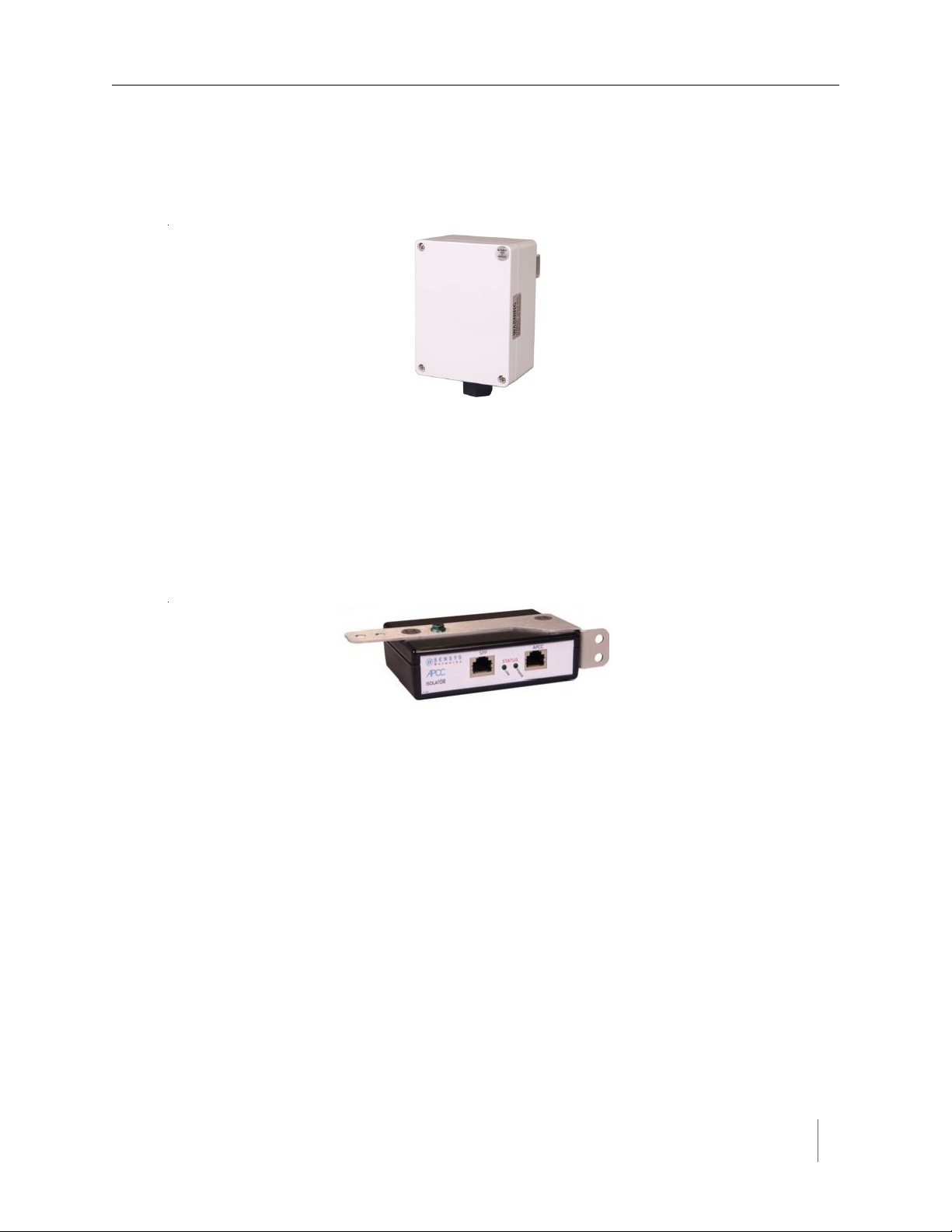
Isolator
The isolator is an optional component that provides the following services:
connects an SPP to the APCC
isolates and routes power from the controller backplane to the SPP
Overview
extends the communication for the APCC to and from the SPP at RS422
distance.
Figure 2.4. Isolator
APCC Package Contents
Each APCC is shipped with the items listed below. Verify that you have received all
of them. In the event that some items are missing, contact Sensys Networks or the
party that supplied the equipment to you.
The items in a Sensys Networks APCC shipment include:
An APCC
Access Point Controller Card Installation Guide (this document)
Information sheet
The Sensys Networks APCC is shipped with a factory default configuration suitable
for bench-testing the device and typically require further configuration to meet the
needs of specific applications. Hardware serial numbers are found on the
information sheet.
The APCC and EX cards are available in the models as shown below. Verify that
you have the correct model for your application.
Access Point Controller Card (APCC) 5
Sensys Networks, Inc. Installation Guide

Chapter 2
N
OTE
:
Product Description
APCC-M APCC Module
APCC-M-E APCC Module with Enhanced Ethernet
APCC-MP-E APCC Module with Peripheral Support and Enhanced Ethernet
APCC-MP-EG APCC Module with Peripheral Support and Enhanced Ethernet, GSM
APCC -MP-EV APCC with Peripheral Support and Enhanced Ethernet, Verizon
EX240 Expansion Card for Type 170, Type 2070, or NEMA TS1 or
TS2 traffic controllers
SPP Package Contents
Each SPP is shipped with the items listed below. Verify that you have received all
of them. In the event that some items are missing, contact Sensys Networks or the
party that supplied the equipment to you.
Table 1. APCC models
The items in an SPP shipment include:
An SPP
“Tool less” push/pull Ethernet bulkhead connector
Information sheet (one per device)
Item that is shipped separately:
Universal mounting kit (kit can be purchased from Sensys Networks)
SPP digital radios are shipped with a factory default configuration suitable for
bench-testing the device and applicable to many field environments. The
information sheet details the physical attributes of the SPP as well as key
configuration elements.
SPP information sheets contain the following elements:
Serial number – a globally unique identifier for the SPP
Default RF channel – a critical configuration property
Default IP address
Firmware release version
RF channel is essential for communicating and further configuring the wireless sensor
network. Save all information sheets for the party who will configure and use the network
after it is installed. Refer to the Configuration chapter of the Sensys Networks VDS240
Wireless Vehicle Detection System Reference Guide for more information about network
operations and configuration.
6 Access Point Controller Card (APCC)
Installation Guide Sensys Networks, Inc.
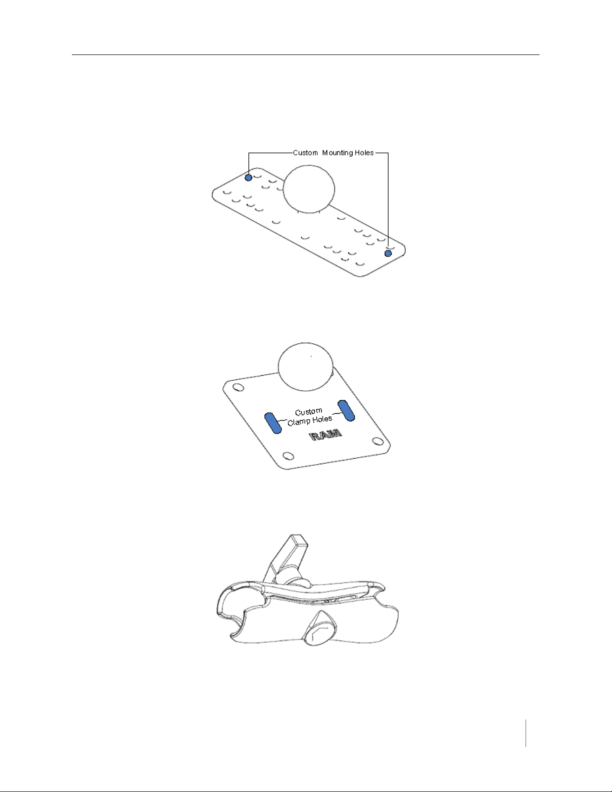
Universal Mounting Kit Contents
The following parts are included in the SPP mounting kit:
SPP ball plate (rectangular, attached to the SPP at the factory, refer to Figure
2.5)
Figure 2.5. Factory installed ball plate (rectangular)
Surface mounting ball plate (square, refer to Figure 2.6)
Overview
Figure 2.6. Surface (wall/beam/pole) mounting ball plate (square)
Double socket arm (refer to Figure 2.7)
Figure 2.7. Double socket arm
Access Point Controller Card (APCC) 7
Sensys Networks, Inc. Installation Guide

Chapter 2
N
OTE
:
5-foot clamp band
Clamp fastener
Additional Parts and Equipment Required
Additional parts and equipment required for installation and configuration of a
APCC include the following:
Standard Ethernet compatible, outdoor rated, 4-pair CAT5 (or better) cable
(refer to Notes below)
RJ45 jack kit and crimp tool
Cable ties
PC or laptop with Microsoft
(including 64-bit editions) and TrafficDOT, the system management software
tool from Sensys Networks.
The APCC is available with a range of options. Verify that the APCC you are using with the
contact closure card(s) is appropriate for that use.
®
Windows® XP Professional or Windows 7
Notes
1. Cabling – a minimum of one straight-through Ethernet cables are required.
2. Laptop PC and TrafficDOT software – if contact closure cards will be configured via TrafficDOT's GUI, a suitable host is required.
3. Contact closure card functions can be configured from the switches on the front panel eliminating the need for a laptop PC and TrafficDOT.
8 Access Point Controller Card (APCC)
Installation Guide Sensys Networks, Inc.

Chapter 3
APCC Installation Considerations
This chapter provides the installation considerations for the APCC. Prior to
installing an APCC ensure that the following aspects have been considered in the
site design.
1. Identify the devices that will be used with the APCC (refer to
and Sensors
2. Determine the configuration of the APCC (refer to
Configuration
3. Determine the number of available slots in the traffic controller's detector
shelf and which contact closures are required (refer to
Contact Closures
4. Develop the sensor-to-contact closure card mappings (refer to
Sensors to Contact Closures
).
).
).
).
Identifying the SPP and Sensors
SPP
Each APCC must connect to an SPP. This connection supplies power to the SPP
and passes command and configuration data to/from the APCC. There is a one-toone relationship between the APCC and master cards in a network.
Determine the location of the SPP relative to the cabinet that will hold the APCC
card. The Cat5 cable that connects to the SPP to the APCC, via an isolator, must
meet standard length limitations (2,000 ft with isolator) for RS422
communication.
Identifying the SPP
Determining the Device
Determining Slots and
Mapping Wireless
Access Point Controller Card (APCC) 9
Sensys Networks, Inc. Installation Guide

Chapter 3
NOTE:
NOTE:
Wireless Sensors
Each channel of an APCC interfaces a designated set of sensors to a designated
contact closure. Ensure information describing which sensor (or sensors) will
actuate a given APCC is available.
Wireless sensors have a unique identifier known as the Sensor ID. Use this identifier to
refer to sensors in design notes and plans.
Determining the Device Configuration
Configuration of an APCC is based on the following design decisions:
The number of APCC channels enabled
The operating mode (pulse or presence) of each channel
The use of and settings for any optional elements that modify the behavior of
channels operating in presence mode
The channel status communication method (LED-only) used by each channel
Configuration Worksheet
Each APCC supports up to four channels that are separately configured. Design
decisions can be captured in a Channel Configuration Worksheet such as the one
shown below.
Default values are shown in bold.
Configuration
Element
1. Card identifier (Defined by the traffic controller or
installer)
2. Channel 1, 2, 3, 4 1
3. Channel State Enabled | Disabled Enabled
4. Channel Mode Pulse | Presence Presence
4a. Presence Mode
Modifier
4b. Modifier Type None | Delay | Expansion Delay
(applicable only to channels in presence
mode)
Options
Example
Data
4c. Modifier Duration 0 – 31 seconds in 1 sec increments
(Delay, Delay16+)
0 – 7.5 seconds in 0.5 second increments
(Expansion)
10 Access Point Controller Card (APCC)
Installation Guide Sensys Networks, Inc.
5

APCC Installation Considerations
IMPORTANT!
Configuration
Element
5. Channel Holdover
Setting
6. Channel Status
Communications
Other Information
(Optional)
APCC identifier (from APCC) 192.2.68.100
Distance from APCC
(without Isolator)
List of wireless sensor for
the channel
Table 2. Channel configuration worksheet with example data (default values shown in bold)
0 -.75 seconds in .05 second increments 0
LED-only | LED and Tone LED
328 feet (100 meters) – 10BaseT 6 feet
(use SensorIDs of each sensor) 0707
Options
Example
Data
AC15
020D
Notes
1. Contact closure cards are addressed by the Card ID, a value dictated by the
controller or supplied by the installer.
2. Complete one worksheet for each channel.
3. Channel Holdover Setting should not be used; set it to zero.
4. The items listed in the section Other Information are not part of APCC
configuration. They are relevant to other aspects of installing and operating
the APCC.
Determining Slots and Contact Closures
Configuration of contact closure cards depends on (i) the availability of open slots
on the controller backplane and (ii) the use of any predefined functions or phases
for each slot – such as in the case of a standard CalTrans 322 shelf, where one
contact closure card and three contact closure EX cards are required (one card per
phase). Typically, a site survey of the traffic controller is required.
Shelf and slot information from the controller are used to create an identifier,
known as the Card ID, that uniquely defines an APCC in the network.
If using an APCC with an I/O board, it is essential that there is an empty slot directly to the left of
the APCC.
Access Point Controller Card (APCC) 11
Sensys Networks, Inc. Installation Guide

Chapter 3
Mapping Wireless Sensors to Contact Closures
The final installation consideration for contact closure cards are the assignment of
sensors to specific channels.
The four channels represent independent contact closures which, in turn, are
actuated by the vehicle detection events transmitted by a defined group of wireless
sensors. Each sensor may be associated with zero or one Card ID/Channel
combinations.
Up to 15 wireless sensors can be associated with the same card/channel, in which
case the sensors are logically “OR-ed” together – meaning that if any sensor on the
channel detects a vehicle, the corresponding contact closes.
The sensor-to-contact closure channel mappings are stored in a sensor database
that resides in memory. The sensor-to-contact closure channel mappings are
maintained within TrafficDOT.
Defining the channel mappings is aided by the use of a Channel Mapping
Worksheet such as the one shown below.
Card ID
3-02 1 06C2 0 East bound, lane 1
3-02 1 06C3 0 East bound, lane 2
3-05 2 14C7 0 Advance C.3
3-06 3 0404 0 Stop bar A1
3-15 1 05D7 0 West bound, lane 1
Table 3. Sensor-to-channel mapping worksheet with sample data
Channel
(1 - 4)
Sensor ID
Channel
Extension
(opt.)
Location / Lane /
Description (opt.)
Notes
1. The worksheet assumes one sensor per row. Use as many rows as necessary to
assign all necessary sensors to channels.
2. Do not duplicate Sensor ID values. (A wireless sensor may only be assigned
once.)
3. The sample data above depicts representative Card ID values. Since these
values are rarely known prior to field installation, substitute a place-holder
value so that the installer will understand how the wireless sensors are
allocated to the channels.
4. Values for Channel Extension and Location are optional.
12 Access Point Controller Card (APCC)
Installation Guide Sensys Networks, Inc.
 Loading...