

查询SCX100DN供应商
SCX - Series
Precision Compensated Pressure Sensors
FEATURES
· 0 - 1 psi to 0 - 150 psi
· Precision Temperature
Compensation
· Calibrated Zero and Span
· Small Size
· Low Noise
· High Accuracy
· High Impedance for
Low Power Applications
APPLICATIONS
· Medical Equipment
· Barometry
· Computer Peripherals
· Pneumatic Control
·HVAC
GENERAL DESCRIPTION
The SCX series sensors will provide a
very cost effective solution for pressure
applications that require high accuracy over
a wide temperature range. These internally
calibrated and temperature compensated
sensors were specifically designed to
provide an accurate and stable output over
a 0°C to 70°C temperature range. This series
is intended for use with non-corrosive, nonionic working fluids such as air, dry gases,
and the like.
Devices are available to measure absolute, differential, and gage pressures from
1psi (SCX01) up to 150psi (SCX150). The
Absolute (A) devices have an internal
vacuum reference and an output voltage
proportional to absolute pressure. The Differential (D) devices allow application of
pressure to either side of the pressure sensing diaphragm and can be used for gage
or differential pressure measurements.
The SCX devices feature an integrated
circuit sensor element and laser trimmed
thick film ceramic housed in a compact nylon
case. This package provides excellent
corrosion resistance and provides isolation
to external package stresses. The package
has convenient mounting holes and pressure ports for ease of use with standard
plastic tubing for pressure connection.
All SCX devices are calibrated for span
to within ±1% and provide a very low zero
pressure output of ±300 microvolts
maximum. Thus, for many applications,no
trimming networks are required in the signal
conditioning circuitry. If the application
requires extended temperature range ope-
Scale: 1c m
½ inch
ration, beyond 0 to 70°C, two pins which
provide an output voltage proportional to
temperature are available for use with
external circuitry.
The output of the bridge is ratiometric to
the supply voltage and operation from any
D.C. supply voltage up to +30 V is
acceptable.
Because these devices have very low
noise and excellent temperature
compensation, they are ideal for medical
and other high performance applications.
The 100 microsecond response time also
makes this series an excellent choice for
computer peripherals and pneumatic control
applications.
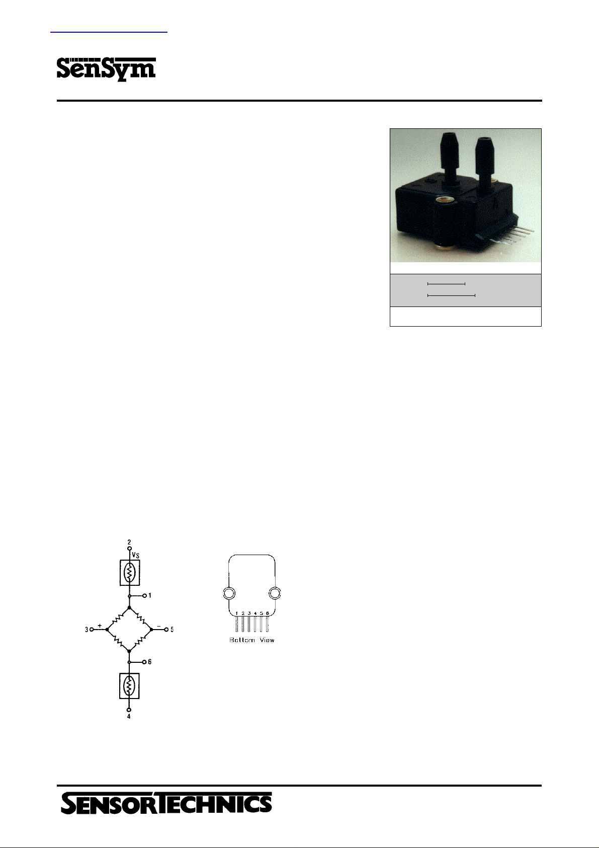
EQUIVALENT CIRCUIT
March 1998/053
ELECTRICAL CONNECTION
Pin 1) Temperature Output (+)
Pin 2) V
Pin 3) Output (+)
Pin 4) Ground
Pin 5) Output (-)
Pin 6) Temperature Output (-)
Note: The polarity indicated is for pressure applied to port B. (For absolute devices
pressure is applied to port A and the output polarity is reversed.)
Aubinger Weg 27, 82178 Puchheim, Germany
Phone 0049 - (0) 89 80 08 30, Fax 0049 - (0) 89 8 00 83 33
http://www.sensortechnics.com
S
SCX - Series
Precision Compensated Pressure Sensors
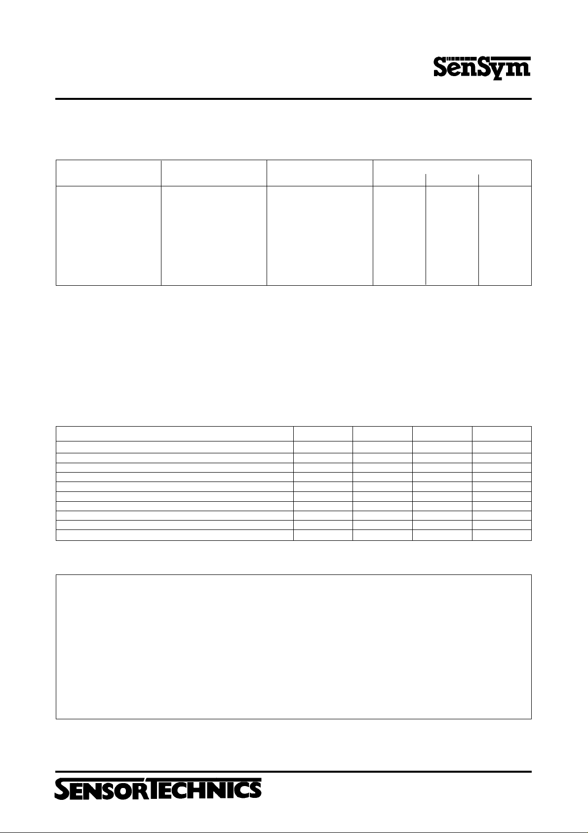
PRESSURE SENSOR CHARACTERISTICS
1
ST ANDARD PRESSURE RANGES
PART NUMBER
SCX01DN
SCX05DN
SCX15AN
SCX15DN
SCX30AN
SCX30DN
SCX100AN
SCX100DN
SCX150AN
SCX150DN
OPERA TING PRESSURE
0 - 1 psid
0 - 5 psid
0 - 15 psia
0 - 15 psid
0 - 30 psia
0 - 30 psid
0 - 100 psia
0 - 100 psid
0 - 150 psia
0 - 150 psid
PROOF PRESSURE*
* Maximum pressure above which causes permanent sensor failure
20 psid
20 psid
30 psia
30 psid
60 psia
60 psid
150 psia
150 psid
150 psia
150 psid
Min.
17.82 mV
59.4 mV
89.1 mV
89.1 mV
89.1 mV
89.1 mV
99.0 mV
99.0 mV
89.1 mV
89.1 mV
FULL-SCALE SP AN
Typ.
18 mV
60 mV
90 mV
90 mV
90 mV
90 mV
100 mV
100 mV
90 mV
90 mV
2
Max.
18.18 mV
60.6 mV
90.9 mV
90.9 mV
90.9 mV
90.9 mV
101.0 mV
101.0 mV
90.9 mV
90.9 mV
Maximum Ratings (For All Devices) Environmental Specifications (For All Devices)
Supply Voltage V
Common-mode Pressure 50 psig Compensated 0 to 70°C
S
+30 V
Lead Temperature Operating -40°C to +85°C
(Soldering, 4 seconds) 250°C Storage -55°C to +125°C
COMMON PERFORMANCE CHARACTERISTICS
Characteristic
Zero Pressure Offset
Combined Linearity and Hysteresis
Temperature Effect on Span (0-70°C)
Temperature Effect on Offset (0-70°C)
Repeatability
Input Impedance
Output Impedance
Common-mode Voltage
Response Time
5
6
7
8
9
Long Term Stability of Offset and Span
3
4
4
10
Temperature Range
DC
Humidity Limits 0 to 100 %RH
1
Min.
-300
---
---
---
---
---
---
5.8
---
---
Typ.
0
±0.1
±0.2
±100
±0.2
4.0
4.0
6.0
100
±0.1
Max.
+300
±0.5
±1.0
±500
±0.5
---
---
6.2
---
---
Unit
µV
%FSO
%FSO
µV
%FSO
kΩ
kΩ
V
DC
µsec
%FSO
SPECIFICA TION NOTES:
1. Reference conditions: Unless otherwise noted: Supply voltage, VS = 12 V, TA = 25°C, Common-mode Line Pressure = 0 psig,
Pressure Applied to Port B. For absolute devices only, pressure is applied to Port A and the output polarity is reversed.
2. Span is the algebraic difference between the output voltage at full-scale pressure and the output at zero pressure. Span is ratiometric to the supply voltage.
3. See Definition to T erms. Hysteresis - the maximum output difference at any point within the operating pressure range
for increasing and decreasing pressure.
4. Maximum error band of the offset voltage and the error band of the span, relative to the 25°C reading.
5. Maximum difference in output at any pressure with the operating pressure range and temperature within 0°C to +50°C after:
a) 1,000 temperature cycles, 0°C to +70°C
b) 1.5 million pressure cycles, 0 psi to full-scale span
6. Input impedance is the impedance between pins 2 and 4.
7. Output impedance is the impedance between pins 3 and 5.
8. This is the common-mode voltage of the output arms (Pins 3 and 5) for V
9. Response time for a 0 psi to full-scale span pressure step change, 10% to 90% rise time.
10. Long term stability over a one year period.
11. Maximum zero pressure offset for absolute devices is 0 ±500 µV.
= 12 VDC.
S
Aubinger Weg 27, 82178 Puchheim, Germany
Phone 0049 - (0) 89 80 08 30, Fax 0049 - (0) 89 8 00 83 33
http://www.sensortechnics.com
March 1998/053
Precision Compensated Pressure Sensors
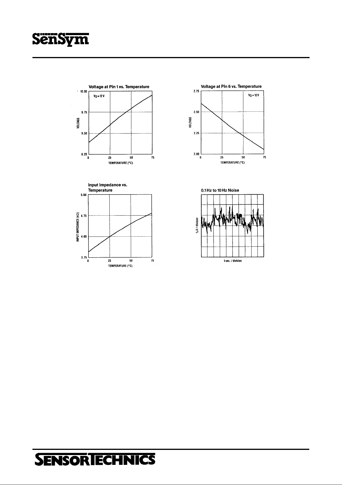
TYPICAL PERFORMANCE CHARACTERISTICS
SCX - Series
GENERAL DISCUSSION
The SCX series devices give a voltage output which is directly
proportional to applied pressure. The devices will give an increasing
positiv going output when increasing pressure is applied to
pressure port P
are reversed, the output will increase with decreases in pressure.
The devices are ratiometric to the supply voltage and changes in
the supply voltage will cause proportional changes in the offset
voltage and full-scale span. Since for absolute devices pressure
is applied to port P
User Calibration
The SCX devices are fully calibrated for offset and span and
should therefore require little if any user adjustment in most
applications. For precise span and offset adjustments, refer to the
applications section herein.
Vacuum Reference (Absolute Device)
Absolute sensors have a hermetically sealed vacuum reference
chamber. The offset voltage on these units is therefore measured
at vacuum, 0 psia. Since all pressure is measured relative to a
vacuum reference,all changes in barometric pressure or changes
in altitude will cause changes in the device output.
Media Compatibility
SCX devices are compatible with most non-corrosive gases.
March 1998/053
of the device. If the input pressure connections
B
, output polarity will be reversed.
A
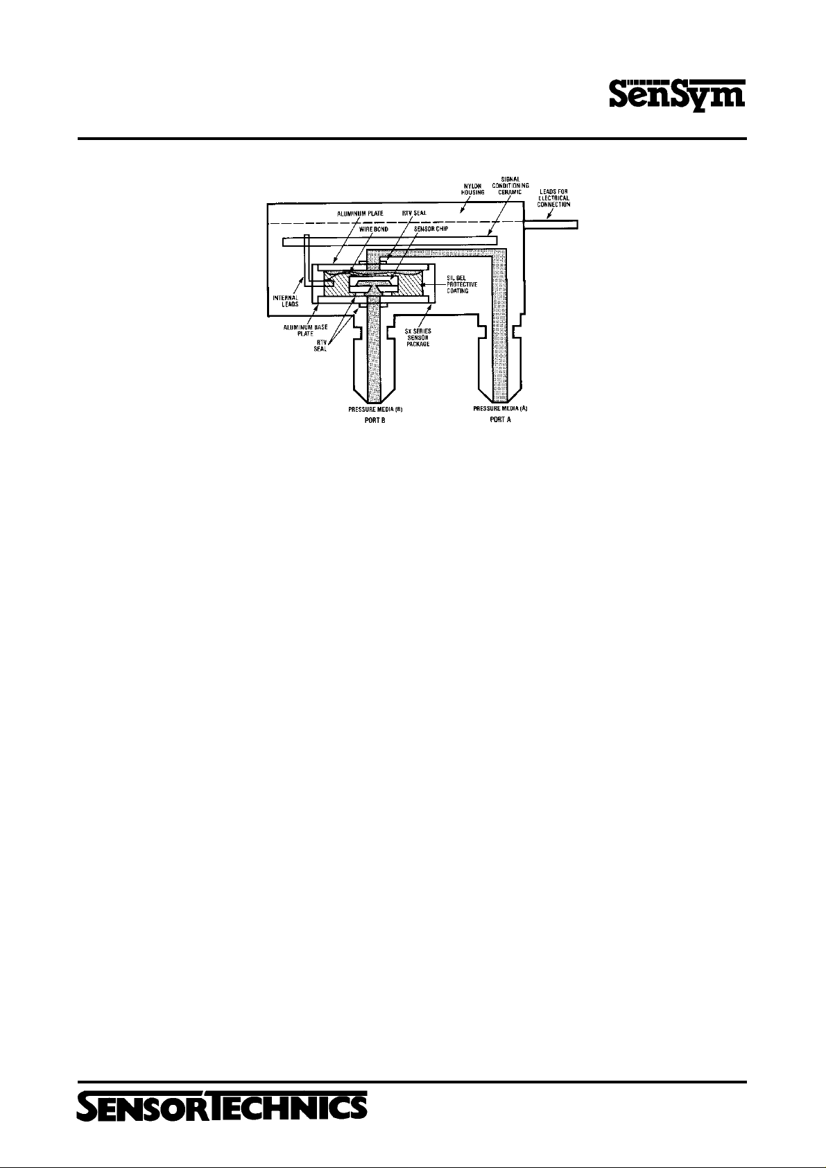
Because the circuit is coated with a protective silicon gel, many
otherwise corrosive environments can be compatible with the
sensors. As shown in the physi-cal construction diagram below,
fluids must generally be compatible with silicon gel, plastic,
aluminium, RTV , silicon, and glass for use with Port B. For questions
concerning media compatibility, contact the factory.
MECHANICAL AND MOUNTING
CONSIDERATIONS
The SCX nylon housing is designed for convenient pressure
connection and easy PC board mounting. To mount the device
horizontally to a PC Board, the leads can be bent downward and
the package attached to the board using either tie wraps or
mounting screws. For pressure attachment, tygon or silicon tubing
is recommended.
All versions of the SCX sensors have two (2) tubes available for
pressure connection. For absolute devices, only port P
Applying pressure through the other port will result in pressure
dead ending into the backside of the silicon sensor and the device
will not give an output signal with pressure.
For gage applications, pressure should be applied the port P
is then the vent port which is left open to the atmosphere. For
P
A
differential pressure applications, to get proper output signal
polarity, port P
should be used as the low pressure port.
should be used as the high pressure port and P
B
Aubinger Weg 27, 82178 Puchheim, Germany
Phone 0049 - (0) 89 80 08 30, Fax 0049 - (0) 89 8 00 83 33
http://www.sensortechnics.com
is active.
A
. Port
B
A
SCX - Series
Precision Compensated Pressure Sensors
Physical Construction (Cutaway Diagram) (Not drawn to scale)
APPLICA TION INFORMA TION
The following circuits show some typical designs using the SCX
series sensors. For specific applications information or assistance,
please contact your nearest Sensym sales office or the Sensym
factory.
Low Pressure Applications
For sensing pressures below 1 psi, the circuit shown in Figure A
uses the SCX01DN to provide a 2 to 5 V output for a 0 to 10 inch of
water column input pressure. This output signal is compatible with
many A/D converters and hence can be used to interface to a
microprocessor system. This low-cost circuit is easily adaptable
to lower full-scale pressures down to 5 inches of water column.
Circuit Description
The LM10 is used to provide a voltage reference for the excitation
voltage (VE), and for the voltage node V
and V
V
E
12 V power supply. R
voltage at the output, V
The pressure signal, V
Sensym Application Note SSAN-17A for details on this amplifier)
is used to adjust the signal gain of the circuit. The output equation
R
2
is given below.
are not affected by noise or voltage variations in the
REF
is used to adjust V
3
.
OUT
, is amplified by amplifiers B1, and B2. (See
IN
= VIN [ 2 (1+ R/R1)]+V
V
OUT
For the best circuit performance, a careful selection of components
in necessary. Use wirebound pots of insure low temperature
coefficients and low longterm drift. A five-element resistor array
(10kΩ) SIP should be used for the resistors in the amplifier stage in
order to obtain closely matched values and temperature
coefficients. All other resistors should be 1% metal film. Amplifiers
, and B2 should have low offset voltage and low noise. Signal
B
1
lines should be as short as possible and the power supply should
be capacitively bypassed on the PC board.
. With this configuration,
REF
to set the initial offset
REF
REF
Adjustment Procedure
1. With zero-pressure applied, adjust the offset adjust R3,
until V
OUT
2. Apply full-scale pressure (10 in. W.C) to port B
full-scale adjust R
3. Repeat procedure if necessary.
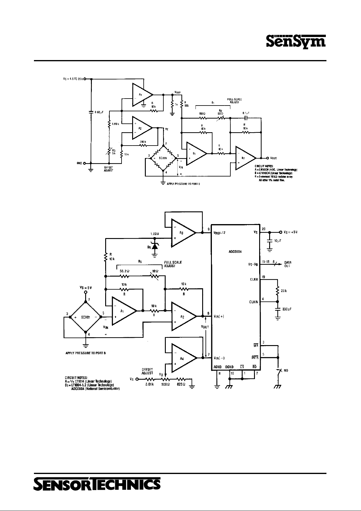
Medical Applications
For blood pressure monitoring applications, the circuit shown in
Figure B provides a 0.5 V to 3.5 V output for a 0 to 300 mm Hg input
pressure. The circuit is easily calibrated and is not affected by
changes in the voltage supply . Because 300 mm Hg is approximately
5.8 psi, an SCX05DN is used.
Circuit Description
The circuit shown here in Figure B is very similar to that shown in
Figure A. The internal 200 mV reference voltage of the LM10 is
amplified to provide power to the sensor and to provide a voltage
reference, V
voltage between 5 and 20 volts without affecting performance of
the circuit. By adjusting R
pressure voltage at V
amplifiers B
with low offset voltages and high common-mode rejection. The
signal gain is adjusted by R
voltage is given by ,
Adjustment Procedure
1. With zero-pressure applied, adjust the offset adjust
, until V
R
3
2. Apply full-scale pressure (300 mm Hg) to port B
R2, until V
3. Repeat procedure if necessary.
= 2.000 V
and adjust the
REF
1
and adjust
1
, so that V
2
. This allows the circuit to operate at a supply
REF
3
. The pressure signal, VIN, is amplified by
and B2. These amplifiers should be precision op amps
1
OUT
2
= VIN [ 2 (1+ R/R1)]+V
V
OUT
= 0.500 V
OUT
= 3.500 V.
OUT
= 5.000 V.
OUT
, V
is used to set the initial zero-
REF
, and the overall equation for the output
March 1998/053
Aubinger Weg 27, 82178 Puchheim, Germany
Phone 0049 - (0) 89 80 08 30, Fax 0049 - (0) 89 8 00 83 33
http://www.sensortechnics.com

Precision Compensated Pressure Sensors
APPLICA TION INFORMA TION (cont.)
Parallel A/D Conversion
The SCX sensor can be easily interfaced to a microprocessor
bus. Using an A/D converter, for a 0 to 1 psig input, the circuit in
Figure C will provide an eight-bit parallel output which is proportional to applied pressure. The circuit allows for easy calibration and
uses a single 5V supply.
Circuit Description
The output signal of the sensor is amplified by A1, and A2. The pot,
in resistor R
shown in the following gain equation:
By adjusting R3, VIN (-) on the A/D converter is used to adjust the
initial offset voltage. A zener diode (LT1004) sets the initial input
voltage and provides the reference voltage for the converter. The
converter will output the maximum digital code when the A/D
converter´s input voltage, V
1
/2 LSB. The A/D converter, as shown, is a free-running
1
configuration where the binary output is updated continously*.
The only requirement is that the WR and INTR must be momentarily
grounded after power-up to ensure proper operation.
Adjustment Procedure
1. With no pressure applied, adjust the offset pot R3 until all bits
are zero except the LSB, which should be switching between
one and zero.
2. Apply full-scale pressure (1 psig) to port B, and adjust the fullscale pot R
be flickering between one and zero.
3. Repeat procedure if necessary.
* For timing specifications and bus interface, see the ADC0804
Datasheet from National Semiconductor.
, can be adjusted to calibrate the gain of the circuit as
1
V
= VIN 2 [1+ R/R1]
OUT
, is twice the zener voltage, minus
OUT
until all bits are ones except the LSB which should
2
SCX - Series
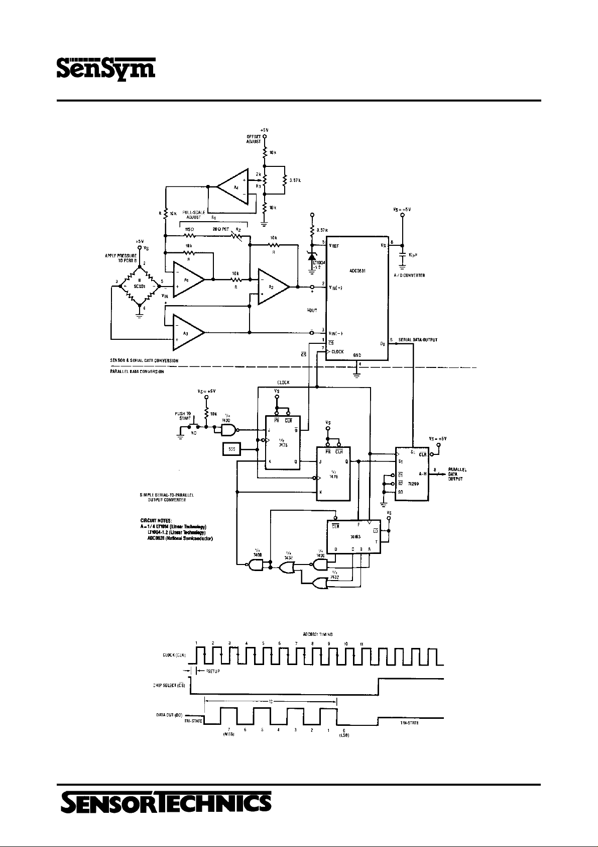
Serial A/D Conversion
The circuit shown in Figure D is similar to that shown in Figure C,
except the output is bit serial. Also shown (under the dashed line)
is a complimentary circuit for converting the serial output to a
parallel output for simplified testing.
Circuit Description
The three op amp configuration allows V
common-mode voltage as V
CMRR of the ADC0831. R
such that
V
= VIN 2 [3/2+ 2R/R1]
OUT
, and takes advantage of the excellent
IN
is used to adjust the gain of the amplifier
2
The A/D converter will output the maximum digital code when V
is equal to the zener voltage minus 1 1/2 LSB. the initial offset of the
circuit can be nulled out by adjusting pot R
requires only a clock and a chip select (CS) line in order to operate.
As shown in Figure E, when CS goes low, the A/D converter will
start a new conversion on the next rising edge of the clock. On the
next falling edge of the clock, D
starting with the MSB, the data out line (D
will have a zero start bit. Then,
O
converted digital output during the next eight consecutive falling
edges of the clock. The serial output can be read by using an
oscilloscope, a microprocessor, or a simple serial-to-parallel
converter as shown in Figure D.
Adjustment Procedure
1. With zero-pressure, adjust R3, until the output of the
A/D converter is alternating between 00 and 01 (HEX).
2. Apply full-scale pressure (1 psig) to port B, and adjust R
l the digital output alternates between the FE to FF transition.
3. Repeat procedure if necessary.
to be at the same
OUT
. The converter circuit
3
) will provide the
O
unti
4
OUT
March 1998/053
Figure A. Low Pressure Circuits Provide a 2 to 5 V Output for a 0-10 in. W.C. Pressure Input
Aubinger Weg 27, 82178 Puchheim, Germany
Phone 0049 - (0) 89 80 08 30, Fax 0049 - (0) 89 8 00 83 33
http://www.sensortechnics.com
SCX - Series
Precision Compensated Pressure Sensors
Figure B. Medical Application Circuit Provide a 0.5 to 3.5 V Output for a 0-300mmHg Pressure Input
Figure C. A Parallel A/D Conversion Circuit for 0-1 psig Applications.
Aubinger Weg 27, 82178 Puchheim, Germany
Phone 0049 - (0) 89 80 08 30, Fax 0049 - (0) 89 8 00 83 33
http://www.sensortechnics.com
March 1998/053
SCX - Series
Precision Compensated Pressure Sensors
March 1998/053
Figure D. Serial A/D Conversion for 0-1 psig Applications and Simple Test Circuit
Figure E. Timing Diagram
Aubinger Weg 27, 82178 Puchheim, Germany
Phone 0049 - (0) 89 80 08 30, Fax 0049 - (0) 89 8 00 83 33
http://www.sensortechnics.com

SCX - Series
Precision Compensated Pressure Sensors
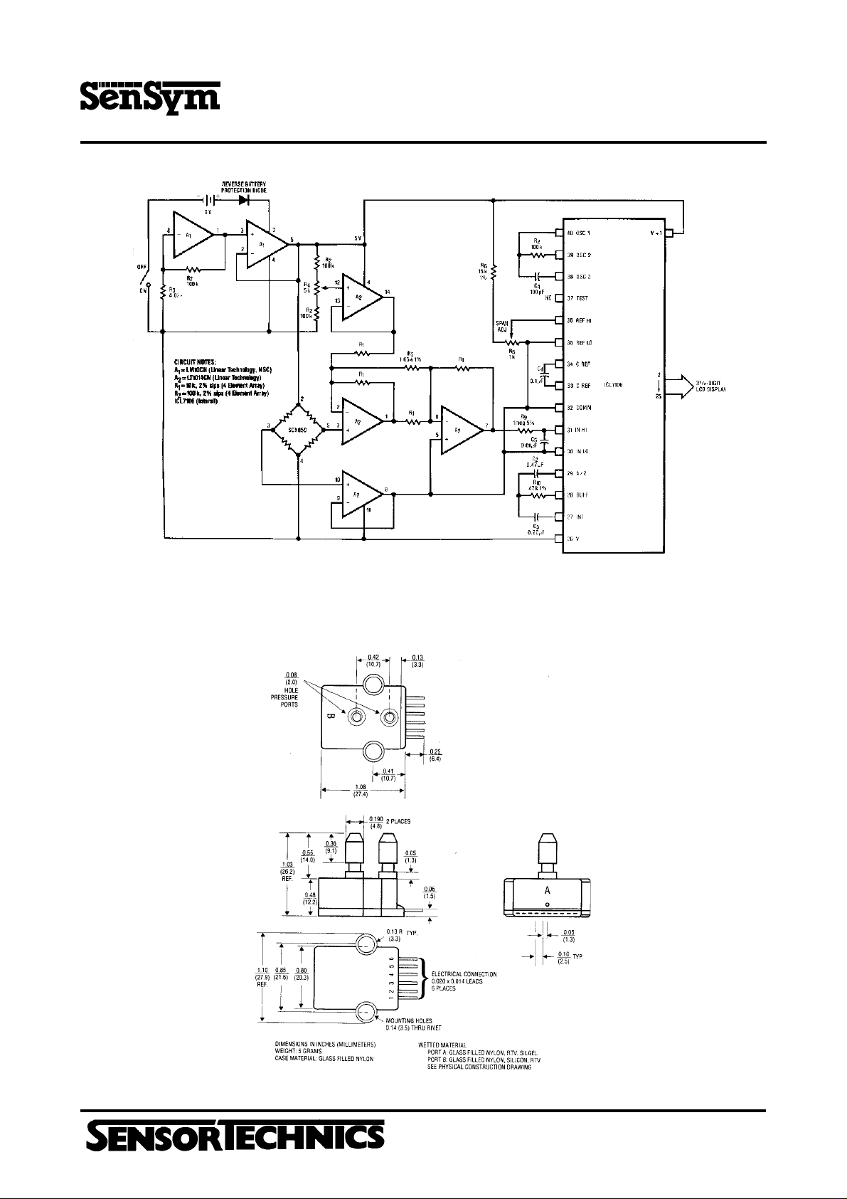
PRESSURE SWITCH
The circuit shown in Figure F is an example of using the SCX01D
to make an accurate 0.5 psi switch. This design can be easily
adapted to other pressure ranges by using higher pressure range
SCX sensors.
Circuit Description
Operating the SCX01D from 5V the sensor will have
sensitivity given on the SCX data sheet. The output at 0.5 psi will
be 3.75 mV . Resistor R
biases the amplifier output voltage to 1.2 V with zero input pressure
and amplifier A
from 0 to 1 psi. Resistors R7 and R8 provide 5 mV of hysteresis to
comparator A
signals. R
taken when laying out the comparator circuit; lead lengths should
to ensure clean transitions for slow movins input
3
sets the switch point for the comparator. Care must be
11
sets the amplifier gain to 269 V/V. Zener D
4
swings from 1.2 V to 3.2 V for an input pressure
2
be as short as possible.
5
/12 the
Adjustment Procedure
Apply 0.5 psi and adjust R11 until the output just switches from a
high state (4.3 V) to a low state (0.0 V).
PORTABLE PRESSURE METER
The circuit shown in Figure G is a 0 to 200 millibar portable pressure
meter. The 3
circuit operates from a single 9 V battery and draws approximately
4.5 mA supply current. This will provide a typical battery life in
excess of 100 hours. The minimum battery voltage is approximately
6.5 V.
1
/2 digit display will read 199.9 millibar full-scale. This
This meter provides resolution to 0.1 millibars. The same circuit
can also be used for other pressure ranges simply by changing
the sensor and gain.
Circuit Description
The LM10CN (A1) is used to generate a regulated 5 V supply to
power the SCX05DN, amplifier A2, and the ICL7106 Amplifier A2 is
a high input impedance diff-in,
diff-out amplifier. The sensor output is amplified to 200 mV full-
1
scale for the A/D input. R
shown. The gain equation is:
R4 is the zero adjust pot and R8 provides the full-scale span
adjustment. The voltage from pin 35 to pin 36 is approximately 100
mV when the display reads 199.9 millibar.
Component Selection
The value of the components R6-R10 and C1-C5 have been optimized
for 200 mV full-scale. (See the Intersil ICL7106 Datasheet). R
should be 15 turn cermet pots, R6-R10 are metal film 1% resistors.
R
8
C3 the integrating capacitor should be polypropylene, the reference
and auto zero capacitors can be polystrene or mylar, the clock
capacitor, C
Adjustment procedure
Apply 195 millibar to the meter and adjust R8 until the display reads
195.0. Apply 0 psig and adjust R4 until the display reads 000.0.
Repeat if required.
A
, is mica.
4
sets the gain to 14V/V for the values
5
= 2 (1 + R1/R5)
V
and
4
Figure F. 0.5 psi Switch
Aubinger Weg 27, 82178 Puchheim, Germany
Phone 0049 - (0) 89 80 08 30, Fax 0049 - (0) 89 8 00 83 33
http://www.sensortechnics.com
March 1998/053
SCX - Series
Precision Compensated Pressure Sensors
PHYSICAL DIMENSIONS
Figure G. 0-200 millibar meter.
March 1998/053
Aubinger Weg 27, 82178 Puchheim, Germany
Phone 0049 - (0) 89 80 08 30, Fax 0049 - (0) 89 8 00 83 33
http://www.sensortechnics.com

SCX - Series
Precision Compensated Pressure Sensors
ORDERING INFORMA TION
To order, use the following part number(s).
Mounting Accessories
Description
0 to 1 psi Differential/Gage
0 to 5 psi Differential/Gage
0 to 15 psi Absolute
0 to 15 psi Differential/Gage
0 to 30 psi Absolute
0 to 30 psi Differential/Gage
0 to 100 psi Absolute
0 to 100 psi Differential/Gage
0 to 150 psi Absolute
0 to 150 psi Differential/Gage
Description
Xmas Tree Clip
Part Number
SCX01DN
SCX05DN
SCX15AN
SCX15DN
SCX30AN
SCX30DN
SCX100AN
SCX100DN
SCX150AN
SCX150DN
Part Number
SCXCLIP
6 Pin Rigth Angle Socket
Pressure Tubing Clamp
SenSym and Sensortechnics reserve the right to make changes to any products herein. SenSym and Sensortechnics do not assume any liability arising out of the application or use of any product
or circuit described herein, neither does it convey any license under its patent rights nor the rights of others.
SCXCNCT
SCXSNP1
March 1998/053
Aubinger Weg 27, 82178 Puchheim, Germany
Phone 0049 - (0) 89 80 08 30, Fax 0049 - (0) 89 8 00 83 33
http://www.sensortechnics.com
 Loading...