

MA-CRANE-BOY_EN
Page 1 on 10
Rev: 11/01/2012
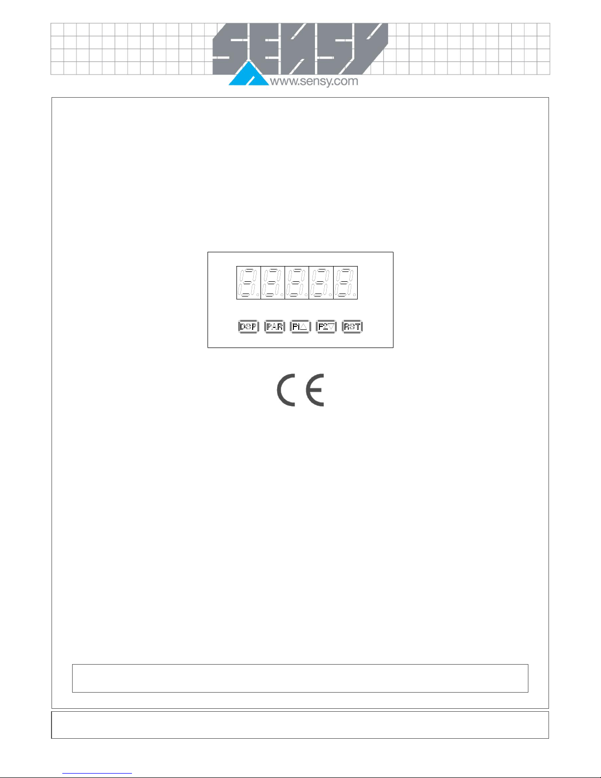
CRANE BOY INDICATOR LIMITER
OEM version name: INDI BOY
1. GENERAL INFORMATION .................................................................................................................................................................2
1.1. Introduction ..................................................................................................................................................................................2
1.2. Principle .......................................................................................................................................................................................2
2. INSTALLATION AND ADJUSTMENTS ...............................................................................................................................................3
2.1. Specific CRANE-BOY connections .............................................................................................................................................3
2.2. System calibration .......................................................................................................................................................................3
2.2.1. 1° Configuring the display and commissioning the limiter ..................................................................................................4
2.2.2. 2° Configuration of the triggering thresholds (set points) ....................................................................................................5
2.3. Correct operation test ..................................................................................................................................................................6
2.3.1. Verification of safety if one of the transducer wires breaks .................................................................................................6
2.3.2. Overload, slack cable and load verification .........................................................................................................................7
2.3.3. Periodic verification .............................................................................................................................................................7
2.3.4. Peak values registration ......................................................................................................................................................7
3. TROUBLESHOOTING.........................................................................................................................................................................8
4. EQUIPMENT REFERENCE AND OPTIONS ......................................................................................................................................8
5. SPECIFICATIONS ...............................................................................................................................................................................9
This indicator can only be used for lifting if these instructions are carefully read, strictly applied and if
the legislation in force is respected.
MA-CRANE-BOY_EN
Page 2 on 10
Rev: 11/01/2012
1. GENERAL INFORMATION
This manual describes the procedure to be followed to install and to adjust the CRANE-BOY, an electronic
load system. The information in this manual is applicable for both CRANE-BOY and INDI-BOY. CRANE-BOY
is an INDI-BOY mounted in an IP65 enclosure.
1.1. Introduction
The CRANE-BOY is an electronic system with a digital display and configurable threshold-based triggers. It
has been modified, tested and qualified by SENSY S.A. to provide for a safe lifting operation.
CRANE-BOY has a monitoring circuit to warn the crane operator of a possible break in the measuring wires.
Therefore, it is a self-monitoring device. In the case of a broken wire, a power cut or a short circuit in either the
supply cable and/or in the transducer measuring cable, the device instantly switches into a positive safety
mode.
It is possible to incorporate as options an analogue output (4-20 mA or 0-10V) and serial communication
(RS232). All available options are listed at the end of the manual.
1.2. Principle
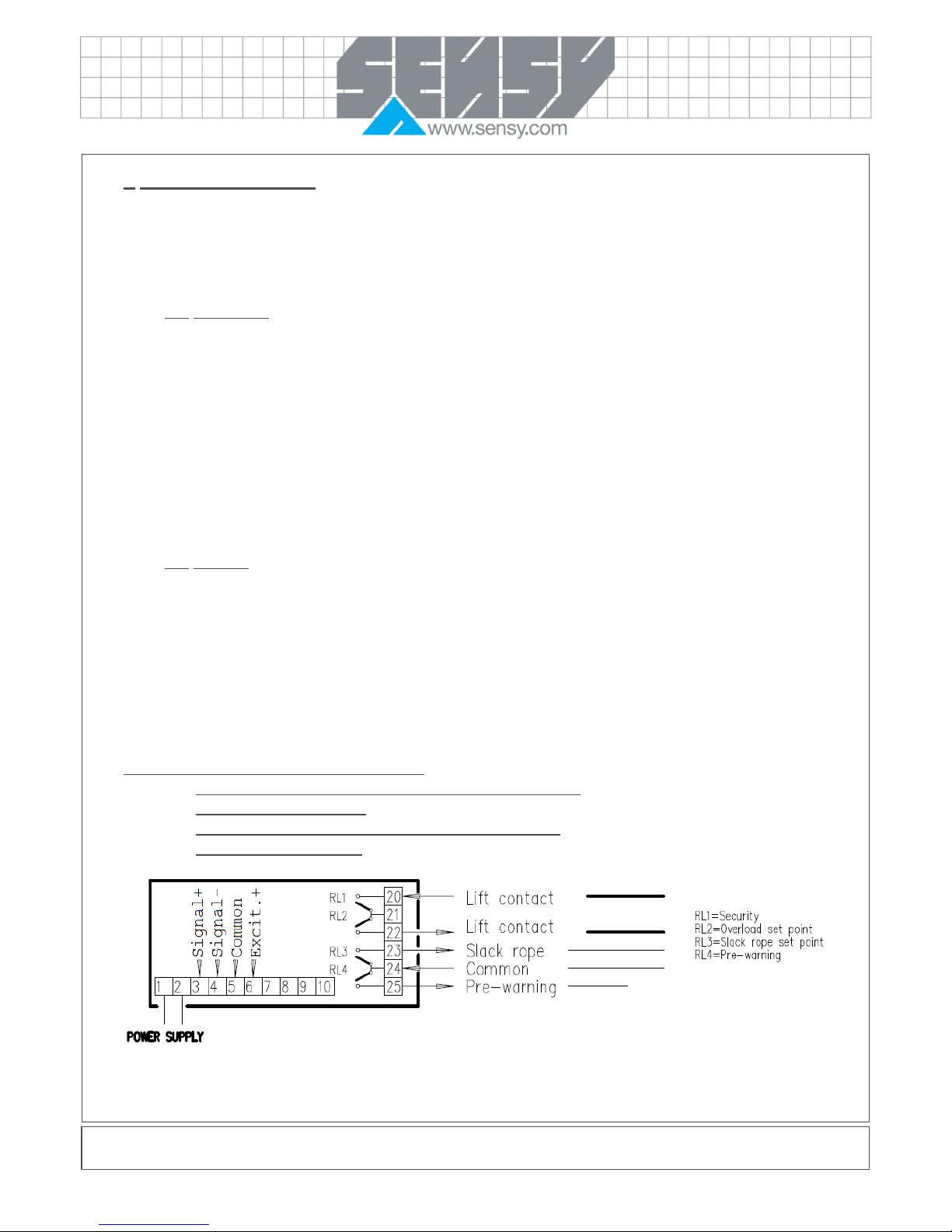
The CRANE-BOY is fitted with a 4-relay board that must be used according to the wiring diagram described
below.
The relays are in the “open” position when the power is shut off (de-energised). When the CRANE-BOY is
turned “on” and the applied load is within the safe operating range, the relays are activated in the "closed"
position (SP1-SP2-SP3-SP4 are displayed in the front panel).
In normal operation, the relays are closed. (SP1-SP2-SP3-(SP4) are displayed in the front panel).
Relay allocation must be strictly respected :
- SP1 (measurement and transducer power supply safety)
- SP2 (overload threshold)
- SP3 (cable slack threshold or intermediate threshold)
- SP4 (optional threshold)
MA-CRANE-BOY_EN
Page 3 on 10
Rev: 11/01/2012
Measuring bridge input
Signal + Green
Signal - White
Excitation - Yellow
Excitation + Brown
2. INSTALLATION AND ADJUSTMENTS
The CRANE-BOY is connected up and adjusted in compliance with the information contained in this manual.
To move around and through the CRANE-BOY's menus, use the buttons or keys on the front panel of the
display.
The PAR key to accept, confirm or enter.
The F1 and F2 keys to go up/down and increase/decrease.
The RST key, in combination with F1 and F2 keys to increase/decrease in steps of 1000 (direct action
on the fourth digit)
The DSP key to quit.
To enter the menus, press the PAR key several times, until CodE appears. Then, using the F1 key, enter the
value of “7”, then press the PAR key. “No” and “Pro” will then appear. You can move from one menu to
another using the F1 and F2 keys.
2.1. Specific CRANE-BOY connections
2.2. System calibration
As the relays that are driven by the different thresholds depend directly on the display, you can only change
some numerical values appearing in menus 1 and 6.

MA-CRANE-BOY_EN
Page 4 on 10
Rev: 11/01/2012
Calibration is carried out in 2 steps:
- 1° display configuration
- 2° threshold configuration
The CRANE BOY programming menu can be accessed via the PAR key. This is organised into function
modules (menus) that group together the parameters associated with each function.
To guarantee that the starting load limitation is correctly followed, the calibration sheet must be duly
completed, dated and signed. Resetting the display is not authorised in any circumstance.
2.2.1. 1° Configuring the display and commissioning the limiter
To configure the display, you must have a known load of at least 70% of the capacity of the transducer’s
Wheatstone bridge or its overload capacity.
Turn the system “on” approximately 15 minutes before starting any adjustment.
If possible, load the system several times to stabilise it mechanically.
Enter menu 1 -INP (using SENSY access code = “7”) and carry out the following operations, using the PAR
key to move on to the next parameter:
DISPLAY
PARAMETER
FACTORY
SETTING
USER SETTING
rANGE
INPUT RANGE
0.02u
. . . . 0,02. . . . .
dECPT
DISPLAY RESOLUTION
0.0
. . . . . . . . .
round
DISPLAY ROUNDING INCREMENT
0.1
. . . . . . . . .
FILtr
FILTER SETTING
1.0
. . . .1.0 . . . .
bANd
FILTER ENABLE BAND
5.0
. . . .5.0 . . . .
Pts
SCALING POINTS
2
. . . . 2 . . . .
StyLE
SCALING STYLE
Select “APPLY” and remove all loads from the crane (in
apply mode, the CRANE-BOY measures the signal of the
load cell).
KEY
. . . APPLY. . .
INP 1
INPUT VALUE 1
1300
Reading at zero (no
load)
dSP 1
DISPLAY VALUE 1
Set to “0”, the value to display when the crane is without
a load (unloaded) by using the F1 and F2 keys and
validate with the PAR key.
0.0
0
INP 2
INPUT VALUE 2
Load the crane with a known load and validate with the
PAR key.
11300
Reading of the signal
under load
dSP 2
DISPLAY VALUE 2
Set to the value to display for the known load and
validate with the PAR key (quit programming mode and
return to display mode)
100.0
Value of the load

MA-CRANE-BOY_EN
Page 5 on 10
Rev: 11/01/2012
Notes :
For each adjustment, INP2 > INP1 and DSP2> DSP1. If this is not the case, check the mounting
direction of the force transducer.
A safe lifting operation is only ensured if the above condition has been satisfied.
After configuring and validating the parameters of your CRANE-BOY, return to display mode (press
the PAR key until “END” appears).
Check that when there is no load, the display is equal to zero and that when the crane is
loaded, the display corresponds to the load that is being lifted.
The details of every parameter are available in the PAXS user guide.
2.2.2. 2° Configuration of the triggering thresholds (set points)
The adjustments in this section are independent of the load lifted at the time of adjustment.
- SP1 is reserved for safety in case either the yellow or brown wire breaks.
- SP2 must be reserved for load limitation: its SP-2 and HYS-2 values will eventually be readjusted to the
characteristics of the transducer’s Wheatstone bridge if this was not carried out at SENSY’s factory.
- SP3 is factory-set to be used for cable slack: its SP-3 and HYS-3 values will eventually be readjusted to
the characteristics of the transducer’s Wheatstone bridge, if this was not carried out at SENSY’s factory.
- SP4 is available to activate a function other than load limitation (but this relay is not protected against a
broken wire). By default, this is not used.
Enter menu “6 –SPt” (SENSY access code = 7) and configure the parameters as shown in the table below.
The SENSY adjustments (factory setting) are such that a lifting system with a force transducer supplying a 1
mV/V signal at nominal capacity (100%) operates in the following way:
- 110% limitation (relay SP2 opens)
- 15% hysteresis (after opening, SP2 closes at 95 %)
- 0% cable slack (SP3 opens)
- 0,1 hysteresis (after opening, SP3 closes at +0,1)
SP2
SP2-Hys
SP3
SP1

MA-CRANE-BOY_EN
Page 6 on 10
Rev: 11/01/2012
The data that must not be changed is written in bold letters
SP1 (security)
SP2 (overload)
SP3 (slack cable)
DISPLAY
PARAMETER
FACTORY
SETTING
USER
SETTING
FACTORY
SETTING
USER
SETTING
FACTORY
SETTING
USER
SETTING
Act - n
SETPOINT ACTION
Ab-LO
Ab-LO
AU-HI
AU-HI
Ab-HI
Ab-HI
SP -n
SETPOINT VALUE
(main)
-3.0%*
Value for a
loose wire (1)
110.0%*
Value for an
overload (2)
0
Value for a
slack cable
(5)
HyS-n
SETPOINT
HYSTERESIS
0.1%*
0.1
15.0%*
15%* (3)
0.1
0.1
tON-n
ON TIME DELAY
0,0
0,0
0,1
0,1 (4)
0,0
0,0
tOF-n
OFF TIME DELAY
0,0
0,0
0,0
0,0
0,0
0,0
out-n
OUTPUT LOGIC
Rev
Rev
Rev
Rev
Nor
Rev
rSt-n
RESET ACTION
AUto
AUto
AUto
AUto
AUto
AUto
Stb-n
STANDBY
OPERATION
No
No
No
No
No
No
Lit-n
SETPOINT
ANNUNCIATORS
Nor
Nor
Nor
Nor
Nor
Nor
* of the nominal capacity
(1) Sufficiently low value to detect a loose wire, by default, -3% of the nominal capacity.
(2) Value at which lifting must be prohibited, according to the legislation in force and the bridge manufacturer's
data.
(3) The hysteresis value may be modified according to the operating conditions. The SP2 activation relay
opens as soon as overloading is reached and only closes when the load is less than the threshold value
minus the hysteresis value.
(4) “tON” (SP2 activation delay) may be modified if the action of lifting a load that is less than the limit load
generates forces (dynamic movements of the load or the “yo-yo” effect) that are greater than those
generated by the static limit load.
(5) Load below which lowering must be prohibited (the SP3 relay opens).
After configuring and validating the parameters of your CRANE-BOY, return to display mode (press the “PAR”
key until “END” appears).
2.3. Correct operation test
The operating test checks that the different relays work and that the wiring is correct, given that the load limiter
must take priority over the commands from the lifting device to prevent any condition that would increase the
overload.
In nominal operation, SP1, SP2 and SP3 are displayed on the front panel.
2.3.1. Verification of safety if one of the transducer wires breaks
For correct verification:
- Disconnect the green wire (+ output) OLOL must be seen on the display and the SP2 overload
relay is off (lifting is impossible)
- Disconnect the white wire (- output) OLOL must be seen on the display and the SP2 overload
relay is off (lifting is impossible)
- Disconnect the brown wire (+ excitation) –xxxxx must be seen on the display and the SP1 and SP3
relays are off (raising and lowering loads are impossible)
- Disconnect the yellow wire (- excitation) –xxxx must be seen on the display and the SP1 and SP3
relays are off (raising and lowering are impossible)

MA-CRANE-BOY_EN
Page 7 on 10
Rev: 11/01/2012
2.3.2. Overload, slack cable and load verification
To verify the overload, first overload and then check that the SP2 relay opens and that lifting is prohibited.
Check that the SP3 relay opens in a slack cable situation and that lowering is prohibited.
Check that the values displayed match the actual values of the loads being handled.
2.3.3. Periodic verification
In compliance with the legislation in force, the lifting force limiter must be regularly checked during periodic
inspections.
This inspection includes a functional test for the triggering limit and the correct condition of the sub-assembly
along with the connections and links. The inspection must be carried out when the equipment is commissioned
then, unless indicated otherwise, at least once a year.
To check the operation of the SP2 overload triggering relay and the display, a test button (*) is fitted on the
load limiter, which destabilises the signal from the force transducer and simulates an overload.
The display offset generated by this test button must be identical to the offset that was obtained when the
equipment was installed and recorded on the calibration sheet.
(*) Push-button in the OEM version: connect the special push-button supplied by SENSY between the signal +
and power supply + terminals (green and brown transducer wires, respectively as standard wire colours).
2.3.4. Peak values registration
Pushing on the DSP key will allow you to visualise the MIN and MAX values the system has recorded while in
operation since the last maintenance check.
In this case, the red LEDS MAX or MIN are “ON” (on the left-hand side of the control panel).
During normal operation (load indication), those LEDS on the left-hand side of the front panel should be off.
CAUTION: using these MIN and MAX values only make sense if you have reset the recorded values by using
the F1 key after the first operation tests and after any subsequent overload simulation by means of the test
button !

MA-CRANE-BOY_EN
Page 8 on 10
Rev: 11/01/2012
3. TROUBLESHOOTING
PROBLEMS
REMEDIES
NO DISPLAY
CHECK: Power level, power connections
PROGRAM LOCKED-OUT
CHECK: Active (lock-out) user input
ENTER: Security access code requested
MAX, MIN, TOT LOCKED-OUT
CHECK: Module 3 programming
INCORRECT INPUT DISPLAY VALUE
CHECK: Module 1 programming, position of the jumper for the input scale, input
connections, input signal level, Module 4 Display Offset is zero, DSP is on Input
Display
PERFORM: Calibration (If the above does not correct the problem.)
“OLOL” in DISPLAY (SIGNAL LOW)
CHECK: Module 1 programming, input connections, position of the jumper for the
input scale, input signal level
“ULUL” in DISPLAY (SIGNAL HIGH)
CHECK: Module 1 programming, input connections, position of the jumper for the
input scale, input signal level
JITTERY DISPLAY
INCREASE: Module 1 filtering, rounding, input scale
CHECK: Wiring is per EMC installation guidelines
MODULES or PARAMETERS NOT ACCESSIBLE
CHECK: Corresponding plug-in card installation
ERROR CODE (Err –n)
Err -1
Err-2
Err-3
Err-4
Err-5
PRESS: RST
Internal hardware fault: A fault of the microprocessor and/or the input circuit has been
detected. Return the CRANE-BOY for repair.
Parameter list memory fault: One or more of set-up parameters has changed value
due to possible electrical glitch or loss of power during parameter save operation.
(during “End” display) Verify all set-up parameters, exit parameter set-up mode and
cycle power the meter to clear error. If the error remains, return meter for repair.
Calibration memory fault: Verify calibration accuracy of meter. If out of tolerance, recalibrate the meter. Otherwise, to clear error, enter and exit parameter set-up mode
and cycle power to meter. If the error remains, return meter for repair.
Analogue output calibration memory fault: Verify calibration accuracy of analogue
output. To clear error, enter and exit parameter set-up mode and cycle power to
meter. If the error remains, replace output card.
Defective keypad: The meter has detected one of the keypad switches is defective.
Inspect keypad for signs of damage or sticking. Cycle power to meter to clear error. If
the error remains, return meter for repair.
For more information, contact SENSY’s helpdesk.
4. EQUIPMENT REFERENCE AND OPTIONS
Supply voltage - 85 to 250VAC Ref.: CRANE-BOY
- 48 VAC Ref.: CRANE-BOY+ option ALIM-48VAC
- 24 VAC Ref.: CRANE-BOY24
- 10 to 30VDC Ref.: CRANE-BOY24
Supply voltage - 85 to 250VAC (OEM) Ref.: DISP-BOY
- 48 VAC (OEM) Ref.: DISP-BOY+ option ALIM-48VAC
- 24 VAC (OEM) Ref.: DISP-BOY24
- 10 to 30VDC (OEM) Ref.: DISP-BOY24

MA-CRANE-BOY_EN
Page 9 on 10
Rev: 11/01/2012
4-20mA or 0-10V Options Ref.: CARD-CDL-10
RS232 options Ref.: CARD-CDC-20
RS485 options Ref.: CARD-CDC-10
IP65 protective cover options Ref.: COVER-PAX
5. SPECIFICATIONS
Display
5 red LED digits 14,2mm (-19999 à 99999)
AC Versions
85 to 250VAC
50/60Hz
15VA
Isolation : 2300 Vrms for 1 min. to all inputs and outputs
Operating temperature : 0 to 50°C (45°C if 3 plug-in cards are
installed)
24VAC
50/60Hz
15VA
Isolation : 500 Vrms for 1 min. to all inputs and outputs
Operating temperature : 0 to 50°C (45°C if 3 plug-in cards are
installed)
DC Version
11 to 36VDC
11W
Operating temperature below 40°C if the power supply is below
15VDC and 3 plug-in cards are installed
Analog/digital
converter
16bits resolution
Bridge excitation
Jumper selectable
5VDC, 65mA max, +/-2%
10VDC, 125mA max, +/-2%
Temperature coefficient (ratio metric): 20ppm/°C max
Custom
linearization
Data point pairs
Selectable from 2 to 16
Display range
from -19999 to 99999
Decimal point
0 to 0.0000
Memory
Nonvolatile EEPROM retains all programmable parameters and display values.
Certifications and
compliances
Electromagnetic immunity:
Conform to EN 50082-2
Electrostatic discharge
EN 61000 - 4 - 2
Level 3: 8 kV air
Electromagnetic RF fields
EN 61000 - 4 - 3
Level 3: 10 V/m 80 MHz to 1GHz
Fast transients (burst)
EN 61000 - 4 - 4
Level 3: 2 kV power
Level 4: 2 kV (I/O)
RF conducted interference
EN 61000 - 4 - 6
Level 3: 10 Vrms de 150 kHz - 80 Mhz
Electromagnetic emission:
Conform to EN 50081 -2
RF interference
EN 55011
Enclosure class A
Power mains class A
Notes: Self-recoverable loss of performance during electromagnetic interference (EMI) at 10 V/m:
measurement error exceeds unit specifications. For operation without loss of performance:
- mount unit in a sheet-metal enclosure (Buckeye SM7013-0 or equivalent)
- route power and I/O cables in metal conduit connected to earth ground.
For more information, refer to guide treatment against the effects of EMC.
Note : In load limitation operation, always lock the device configuration with an access code (the access code
set at the SENSY factory is “7”).

MA-CRANE-BOY_EN
Page 10 on 10
Rev: 11/01/2012
CARD CDC10 (RS485) : PAX’s option card : RS485 Serial communication
- Version RS485
- Field bus RS485
- Screw terminals or connector
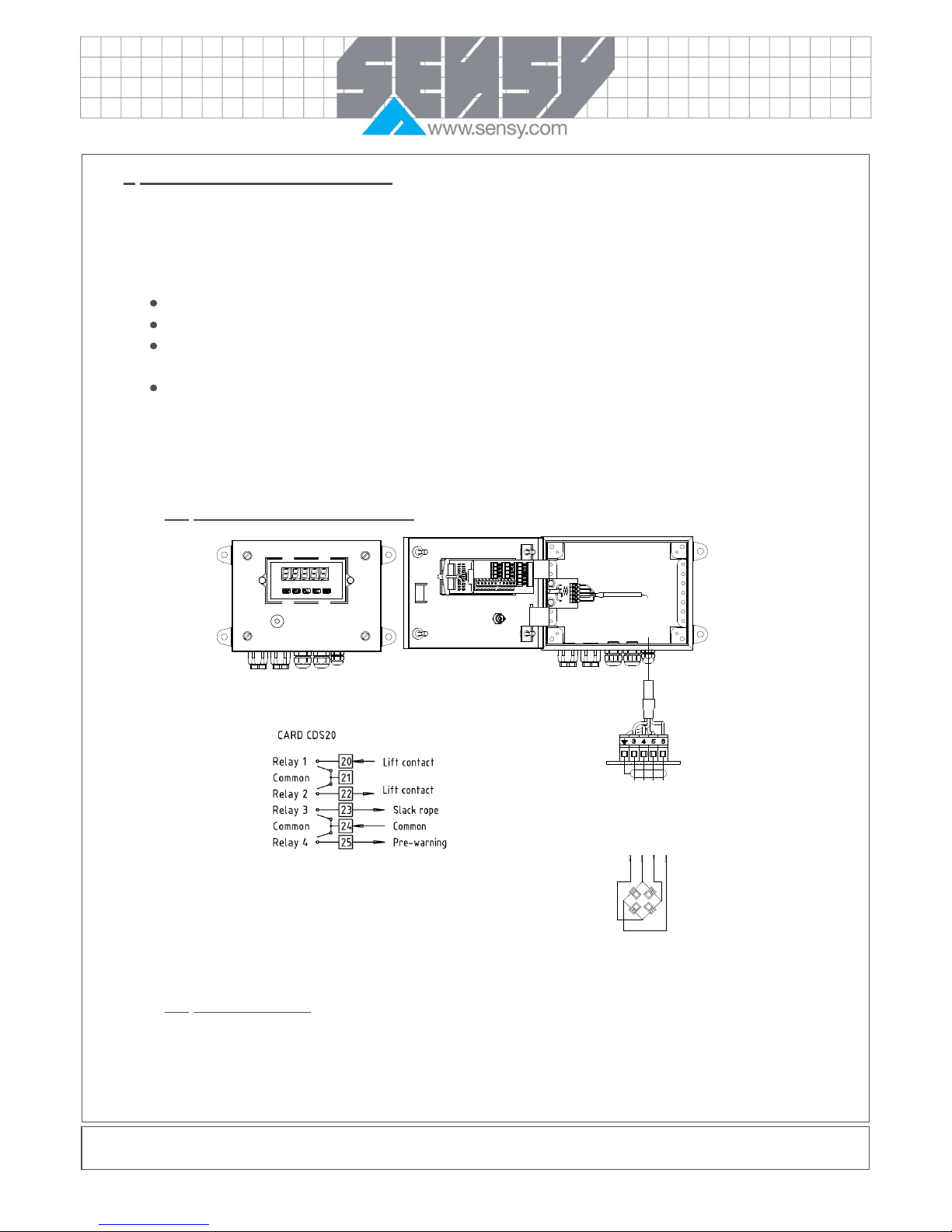
CARD CDC20 (RS232) : PAX’s option card: RS232 Serial communication
- Version RS232
- “Half duplex” communication interface
- Screw terminals or connector
CARD CDC50 (Profibus) : PAX’s option card: Profibus communication
- Transmission of data input/output: up to 84 bytes input/output
- Avalable communication speed : 9,6 KB to 12MB with automatic speed detection
CARD CDL (Analogue) : PAX’s option card: Analogue output
- 0-20 mA, 4-20 mA, or 0-10 VDC
- Resolution 1/3500
CARD CDS (Set point) : PAX’s option card: Relay output
- 2 versions : 2 or 4 relais
- Open connector in « sinking » or « sourcing » mode
Femelle
PAX
 Loading...