

Page 1
1 of 2
INSTALLATION INSTRUCTIONS
Invensys RadioRead
T
Model 510
MPORTANT
I
The following information contains installation instructions for the
Invensys RadioRead
nections are the same for both inside and pit set installations. Techniques may be different for the actual MXU placement in each type of
installation.
Note: This installation sheet is only for installation of the RadioRead
MXU. For instructions on installing other AMR devices, please request
and refer to the individual installation instructions for those devices.
ECOMMENDED
R
®
●
SR II
security screw socket with 1/4" nut driver or ratchet wrench
●
3M Scotchlok
●
3M Scotchlok
●
Wire stripper tool
●
Screwdrivers (Phillips and standard blade heads)
●
Power drill and bit (1/4")
●
8 x 1" sheet metal screws
●
1/2" Electrical Metallic Tubing (EMT)
●
Conduit cutting tool
●
Hammer
●
Conduit driver (available from Invensys)
●
Three-conductor solid wire (Invensys specification)
T
Meter Transceiver Unit (MXU). The wiring con-
OOLS
T
®
UY-2 butt connector “gel-caps”
®
E-9Y stepped jaw crimping tool with wire cutter
AND
ATERIALS
M
Meter Transceiver Unit (MXU)
The MXU also requires proper programming of each port to match the
device that is connected to the respective port. Refer to Invensys Programming Manual AMR-988.
NSTALLATION
I
The MXU wiring instructions assume the utility meter with an encoder
register or MultiRead module has been installed and the proper wire
has been run to the MXU installation location. Three-conductor, 22
gauge, solid conductor cable is recommended. (For meter installation,
refer to the installation information included in Invensys meter shipping
cartons.)
1. Using the SR II security socket with ratchet wrench or nut driver,
open the MXU enclosure by removing SR II type security screw.
Bottom part of enclosure will contain the MXU battery and top part
the electronics and connection wires. Connect the three wires from
the encoder register or MultiRead module to the matching color
wires on the MXU and the desired port. If not already done, strip
approximately 2"
wire colors for each unit should be
matching color wire ends –
black
into a UY-2 gel-cap with the color button of gel-cap facing
away. (This provides a better view of wire positions inside the clear
plastic gel-cap enabling the installer to see the wires are completely and properly inserted.)
Note: For the Schlumberger Proread encoder, the color coded
wire connections are not standard – For Proread, connect the
MXU red to Proread black, MXU green to Proread red, and MXU
black to Proread green.
Using gel-cap pliers, squeeze the gel-cap. This will splice the two
wires and release the waterproof gel to seal the connection. The
splice can be checked by pulling gently on the gel-cap while holding the wires to be sure they are tight and secure. Repeat Step 2
instructions for the remaining two wire connections. Repeat connections to a second port, if required.
- W
off outer jacket
IRING
red
to
NSTRUCTIONS
I
of the encoder wire cable. The
green
,
red
, and
red
,
green
to
black
green
. Insert two
, and
black
to
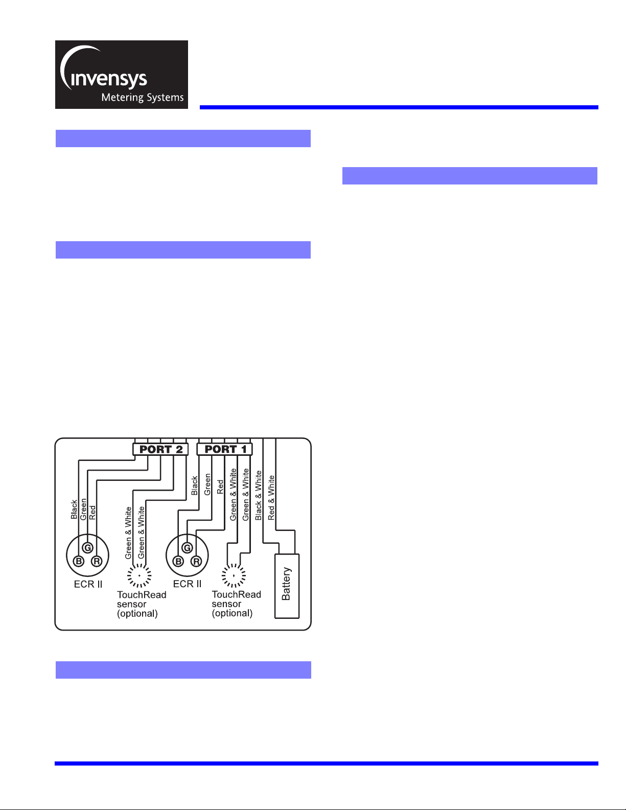
MXU Model 510 - Installation Wiring Diagram
G
ENERAL
The Model 510 MXU incorporates a two-port interface design. Hardwire connections to either port from a compatible utility meter or MultiRead module is the same for each port.
Note: the wiring is different when connecting a Schlumberger
Proread (ARB-VI) encoder to a port.
I
NFORMATION
* If any of the wire connections are not being used they should
be capped at the end with a gel-cap. This is to prevent water
intrusion via wicking through the exposed wire ends. The
green
, and
black
green
with
capped together.
Note: A Schlumberger Proread (ARB VI) register must be connected directly to an MXU port. The Proread register will not work
through a MultiRead module connected to an MXU.
2. Connect the battery to the MXU electronics. Using the gel-cap connecting technique described in Step 2 above, connect the
white stripe
from the MXU electronics. Repeat the procedure for the
white stripe
from the MXU.
Caution: DO NOT cross connect the black and white and red and
white stripe wires of the MXU and battery pack as this may cause
damage to the MXU electronics.
If using the optional TouchRead
skip to Step 4.
3. (Optional) TouchRead
encoders only) – The MXU includes a built-in TouchRead splitter
connection to allow the encoder register to be interrogated by both
RadioRead equipment and a remote TouchRead System sensor.
wires must be gel-capped individually. The
white striped
wire from the battery to the
wire from the battery to the
TouchRead sensor wires can be gel-
red
and
white stripe
black
and
white stripe
®
connection, go to Step 3. If not,
®
Connection (available for Invensys register
red
black
red
and
wire
and
wire
,
Page 2

2 of 2
Wall Mount TouchPad – Using two-conductor or three-conductor
wire cable and gel-caps, connect wires to each of the
white stripe
At the TouchPad connection, connect the same two wires to the
terminal screws on the back of the TouchPad.
Pit-set Mount Sensor – The TouchRead pit-set sensor includes a
factory-sealed three-conductor wire cable. Proper wire connections
are therefore important. To activate the pit-set TouchRead sensor,
use only the
of the cable’s outer jacket must be stripped from its end to access
these wires. Then, using gel-caps, connect the
sensor to one of the
Next, connect the
white stripe wire
ond port if required.
4. Verify MXU operation prior to final assembly: To verify RadioRead
reading, use Radio Frequency Solid State Interrogator (RFSSI) or
Vehicle Transceiver (VXU) to display the register odometer reading(s), register ID number(s), and MXU ID number. (For AMR troubleshooting, refer to bulletin AMR-309.)
-To verify TouchRead reading
to display register odometer reading(s) and register ID number(s).
If MXU does not function, check all wire connections, re-do the
connections or change battery pack. (For complete TouchRead
installation and troubleshooting, see installation bulletins: TR-728,
TR-997, and TR-998.)
5. After wiring connections are completed and MXU operation is verified, align guides of top and bottom parts of MXU and close, bringing the connection wire(s) out the front side, using the wire passthru guides located on either side of the security screw. Secure the
top and bottom parts of the MXU using the security screw.
MXU M
wires from the MXU.
Note: If three-conductor wire cable is used, the third wire is not
utilized for the TouchRead Connection.
Caution: Be sure there is no bare wire-to-wire contact. (The
TouchRead connection is non-polarity sensitive and will w ork as long
as the same color wires are used at both ends of the connection.
If three-conductor wire is used, be sure the third “dead” wire is not
mistakenly connected at either end.) Repeat the connections for a
second port if required.
red
and
black
wires from the sensor. Approximately 2"
green and white stripe
red wire
from the MXU. Repeat the connections for a sec-
Note: When connecting a Schlumberger Proread (ARB VI) register
directly to an MXU port, the TouchRead splitter feature is not available.
Caution: DO NOT over-tighten security screw.
OUNTING
from the sensor to the other
, use a TouchRead visual reader
NSTRUCTIONS
I
black wire
wires from the MXU.
green
and
from the
green
and
For Wall Mounting: (Indoors and Outdoors)
1. Using MXU mounting bracket, find a convenient location for the
MXU mounting. It is recommended that the MXU be mounted in an
upright position so the top part with the Invensys logo is facing up.
The MXU mounting bracket can be mounted to a wall using screws
or fastened to an object using heavy duty wire ties. Grooves have
been placed in the back of the bracket for mounting on either hor izontal or vertical (existing) pipes.
2. After mounting MXU bracket, snap the MXU (which should already
be wired as noted in the preceding wiring instructions) into the
bracket. Be sure the locating tabs on either side of the MXU have
snapped into position in the mounting bracket.The installation is
now complete.
3. TouchPad Mounting (Optional) – If mounting the MXU outdoors and
a TouchRead TouchP ad connection is to be included, mounting
holes can be drilled in the side of the MXU bracket. Using shor t
screws or plastic rivets, mount the TouchPad to the side of the MXU
bracket.
Caution: When using screws, be sure they do not penetrate the
MXU enclosure when mounting the TouchPad. The TouchPad can
also be mounted in a location away from the MXU. Be sure to use
screws that are designed for and applicable to the mounting surface.
For Pit Set Mounting:
1. Use 1/2” EMT. Select a location for the conduit where the MXU’s
installed position will not interfere with the meter and allow the MXU
to be located as high as possible inside the meter box. The MXU
should be kept approximately 1" from the sides of the meter box
and positioned so the meter register odometer remains visible for
visual confirmation readings. Conduit mounting method calls for
driving a length of conduit into the ground at the bottom of the
meter box. (If the bottom of the meter box does not have an opening sufficient for driving the conduit vertically into the ground below,
a different mounting method may need to be developed.) Place
driver on conduit and strike with hammer, driving conduit downward until it is at the desired height. The correct height should be at
the point the driver is level with the top of the meter box in most
cases. When completely installed, the top of the MXU should be
about 1" below the meter box lid.
2. After installation of conduit, position the opening located in the bottom of MXU over the conduit and press into place. Place meter box
cover (lid) into position. Pit set installation is no w complete.
3. TouchRead Sensor Mounting (Optional) – If installing a TouchRead
pit-set module follow the TR/PL mounting instr uctions on Invensys
bulletin TR-997 for mounting in the meter box lid. Place meter box
cover (lid) into position with the TR/PL sensor in place.
FCC C
NOTE: This equipment has been tested and found to comply with the
limits for a Class B digital device, pursuant to part 15 of the FCC
Rules. These limits are designed to provide reasonable protection
against harmful interference in a residential installation. This equipment generates, uses and can radiate radio frequency energy and, if
not installed and used in accordance with the instructions, may cause
harmful interference to radio communications. However, there is no
guarantee that interference will not occur in a particular installation. If
this equipment does cause harmful interference to radio or television
reception, which can be determined by turning the equipment off and
on, the user is encouraged to try to correct the interference by one or
more of the following measures;
– Reorient or relocate the receiving antenna
– Increase the separation between the equipment and receiver
– Connect the equipment into an outlet on a circuit different from that
to which the receiver is connected
– Consult the dealer or an experienced radio/TV technician
WARNING: No party shall make any modifications or changes to the
MXU Model 510 (the equipment) without the express written consent
of Invensys Metering Systems. Doing so could result in the equipment
becoming non-compliant with the requirements of the Federal Communication Commission Rules CFR47 Part 15 and could void the user’s
authority to operate the equipment.
OMPLIANCE
Invensys Metering Systems
P.O. Box 487
450 N. Gallatin Avenue
Uniontown, PA 15401
1-800-METER-IT
1-800-638-3748
FAX (Direct to Factory)
Local: (724) 439-7729
Toll Free: 1-800-888-2403
Web site: www.ims.invensys.com
select
North American Water
Email: h2oinfo@ims.invensys.com
AUTHORIZED INVENSYS DISTRIBUTOR
 Loading...