


RTM II FlexNet™
Revision 1
DUG-10009-01

ii
Revision Summary
Rev No. Date Description
Rev 1 JULY 2013 Initial release.
Copyright
This document, in whole or in part, (“Document”) includes confidential and proprietary information belonging to Sensus USA Inc. and/or one of
its subsidiaries or affiliates. Unauthorized use, reproduction, disclosure, distribution, or dissemination of this Document is strictly prohibited. No
party may use, reproduce, disclose, distribute, or disseminate this Document for any purpose without express written authorization from Sensus
USA Inc. Any use, reproduction, disclosure, distribution, or dissemination of this Document does not transfer title to, license, or grant any patent, copyright, trademark, or other intellectual property rights. This Document, and any copies or derivatives thereof, must be returned immediately on demand. This Document is subject to any applicable non-disclosure agreement(s). Information in this Document is subject to change
without notice and does not represent a commitment on the part of Sensus.
© Copyright 2013, Sensus. All Rights Reserved.
Sensus and the Sensus logo are registered trademarks of Sensus.
FlexNet and associated logos are trademarks of Sensus and its subsidiaries and affiliates.
RTM II, NaviComm, AutomationControl, and SCADA-Xchange are trademarks of Sensus.
All other brand names may be trademarks of their respective owners.
Sensus
Automation
10147 W. Emerald Street, Suite 100
Boise, ID 83704 USA
1-208-658-1292
www.sensus.com
Email: automation.support@sensus.com
Document: RTM II FlexNet User Guide
Document Number: DUG-10009-01
DUG-10009-01 RTM II FlexNet User Guide

Compliance Statements
Sensus devices are for professional installation only. They are to be serviced by
WARNING
profession
vicing.
al personnel only. This product is NOT for consumer installation or ser-
RADIATION
HAZARD
WARNING
ATTENTION
In order satisfy the FCC RF expo
a separation distance of 20 cm (7.8 inches) or more should be maintained while
operating the Sensus device. To ensure compliance, operations at closer than this
distance is not recommended. This minimum safe distance is required between
personnel and this antenna of this device.
The antenna used for this transmitter must not be co-located in conjunction with
any other antenna or transmitter.
For Class B - Unintentional Radiators:
This equipment has been tested and found to comply with the limits for a Class B
digi
tal device, pursuant to Part 15 of the FCC Rules. These limits are designed to
provide reasonable protection against harmful interference in a residential installation. This equipment generates, uses and can radiate radio frequency energy and,
not installed and used in accordance with the instructions, may cause harmful
if
interference to radio communications. However, there is no guarantee that interference will not occur in a particular installation.
If this equipment does cause harmful interfere
which can be determined by turning the equipment off and on, the user is encouraged to try to correct the interference by one or more of the following measures:
• Reorient or relocate the receiving antenna
• Increase the separation between the equipment and receiver
• Connect the equipment into an outlet on a circuit different from that to which the
receiver is connected
• Consult the dealer or an experienced radio/TV technician for help
sure limit of 1.0 mW/cm2 for transmitting devices,
nce to radio or television reception,
WARNING
ATTENTION
ATTENTION
Document Name Document Number
Hazardous voltages are present: To reduce the risk of electric shock and danger to
al health, follow the instructions.
person
Any modifications made to this device that are not app
the authority granted to the user by the FCC to operate equipment.
ICES-003 Class B Notice-Avis NMBThis Class B digital apparatus complies with Canadian ICES-003.
Cet appareil numerique de la classe B est conforme à la norme NMB-003 du Canada.
003, Classe B
roved by Sensus may void
iv Compliance Statements
WARNING
WARNING
WARNING
WARNING
ATTENTION
When applicable, there is danger of explosion if batte
ries are mishandled or incorrectly replaced. On systems with replaceable batteries, replace only with the same
manufacturer and type or equivalent type recommended per the instructions provided in the product service manual.
Do not disassemble batteries or attempt to
recharge them outside the system. Do
not dispose of batteries in fire.
Dispose of batteries properly in accorda
nce with the manufacturer's instructions
and local regulations.
For products with multiple power cords, all power cords must be disconnected to
completely remove power from the system.
For products that use power cords, not all power cords have the same current ratings. Do not use the power cord provided with your equipment for any other use.
hold extension cords do not have overload protection and are not meant for
House
use with computer systems. Do not use household extension cords with your Sensus product.
Sensus products are designed to be connected only to a grounded main circuit outlet. Do not defeat the plug grounding pin and do not plug these products into a nongrounded main power circuit.
This equipment contains components that can be damaged by electrostatic discharge. To prevent unexpected operation or permanent damage, be sure to connect the ground lug to an earth ground and always touch the ground lug before
touching any components inside the enclosure.
ATTENTION
ATTENTION
This device complies with Industry Canada license-exempt RSS standard(s). Operation is subject to the following two conditio
ns: (1) this device may not cause interference, and (2) this device must accept any interference, including interference
that may cause undesired operation of the device.
Le présent appareil est conforme aux CNR
d'Industrie Canada applicables aux
appareils radio exempts de licence. L'exploitation est autorisée aux deux conditions
suivantes : (1) l'appareil ne doit pas produire de brouillage, et (2) l'utilisateur de
l'appareil doit accepter tout brouillage radioélectrique subi, même si le brouillage
est susceptible d'en compromettre le fonctionnement.
This radio transmitter (identify the device by ce
rtification number, or model number
if Category II) has been approved by Industry Canada to operate with the antenna
types listed below with the maximum permissible gain and required antenna impedance for each antenna type indicated. Antenna types not included in this list, having
ain greater than the maximum gain indicated for that type, are strictly prohibited
a g
for use with this device.
Le présent émetteur radio (identifier le di
spositif par son numéro de certification ou
son numéro de modèle s'il fait partie du matériel de catégorie I) a été approuvé par
Industrie Canada pour fonctionner avec les types d'antenne énumérés ci-dessous
et ayant un gain admissible maximal et l'impédance requise pour chaque type
d'antenne. Les types d'antenne non inclus dans cette liste, ou dont le gain est
supérieur au gain maximal indiqué, sont strictement interdits pour l'exploitation de
l'émetteur.
• Phantom 3dBi
Document Number Document Name

Compliance Statements v
Under Industry Canada regulations, this radio transmitter may only operate using
an antenna of a type and maximum (or lesser) gain approved for the transmitter by
Industry Canada. To reduce potential radio interference to other users, the antenna
type and its gain should be so chosen that the equivalent isotropically radiated
power (e.i.r.p.) is not more than that necessary for successful communication.
ATTENTION
Conformément à la réglementation d'Industrie
peut fonctionner avec une antenne d'un type et d'un gain maximal (ou inférieur)
Canada, le présent émetteur radio
approuvé pour l'émetteur par Industrie Canada. Dans le but de réduire les risques
de brouillage radioélectrique à l'intention des autres utilisateurs, il faut choisir le
type d'antenne et son gain de sorte que la puissance isotrope rayonnée équivalente (p.i.r.e.) ne dépasse pas l'intensité néce
ssaire à l'établissement d'une com-
munication satisfaisante.
Document Name Document Number

vi Compliance Statements
Document Number Document Name

Contents
CHAPTER 1, INTRODUCTION 1
1.1 RTM II Overview .......................................................................................................................................... 2
1.1.1 LED Indications .................................................................................................................................. 3
1.2 How it Works ............................................................................................................................................... 4
1.3 Getting Started ............................................................................................................................................ 5
CHAPTER 2, COMMISSIONING DEVICES ON AUTOMATIONCONTROL 7
HAPTER 3, INSTALLING THE RTM II 9
C
3.1 Before You Begin ........................................................................................................................................ 9
3.2 Testing the Receiver Strength ................................................................................................................... 10
3.2.1 Testing Locally with Automation Device Configurator ......................................................................10
3.2.2 Logging In ........................................................................................................................................ 11
3.3 Troubleshooting Radio Communications ................................................................................................... 13
CHAPTER 4, INTRODUCTION TO AUTOMATIONCONTROL 15
4.1 Getting Started with AutomationControl .................................................................................................... 15
4.2 Device History ........................................................................................................................................... 19
4.3 Other AutomationControl Features ............................................................................................................ 20
APPENDIX A, BASIC INTEGRATION GUIDELINES 21
A.1 What You Need ......................................................................................................................................... 21
A.2 Mount the RTM II ...................................................................................................................................... 21
A.3 Connect RTM II to Antenna ....................................................................................................................... 23
A.4 Connect RTM II to IED .............................................................................................................................. 23
A.4.1 RS-232 Communications ................................................................................................................. 23
A.4.2 Half Duplex (2-wire) RS-485 Communications ................................................................................ 24
A.4.3 Full Duplex (4-wire) RS-485 Communications ................................................................................. 24
A.5 Connect 10-29 VDC Power to RTM II ....................................................................................................... 24
A.6 Program Correct Settings into RTM II/IED ................................................................................................ 25
A.6.1 IED ................................................................................................................................................... 25
A.6.2 RTM II .............................................................................................................................................. 25
A.7 Connector Pin Specifications .................................................................................................................... 26
APPENDIX B, BASIC TROUBLESHOOTING 29
B.1 RTM II Session is Offline ........................................................................................................................... 29
B.2 Radio Communication Issues ................................................................................................................... 29
B.3 Unable to See Point Data .......................................................................................................................... 30
RTM II FlexNet User Guide DUG-10009-01

viii Contents
APPENDIX C, HARDWARE SPECIFICATIONS 31
C.1 Processor .................................................................................................................................................. 31
C.2 Communications ....................................................................................................................................... 31
C.2.1 Ports ................................................................................................................................................ 31
C.2.2 FlexNet Network .............................................................................................................................. 31
C.3 Enclosure .................................................................................................................................................. 32
C.4 Operating Power ....................................................................................................................................... 32
C.5 Environmental Data .................................................................................................................................. 32
DUG-10009-01 RTM II FlexNet User Guide

1 Introduction
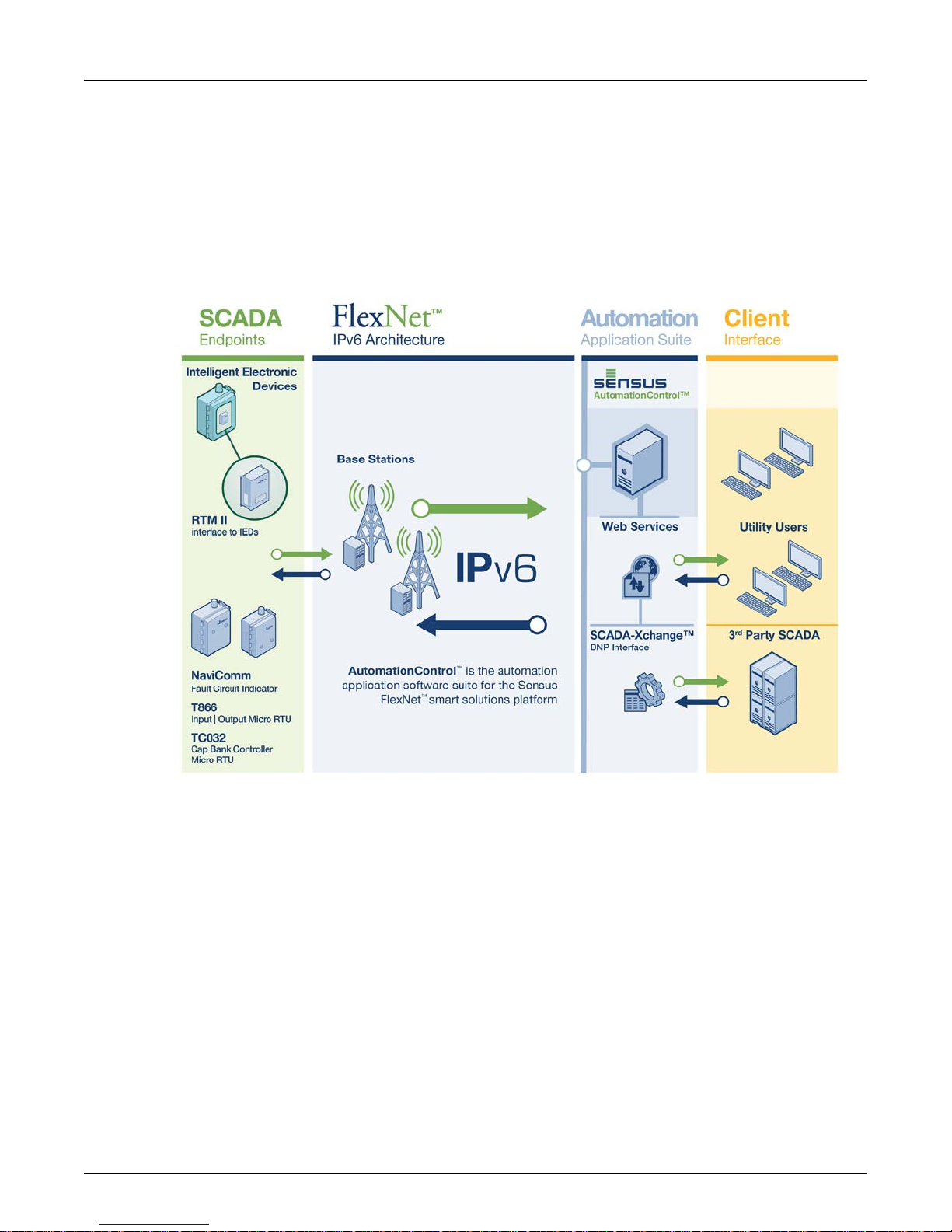
The Sensus Automation Remote Telemetry Module™ (RTM II) is a cost-effective communication solution
for remote monitoring and control of Intelligent Electronic Devices (IEDs) that control electric distribution
system assets such as reclosers, switches, capacitor banks, breakers, voltage regulators, and meters.
RTM II devices can be remotely configured, monitored, and controlled through the secure Sensus
AutomationControl™ Web application using any standard PC. The RTM II includes serial connections, a
USB configuration port, and easy profile management through the AutomationControl software. The
RTM II communicates using the Sensus FlexNet® pr
The multi-address RTM II communicates with any IED that supports DNP3 or Modbus protocols. Models
with FlexNet rad
devices can be installed on any FlexNet system using the latest Automation Network Interface software.
FlexNet models incorporate all of the standard FlexNet system security features.
ios communicate using packet data over the Sensus FlexNet private networks. The
ivate networks.
The devices are ideally suited for Smart Grid distributio
capacitor banks, distribution switches, faulted circuit indicators, voltage regulators, distributed
generation, load control, and small substations.
Figure 1-1: RTM II
n automation applications such as reclosers,
RTM II FlexNet User Guide DUG-10009-01
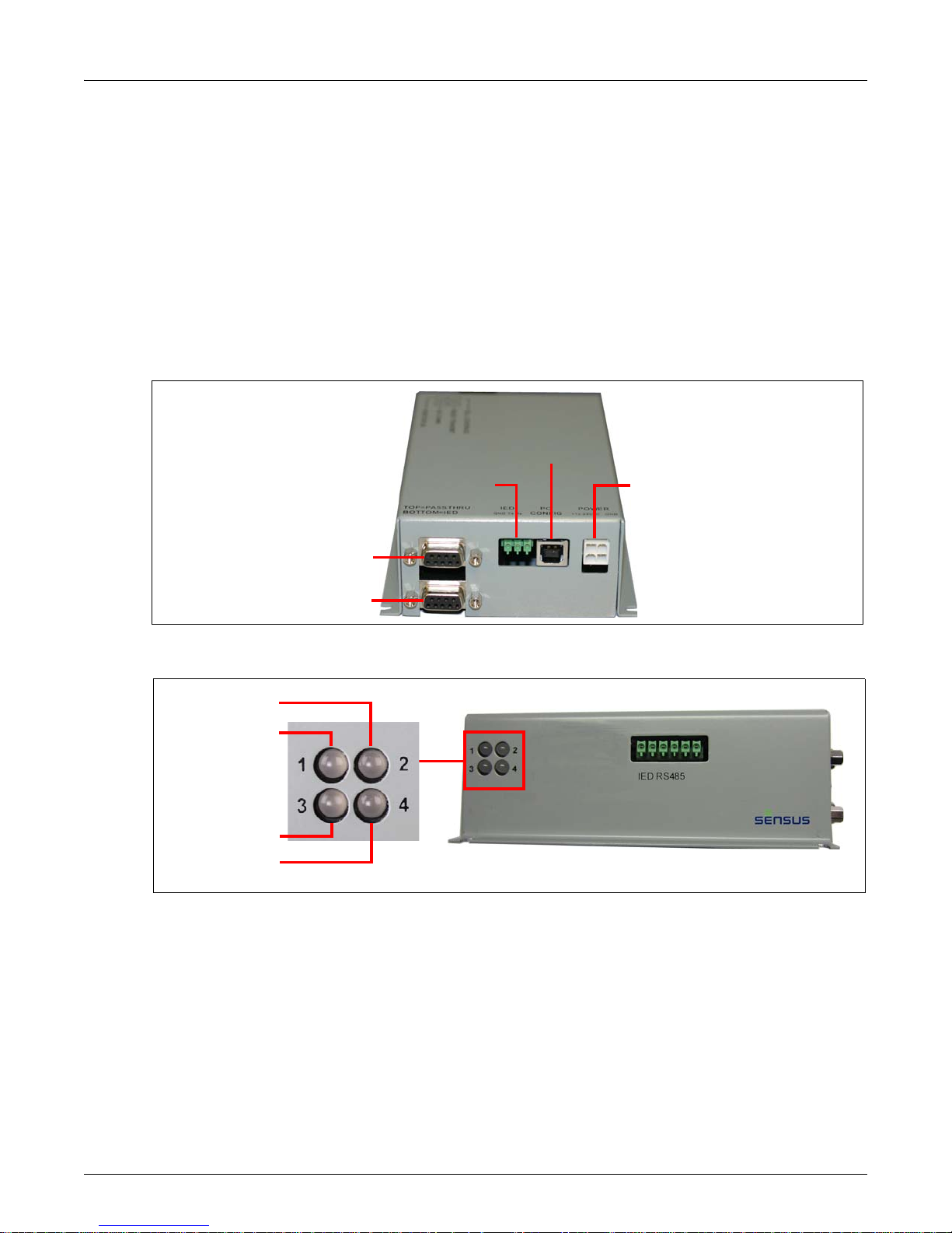
2 Chapter 1: Introduction
Pass Through Port
IED Port
PC Port
IED Terminal DC Power
Radio Transmit
IED Comm
Radio Coverage
RTM Status
1.1 RTM II Overview
The RTM II uses the radio network to enable communications between IEDs with supported protocols
and Sensus AutomationControl™. When it receives data from the RTM II, AutomationControl displays
the data immediately. Alternatively, the customer can use Sensus Automation’s DNP SCADA-Xchange™
software, which uses a secure TCP/IP connection to transfer the DNP3 data directly to the utility's
SCADA system.
Most newer generation Remote Termina
l Units (RTUs) and IEDs use the standard DNP3 communication
protocol to communicate with utility SCADA systems. The RTM II also provides a Modbus interface to the
many IEDs and RTUs that support this protocol.
The RTM II connects to an IED such as a recloser, voltag
e regulator, or capacitor bank controller through
an RS-232 serial port or an optional RS-485 serial port. The RTM II can either be installed as a
communications board within the IED enclosure or externally in its own weatherproof enclosure.
Figure 1-2: RTM II Bottom View
Figure 1-3: RTM II Status LEDs
DUG-10009-01 RTM II FlexNet User Guide

Chapter 1: Introduction 3
1.1.1 LED Indications
(see Figure 1-3)
LED Indicator Description
1 - Radio Transmit
2 - IED Comm
3 - FlexNet Radio
Coverage
4 - RTM Status
Blinking Green The RTM II is sending data to AutomationControl.
Blinking Red The RTM II is receiving data from AutomationControl.
Green Data being sent to the IED.
Red Data being received from the IED.
Solid Green Successful power on (power on call was received), the
Signal to Noise Ratio (SNR) is greater than 15.
Blinking Green SNR is between 7 and 14.
Off SNR is less than 6 or there is no communication from
AutomationControl.
Blinking Green The RTM II is functioning normally.
On or Off There is a serious internal problem with the RTM II. Try
isconnecting it from power and then powering it back up.
d
If this LED remains off, contact Sensus Automation
Technical Support.
RTM II FlexNet User Guide DUG-10009-01
4 Chapter 1: Introduction
1.2 How it Works
The RTM II is programmed with a profile detailing the relevant points on the IED as well as how the user
wants the data to be reported. The RTM II accepts DNP unsolicited report-by-exception as well as
constantly polling the IED to get the latest data. When it discovers a reportable event, for example a
binary input that has changed state, it initiates a report over the radio network to AutomationControl.
Here, the data is validated and processed for distribution to the end user. In addition, control and
configuration information can be sent from the end user back to the RTM II.
DUG-10009-01 RTM II FlexNet User Guide

Chapter 1: Introduction 5
1.3 Getting Started
Setting up an RTM II is a three-step process.
1. Set
2. Atta
3. Ver
up the RTM II using AutomationControl.
◦ Import t
◦ Assign a profile to the device.
ch the device to the IED via the serial port and apply power (+10 to +29 VDC). The RTM II
FlexNet Integration Guide gives complete instructions for installing the RTM II.
Note: If your application does not come with an integration guide, see Basic Integration
ify communications remotely using AutomationControl or locally using the Sensus Automation
Device Configurator utility.
This manual provides the information you need to ge
installing the device, and an introduction to AutomationControl™.
he device to AutomationControl.
Guidelines
on page 21 for basic integration instructions.
t started, including commissioning the RTM II,
RTM II FlexNet User Guide DUG-10009-01

6 Chapter 1: Introduction
DUG-10009-01 RTM II FlexNet User Guide

2 Commissioning Devices on AutomationControl
The RTM II arrives from the factory with default radio settings so it can communicate successfully with
AutomationControl. Commissioning an RTM II involves the following tasks in the order listed.
• Import the device into the system
• Create IED definitions
• Establish report intervals
• Create profiles
• Define sessions, assign profile to session
• Update Configuration Settings
• Update Firmware
For detailed explanations and step-by-step instruction s, refer to “Commissioning Devices” in th e
AutomationControl User Guide or Help.
RTM II FlexNet User Guide DUG-10009-01

8 Chapter 2: Commissioning Devices on AutomationControl
DUG-10009-01 RTM II FlexNet User Guide

3 Installing the RTM II
The RTM II can be purchased either as a communications module that is installed within the IED
enclosure or pre-installed in its own weatherproof enclosure. Follow the instructions in the RTM II
FlexNet Integration Guide to install the RTM II in your specific IED.
If your application does not come with an integration guide, see Basic Integration Guidelines
for basic integration instructions.
3.1 Before You Begin
The Automation Device Configurator software comes with your integration kit. Install the software on your
PC.
You will need to connect the device to
installed. You can use a standard USB 2.0 cable with connector type A to connector type B like Belkin
part F3U154 (available at most computer or office supply stores) as shown in the example below.
on page 21
the PC that has the Automation Device Configurator software
Figure 3-1: Standard USB 2.0 Cable to Connect a PC and the Sensus Device
RTM II FlexNet User Guide DUG-10009-01

10 Chapter 3: Installing the RTM II
Pass Through Port
IED Port
PC Port
IED Terminal DC Pow-
3.2 Testing the Receiver Strength
After selecting an installation location and powering up the RTM II, it is a good idea to test the device’s
ability to transmit and receive. The device must be connected to power and an antenna attached in order
to carry out this test. You can check the radio strength locally using the Sensus Automation Device
Configurator software. Once the RTM II has been installed and commissioned, you can check the radio
strength remotely using AutomationControl.
3.2.1 Testing Locally with Automation Device Configurator
Make sure the PC has the Automation Device Configurator software installed.
Connect the device to the PC
1. Using a standard USB 2.0 cable with Type A to Type B connectors shown in Figure 3-1, insert the
cable into the PC Port on the bottom of the device.
2. Using the USB port, connect the cable to the PC that has the Automation Device Configurator
software installed.
3. Afte
r physically connecting a PC to the Sensus device, follow the next steps to log in.
DUG-10009-01 RTM II FlexNet User Guide

Chapter 3: Installing the RTM II 11
3.2.2 Logging In
Use your computer's Device Manager utility to identify which COM port the Sensus device is using, and
then connect to the device and log in.
Identify the correct COM port
1. Use the appropriate procedure for your Windows® operating system to open Device Manager.
2. Expa
nd Ports, and wait for Device Manager to show the COM port number for the Sensus device.
This is the COM port you will select when you log in to Automation Device Configurator. For
example:
Log in to Automation Device Configurator
1. Open the Automation Device Configurator software.
2. Sele
3. Wa
4. Type
ct the COM port you identified in the previous steps and choose Connect.
it until you see “Ready” in the login window. If you see an error message in this window, verify
that you have selected the correct COM port. Once the device is connected, you can log in.
the password provided to you and choose Login.
The Device Dashboard page shows the current st
configuration settings, power information, and signal strength. The system automatically refreshes all
atus of the connected device including
RTM II FlexNet User Guide DUG-10009-01

12 Chapter 3: Installing the RTM II
statuses every three minutes. You can change how often this information is updated by checking
Continual Refresh, which updates data every 3 seconds, or by manually refreshing as needed.
◦ Green = Good. Communication to AutomationControl and/or the IEDs are working and the
device configuration has been recognized and processed at the headend system.
◦ Red = Bad. Something needs attention. If the following items are red, try the solutions in the
order listed.
1. Radio Communications with AutomationControl: The Sensus device is not
communicating with the headend through the base station. Go to the Radio tab and verify
that radio settings are correct. See
Troubleshooting Radio Communications on page 13.
2. Configuration Loaded from AutomationControl: A profile likely has not been configured
for the device at the headend, so a system administrator needs to do this before you can
continue.
3. IED [N] Online Status: There is no communication to the IED. Verify that the IED is
connected, powered on, in online mode, and that it is configured to match the settings on the
Sensus device. If there is still no communication, the configuration settings might need to be
adjusted in AutomationControl.
“Last Signal Strength” shows the most recent transmitted and received signal strength.
◦ Green = Excellent: Greater than 11
◦ Yellow = Moderate: 7 - 11
◦ Red = Weak: 6 or below
To improve a moderate or weak FlexNet radio signal, verify all antenna and antenna cable
connections, raise the antenna, or reposition the antenna.
DUG-10009-01 RTM II FlexNet User Guide

Chapter 3: Installing the RTM II 13
3.3 Troubleshooting Radio Communications
In the Automation Device Configurator software, click the Radio tab to verify that the correct radio
settings are entered for your Sensus Automation FlexNet channels.
If the following items are red, try the solution listed.
◦ Loaded the radio parameters from: Shows the location of the file containing the radio settings.
If the file cannot be found, contact your system administrator or Sensus Automation Technical
Support.
◦ Radio Communications with AutomationControl: The Sensus device is not communicating
with AutomationControl through the base station. Verify these communication settings are
correct.
◦ Send Radio Settings - Restart: If this button is red, it means no radio parameters are loaded.
Contact your system administrator for the correct settings.
You may need to check with Sensus Automation Technical Support that your Automation Network
Interface and FlexNet Base Station are linked and routed.
◦ Power cycle the device and wait 5 minutes for radio communication to stabilize. If you are still
unsuccessful, contact Sensus Automation Technical Support.
Note: For more detailed information about using the Automation
its Help.
Device Configurator utility, refer to
RTM II FlexNet User Guide DUG-10009-01

14 Chapter 3: Installing the RTM II
DUG-10009-01 RTM II FlexNet User Guide

4 Introduction to AutomationControl
AutomationControl™ provides access to the data from your Sensus Automation devices 24 hours a day,
seven days a week, from any computer that has access to the Internet. Use AutomationControl to set up
all monitoring and control functions, to set up automatic event notifications, and to remotely control the
equipment connected to the RTM II.
The following sections provide a brief overview of
For detailed descriptions and step-by-step instructions for using the software, refer to the
Automation Control User Guide or application Help.
some of AutomationControl’s basic functions.
4.1 Getting Started with AutomationControl
To log in to your account, you need the user name and password Sensus provided to you.
Log in to your secure account
1. Open AutomationControl.
2. Type
your user name and password and press Enter (or choose Log In).
RTM II FlexNet User Guide DUG-10009-01

16 Chapter 4: Introduction to AutomationControl
The Devices page shows a list of active devices by:
◦ Device ID and description
◦ The associated IED
◦ Any off-normal conditions
◦ Device and IED status
◦ The existing signal strength
◦ A timestamp for the most recent communication from the device
If a profile has not yet been transferred or assigned to a unit-session, it is shown as IED Name
(Pending).
DUG-10009-01 RTM II FlexNet User Guide

Chapter 4: Introduction to AutomationControl 17
3. Click a Device ID to see the real-time status of that device on the Device Status page.
Data is updated automatically, and you can also click your browser's Refresh button at any time to
update the data manually.
Feature Description
Top Banner Contains the device ID and physical location, the profile currently assigned to
Point Data Based on the device profile, this list shows the last reported binary input,
Location Geographic location by latitude and longitude, and any other customized
RTM II FlexNet User Guide DUG-10009-01
the device, product type (RTM II, RTM II+, TC032, T866, NaviComm), current
status of the device, the current status of the associated IED, signal strength,
and encryption status.
Signal Strength Indicator Colors and Values
• Green = Excellent: Greater than 11
• Yellow = Moderate: 7 - 11
• Red = Weak: 6 or below
analog input, and analog output values and their timestamp. It also shows any
values in an off-normal state.
To sort data, click a column heading.
location information for the device.

18 Chapter 4: Introduction to AutomationControl
Feature Description
Device Information Lists details about the device, including:
• Last applied firmware
• Timestamp for the last communication received
• Timestamp for the most recent configuration update
• Status of automatic key rotation (used with encryption)
• FlexNet radio ID
Route Information A base station routing summary for the device is shown here. This list includes
all base stations the device has communicated with. Rank is based on the
score. The score is factored from the number of successful outbound
commands to that base station, the number of failed outbound commands to
that base station, and the last ten averaged SNRs. Click a column heading to
sort information.
DUG-10009-01 RTM II FlexNet User Guide

Chapter 4: Introduction to AutomationControl 19
4.2 Device History
Device History lets you see historical device reporting activity. You can select a date/time range, perform
a full-text search, filter the number of results, and move between pages. To protect resources when the
system finds and returns a lot of data, it might only return limited results.
• Select an option—Report History or
default, “Now,” which is the current time), and choose View Report.
• Choose an item in the list to see more details in th
data, commands, responses, and other DNP objects in a report.
Point Data History—select a date/time range (or leave as the
e report. This shows detailed information on all
Report History shows:
• The origin of each report (from the device or from AutomationControl)
• Timestamps for the time the repor
device
• DNP function description within the report (refer to the sta
details)
◦ Unsolicited
◦ Solicited: Any request or command from AutomationControl.
◦ Read
◦ Direct Operate: Sends a command directly to the IED in one step.
◦ Select Before Operate: Adds a slight amount of latency since it is a two-step command (1-Select,
2-Operate).
• Response reason
◦ Nor
◦ Time Scheduled Report: A customized report set up to respond at a user-specified time.
◦ Session Offline: The Sensus device and the IED are not communicating.
◦ Session Online: The Sensus device and the IED are communicating successfully.
◦ Any errors detected in the report
mal: Any type of changed data or response to a request.
: Anything AutomationControl did not request from the device.
t was sent or received by AutomationControl and sent by the
ndard DNP documentation for more
RTM II FlexNet User Guide DUG-10009-01

20 Chapter 4: Introduction to AutomationControl
• SSI: Signal strength from the base station. A list of SSI ranges.
• Number of inbound retries
Point Data History lets
reported.
you see activity of point data, which includes an entry for each point value
Point Data History shows:
• Point type, index, label, and value
• Scaled point value definitions
• Units of measure
• Any off-normal conditions
•Flags
• Timestamps for when the point data
Time)
was reported (Occurred At) and when it was updated (Device
4.3 Other AutomationControl Features
For more information on the following AutomationControl features, see the AutomationControl User
Guide or application Help.
• Setting up SCADA-Xchange
DUG-10009-01 RTM II FlexNet User Guide

Appendix A Basic Integration Guidelines
If your application does not come with a specific integration guide, follow the general instructions in this
section.
1. Make sure you have all needed materials
2. Commission the RTM II on AutomationControl
3. Mount the RTM II
4. Connect the RTM II to the antenna
5. Connect the RTM II to the IED
6. Connect 10-29 VDC Power to the RTM II
A.1 What You Need
• Drill with 1/8-inch bit
• 4 bolt/nut pairs to secure the RTM II to the IED enclosure. We recommend 4-40 x 3/8-inch pan bolt
and Size 4 kepnuts.
• Appropriate cable/antenna combination
• Male-female straight-through serial cable or a null-modem cable/adapter
• 10-29 VDC power supply and/or battery backup
A.2 Mount the RTM II
Some integrations come with a mounting plate. If you have an integration that you would like to have a
plate developed for, please contact Sensus Automation Technical Support. Otherwise, the RTM II can be
mounted to any available space in the IED cabinet.
• We do not recommend installing the RTM II on the exterior wall of the enclosure since it is difficult to
make the holes weather tight.
• Orientation is not critical, but it is best to position and mount the RTM II where a user can see the four
LED lights.
Mount the RTM II
1. Check that there is enough space, and then mark and drill holes to mount the RTM II.
RTM II FlexNet User Guide DUG-10009-01

22 Appendix A: Basic Integration Guidelines
RTM II Mounting Hole
Footprint
2. Once your holes are drilled, use 4 bolt/nut pairs to secure the RTM II to the IED enclosure.
We recommend 4-40 x 3/8-inch pan bolt and Size 4 kepnuts.
Below are drawings of the RTM II dimensions, connector locations, and a drill hole diagram.
DUG-10009-01 RTM II FlexNet User Guide

Appendix A: Basic Integration Guidelines 23
Figure A-1: Sample RTM II Mounting and Connections
A.3 Connect RTM II to Antenna
The RTM II should be connected to an antenna located on or fully outside the IED enclosure. An antenna
internal to the enclosure may produce poor radio strength.
You will need an appropriate cable/antenna combination. The RTM II has an SMA type cable connector.
Contact your sales representative for some possible cable/antenna combinations or to place an order.
A.4 Connect RTM II to IED
For help with a specific IED, please contact Sensus Automation Technical Support.
A.4.1 RS-232 Communications
To connect an RTM II to an IED with a RS-232 serial port, you will need a serial cable to connect
between the RTM II and the IED. Each IED is different but it is most likely that you will need a malefemale straight-through serial cable. If this does not result in communications, you may need a nullmodem cable/adapter for your integration.
RTM II FlexNet User Guide DUG-10009-01

24 Appendix A: Basic Integration Guidelines
A.4.2 Half Duplex (2-wire) RS-485 Communications
To connect an RTM II with optional RS-485 port to an IED with half duplex RS-485, place a jumper on the
RTM II RS-485 port between TX+ and RX+ and another jumper between TX- and RX-. Use the wiring
diagram below.
RTM II IED1 IED2+
TX+/RX+ + +
TX-/RX- - -
Gnd Gnd Gnd
A.4.3 Full Duplex (4-wire) RS-485 Communications
To connect an RTM II with optional RS-485 port to an IED with full duplex RS-485, use the wiring
diagram below.
RTM II IED1 IED2+
TX+ RX+ RX+
TX- RX- RX-
RX+ TX+ TX+
RX- TX- TX-
Gnd Gnd Gnd
A.5 Connect 10-29 VDC Power to RTM II
The RTM II needs 10-29 VDC, typically 170mA at 12 VDC, with a maximum of 0.6A. If you need data
reported, and the option to issue commands during a power outage, the RTM II power supply will need
battery backup. If you only have 120 VAC available, consider using an RTM II 120V model with built-in
battery backup.
Many IEDs have options for a radio power supply outpu
backup. Once you have located the power supply, hook the red power cable lead to +10 to +29 VDC and
the black power cable lead to 0 VDC.
t, generally between 10-29 volts, with battery
Figure A-2: Cable Connections
DUG-10009-01 RTM II FlexNet User Guide

Appendix A: Basic Integration Guidelines 25
A.6 Program Correct Settings into RTM II/IED
The RTM II and IED must be programmed to speak to each other. For the parameters that must match
between IED and RTM II, you may change whichever is most convenient to match the other. The RTM
is set up using AutomationControl. Ensure the following for each device.
A.6.1 IED
Parameter Rule
II
Serial Information (Baud Rate, Data Bits,
Parity, Stop Bits)
IED Outstation (Slave) Address Must match IED Address in the correct RTM II profile session.
Master Address (DNP3.0 only) Not all IEDs have a setting for or care about the Master address, but
Protocol Setup Some IEDs require that their Protocol be set up before use. Ensure
Port Setup Some IEDs need specific ports to be enabled for a certain protocol.
A.6.2 RTM II
Serial Information (Baud Rate, Data Bits,
Parity, Stop Bits)*
IED Outstation (Slave) Address* This is set up for each profile session. Generally, each session will
Master Address (DNP3 only)* Not all IEDs have a setting for or care about the Master address, but
Must match RTM II Setup.
if your session is offline, this is a parameter to look for.
that the point mapping inside the IED matches the point mapping
inside the RTM II profile.
Ensure that the port you are using is enabled for the correct settings.
Parameter Rule
Must match IED Setup. The default is 9600, 8, N, 1. Available Baud
Rates are: 100, 150, 300, 600, 1200, 2400, 4800, 9600, 19200,
38400 & 115200
need a unique IED address. This must match the IED address.
if it does, this must match the IED's Master address.
Protocol The RTM II supports DNP3 and Modbus protocols.
Profile The profile loaded into the RTM II must match the point mapping in
FlexNet Settings* These settings must match the settings of your FlexNet Base
* Indicates settings that can be changed locally.
RTM II FlexNet User Guide DUG-10009-01
the IED.
Station. Use the Sensus Automation Device Configurator utility and
go to the Radio menu. Make necessary changes.

26 Appendix A: Basic Integration Guidelines
A.7 Connector Pin Specifications
RS-232 Ports (IED and PassThru)
9-Pin Connector Terminal Block
Pin Description Pin Description
1 Not Used 1 Tx
2 Tx 2 Rx
3 Rx 3 Ground
4 Tied to 6
5 Ground
6 Tied to 4
7 Tied to 8
8 Tied to 7
9 Not Used
RS-485 (Optional Port) Configuration and Setup
Terminal Block
Pin Description
1 Rx+
2 Rx-
3 Tx+
4 Tx-
5 Ter m
6 Gnd
DUG-10009-01 RTM II FlexNet User Guide

Appendix A: Basic Integration Guidelines 27
Pull Up/Pull Down Resistors
If you are using RS-485 for multidrop communications, or if it is in an electrically noisy environment, you
might need to use pull up and pull down resistors. To do this, use two (2) 4.7K Ohm resistors to jumper
Rx+ to Term and Rx- to Gnd.
Terminating Resistors
For long runs or high Baud rates, it may be necessary to use a terminating resistor. This is generally not
needed.
Half-Duplex
Install a 120 Ohm resistor between the + and - signals.
Full-Duplex
On the master, install a 120 Ohm resistor between the Rx+ and Rx- signals. On the farthest slave
device, install a 120 Ohm resistor between the Rx+ and Rx- signals.
Data Line Polarity
For communication to work, the polarity of the two RS-485 lines must be correct. Always connect +
signals to + signals and - signals to - signals. If your equipment uses the naming convention of RDA/
RDB/TDA/TDB, the As will either be + or - and no convention is strictly followed. Try A with the + signal
first but if that does not work, try switching to A with the - signals.
RTM II FlexNet User Guide DUG-10009-01

28 Appendix A: Basic Integration Guidelines
DUG-10009-01 RTM II FlexNet User Guide

Appendix B Basic Troubleshooting
Pass Through Port
IED Port
PC Port
IED Terminal DC Power
Follow the guidelines below to resolve common issues with your RTM II. If you cannot resolve the
problem, call Sensus Automation Technical Support at 208-658-1292, Ext. 21, or send an email to
automation.support@sensus.com.
B.1 RTM II Session is Offline
A DNP Session Offline message means that the RTM II is not able to communicate with the IED. Check
the following.
• Phy
• DNP Parameters: Verify that the Master/Outstation Address settings match. If these settings for the
• Ser
• IED Conf
sical Connections: Verify the IED is connected to the device using the correct communication
port. Connect the IED to the bottom COM port on the device.
device and the IED do not match, communication between the two will not be possible. These can be
changed using AutomationControl.
ial Parameters: The default communication rates for the RTM II are 9600 baud, 8 data bits, 1
stop bit and no parity. These must match the parameters of the IED. These can be changed using
AutomationControl.
iguration: Many IEDs have different protocols available for their ports. Whatever port you
are using for the communication must be configured for the DNP protocol.
B.2 Radio Communication Issues
Verify the device’s ability to transmit and receive. (The device must be connected to power and an
antenna attached in order to carry out this test.) You can check the radio strength using the Automation
Device Configurator utility. See Testing the Receiver Strength
• Verify that the correct radio setting
is a completely new FlexNet installation, you may need to check with Sensus Automation Technical
Support that your Automation Network Interface and FlexNet Base Stations are linked and routed.
• Verify all antenna and antenna cab
• Power cycle the device and wait 5 minutes for radio communication to s
does not improve, contact Sensus Automation Technical Support.
• If you are still unable to send a command or reques
Technical Support.
RTM II FlexNet User Guide DUG-10009-01
on page 10.
s are entered for your Sensus Automation FlexNet channels. If this
le connections, raise the antenna, or reposition the antenna.
t to your device, contact Sensus Automation
tabilize. If the signal strength

30 Appendix B: Basic Troubleshooting
B.3 Unable to See Point Data
If your IED is not reporting data or responding to commands as expected, you may not have the correct
point/rule mapping. Verify that the IED is programmed with the correct parameters and that the RTM II is
loaded with a matching profile. If this is a new RTM II profile, contact your profile administrator or Sensus
Automation Technical Support for assistance.
DUG-10009-01 RTM II FlexNet User Guide

Appendix C Hardware Specifications
C.1 Processor
• Main Processor: 32 bit microcontroller, 72 MHz
• 8 MB non-volatile Flash memory
• 32 MB SDRAM
C.2 Communications
C.2.1 Ports
• USB 2.0 compliant, full speed, local configuration port; Supports MS Windows based local
configuration and test program.
You can use a standard USB 2.0 cable
F3U154 (available at most computer or office supply stores) as shown in the example below.
with connector type A to connector type B like Belkin part
• RS-232 SCADA communications port, DB-9 female and terminal block; Supports DNP 3.0 or
Modbus depending on firmware
• RS-232 Pass Through for IED maintenance port connection, DB-9 female
C.2.2 FlexNet Network
• Two-way - all commands are acknowledged
• Transmit power: 2 W
• Frequency: 900 MHz band, Primary licensed
• 50 Ohm SMA antenna connector
RTM II FlexNet User Guide DUG-10009-01

32 Appendix C: Hardware Specifications
C.3 Enclosure
The standard enclosure is painted steel. Features include:
• NEMA 1 rating
• Integrated mounting flanges
• Gray steel construction
• Dimensions: 5.6"H x 4"W x 1.7"D
• Optional NEMA 3R enclosure with 120 VAC - 12 VDC power supply; 11"H x 8.3"W x 3.3"D; 3 lbs
C.4 Operating Power
• 10-29 VDC, typically 170mA at 12 VDC, with a maximum of 0.6A (< 0.5 sec.)
C.5 Environmental Data
• Operating temperature Range: -40º to +70ºC
• Humidity: 0% to 95% noncondensing
• Surge Suppression: EN61000-4-4 and EN61000-4-5
• Radiated emissions: FCC Part 15 Class B, EN 55022
DUG-10009-01 RTM II FlexNet User Guide

Appendix C: Hardware Specifications 33
RTM II FlexNet User Guide DUG-10009-01

34 Appendix C: Hardware Specifications
DUG-10009-01 RTM II FlexNet User Guide
 Loading...