

Page 1
Operating Instructions
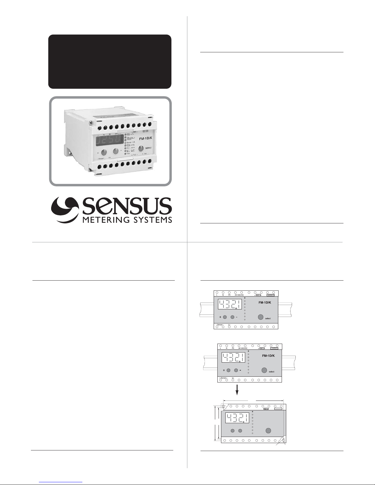
Frequency Converter FM-1D/K
Digital-analogue-converter
and flow rate indicator for water meters
Contents
1. Description
2. Mounting
3. Connection
4. Calibration by hand
5. Protection
6. Test mode
7. Operation
8. Lightning protection
9. Trouble shooting
10. Replacing fuses
1. Description
FM-1D/K is a µP-controlled frequency
converter with display.
It converts pulses into proportional current for flowrate display.
Input from the pulsers are converted to:
• Standardized current
• Pulse totalization
• LED display
2. Mounting
Snap action on
35mm top hat
rail acc. to EN
50022
remove from
top hat rail
Wall mounting
with two screws
M5M4
5060
85
+ Sensor -
U+
N PE 24 VAC/DC
12345678
+
-
+
-
FM-1D/K
select
Page 2

3. Connection
Note:
• max cable cross section is 2.5 mm
2
• check power supply voltage before using
• with 24 VDC operation, the polarity is irrelevant
• Technical Data please see leaflet L S 5100 GB
Safety information
When making the electrical connections, it is
essential to disconnect the FM-1 D/K from the
power supply.
The connection of the FM-1D/K is only allowed by
a specialist in accordance to the common safety
standards.
Connection of 3-wire-sensors
4. Calibration by hand
+ Sensor -
U+
L N PE 24 VAC/DC
12345678
+-
FM-1D/K
select
+
-
Status LEDs
select keychange keys
LED display
Calibration
After connecting the FM-1 D/K needs to be calibrated:
1. Select With the SELECT- button the programming
parameters can be chosen. The status LED indicates
the actual selection.
2. Change By pressing either the (+) or (-) button the
status LED and the first placed digit will flash. With
the (+) and (-) button the settings can be changed.
To activate the second placed digit the SELECT-but
ton must be pressed.
3. Save To save the chosen settings the SELECT-but
ton must be pressed after changing the last right
hand digit.
The settings will not be lost after a power failure.
Setting example
Water meter WPD DN 80
Pulser Opto OD 01 (1 imp = 1 Ltr.)
Current output 0 ... 20 mA
Max. flowrate 0 ... 100 m
3
/h
Pulse output 1 Imp. = 1 m
3
1. Flowrate range
After switching on, the display indicates ”0000.”.
Pressing either the (+) or (-)-button the FM-1 D/K
changes to the programming mode. The left digit of the
display will flash. Set the digit ”0” with the (+) or (-)-button. Pressing the SELECT-button changes to the second digit. As described set the 2.,3.,4. digit and the decimal point.The display should indicate ”0100.”. The possible flowrate range is 0.001 ... 9999. m
3
/h
2. Counter reading
The FM-1 D/K counter reading can be set to match the
counter reading of the water meter. When the upper status LED blinks the first 4 digits can be set and when
Page 3
the lower status LED blinks the last 4 digits can be set.
The setting is identical as described in point 1. The position of the decimal point depends on the output pulse
value ( see point 4)
3. Pulser
The setting of the pulse value of the sensor in litre per
pulse. In this example with 1 litre per pulse the display is
to be set to ”0001.”. The possible input pulse range is
0.001 ... 9999. litres/pulse. After the pulse value programm the signal mode suitable for the connected pulser.
InPu= Opto OD 01-04 without evaluation of the direction
signal
InPb= Opto OD 01-04 with evaluation of the direction signal
InPr= Opto OD 01-04 without direction signal
4. Pulse output
For example to set 1 pulse per m3, the display must indicate ”0001.”. The setting is identical as described in
point 1. The possible output pulse value is 0.001 ...
9999.m
3
. Note ! The output pulse value has to be > to the
input pulse value. At max. flowrate the output pulse rate
must not exceed 1 Hz.
5. Current output
The actual current output range will be indicated at the
display. With the (+) or (-)-button it can be toggled
between 0...20mA and 4...20mA. Pressing the SELECT
button saves the setting.
6. Damping
The damping determines the response time of the current output and the flowrate indication.
If there are no special requirements for the response
time please set damping value ”0004”.
Setting 1 - no damping Setting 14 - max. damping
*) from serial no. 105.000
5. Protection
The FM-1D/K can be protected against unintentional
changes to the setting. In the protect-mode all settings
and measuring values can be displayed. Changing the
values is not possible.
Simultaneously by pressing (+) and (-)-buttons and the
SELECT-button, the present mode will be displayed.
display ”LOC 6”
- device in programming mode,
display ”LOC 8”
- device protected.
With the (+) or (-)-buttons modes can be toggled
between ”LOC 6” and ”LOC 8”. Pressing the SELECT
button saves the setting.
6. Test mode
In the test-mode the digital and ana-
logue output of the FM-1D/K can be
checked on the integral counter and flowrate indicator,
without having a pulser connected to the pulse input.
First the firmware revision will be indicated.
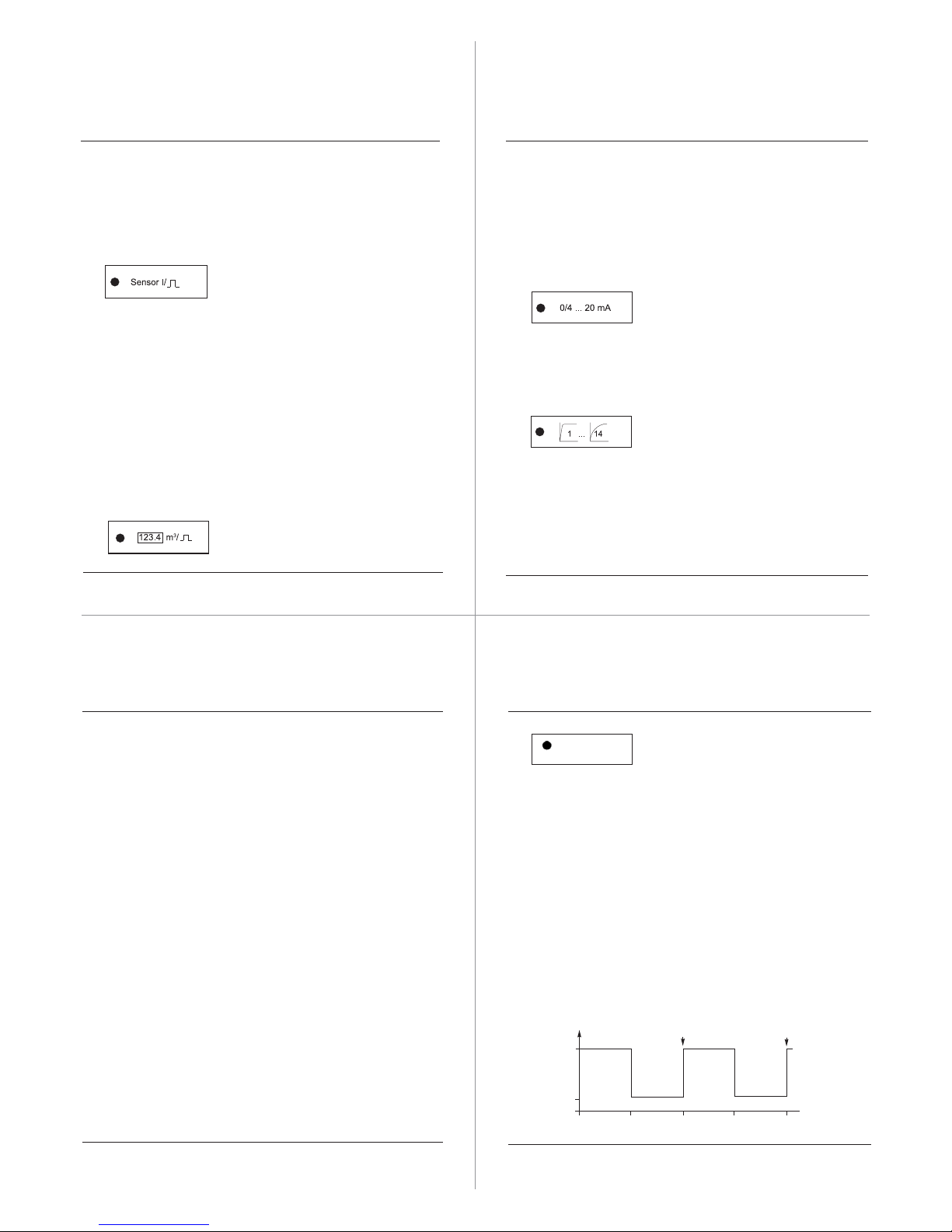
By pressing the (+) or (-)-buttons the test mode starts:
The current output toggles, as indicated on the display,
in a 30 second interval between 0(4) und 20 mA. The
flowrate indicator should alternate between ”0” and full
scale.
At the pulse output terminals a pulse will be generated
every 60 seconds. These pulses will be indicated on
the pulse counter.
Pressing the SELECT-button leaves the test mode and
changes into the standard mode.
Test
I in mA
t in sec.
Pulse
Pulse
30 60 90
20
4
120
Page 4
7. Standard mode
Rapid flashing of all status LED’s indicates incoming
pulses.
The permanently illuminated status LED indicates the
measuring units on the display.
The display can switch between:
• Flowrate indication
At reverse flow direction the display shows “-000” *)
• Counter reading (first 4 digits)
• Counter reading (last 4 digits)
• Pulse value of the pulser input(Sensor)
• Pulse value of the pulse output
• Current output range
• Damping
• Firmware revision (Test)
*) from serial no. 105 000
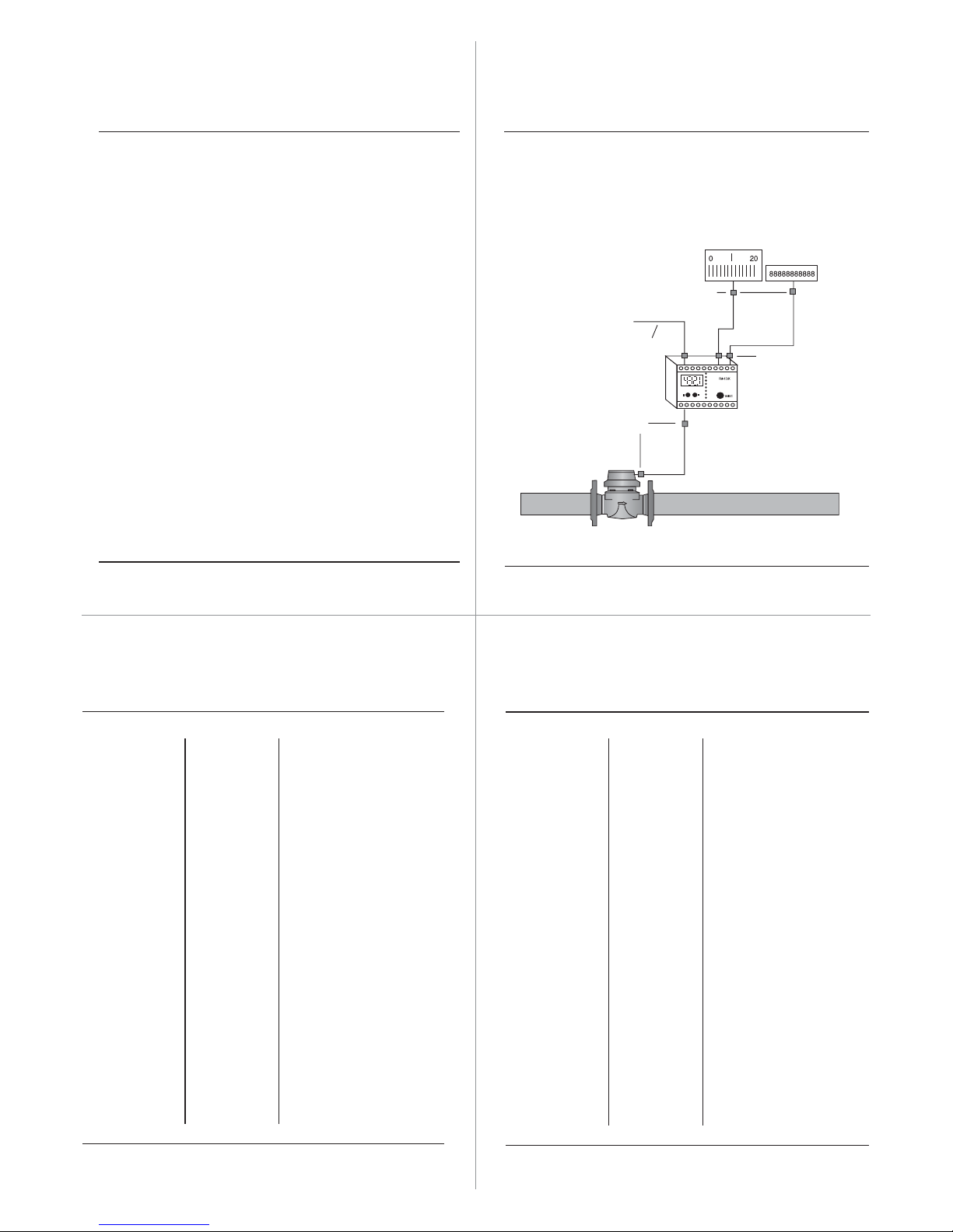
To protect the FM-1D/K from voltage surges caused by
lightning, installation of an adequate lightning protection
device is recommended.
Depending on the situation on site, we recommend the
8. Lightning protection
Lightning protector 48 VDC/AC
230 VAC
Overvoltage protection
Lightning protector
15 VDC
Water meter e.g. WP-Dynamic
with pulser OD
Frequency converter
FM-1D/K
Lightning protector
48 VDC/AC
Max.
20km
Error Symptom Cause
Remedy
9. Trouble Shooting
Status lamps
and LED display not working
No current output but internal
display indicates flowrate
No power
supply
Error in the
current output circuit
Check current output
using the test mode
Check connected indicator.
Check external totalizer
and its power supply
No pulse output
but the internal
display counts
the volume
Error in the
pulse output
circuit
Check pulse output using
the test mode
Check external totalizer
and its power supply
Check supply voltage
For 230V: Check voltage
selector (Pos. 230 V) and
fuse F 91 (200 mA m)
For 24 V: Check fuse F 92
(200 mA m)
Error Symptom Cause
Remedy
Trouble Shooting
Flowrate display
“0“ and no
output pulses
but the water
meter is working and the
pulser is connected.
Error in the
pulse input
circuit.
If status LED’s are flashing acc. to the incoming
pulses:
Check the settings of
FM-1D/K.
If the status LED’s are
not flashing acc. to the
sensor pulses:
Check input. Remove
pulser, shortcircuit the
sensor terminals
(+) and (-) with a wire.
- If status LED’s flash:
Replace pulser.
- If status LED’s don’t
flash: Check fuses F
111 and F 112
(32 mA m).
Page 5
Sensus Metering Systems GmbH Hannover
Meineckestrasse 10, 30880 Laatzen, Germany
D+49 (0) 5102 74 0 F +49 (0) 5102 74 3341
[email protected] www.sensus.com
Error Symptom Cause
Remedy
Trouble Shooting
FM-1D/K refuses programmation
The device is
locked
against programming
Unlock device.
(please see chapter 5,
Protection).
Reading Flowrate is
too high
Check input pulse value.
Increase max. value of
flowrate.
Reading Input fre-
quency higher
than 1 kHz
e.g. caused
by bouncing
Reed pulser
- Check settings
- Exchange pulser
(Opto or inductive)
- Use additional contact
protection relay
Indication
“InPe”
Pulse error - Change pulse signal,
“InPb” or “InPu” for
Opto OD, “InPr” for
Reed RD.
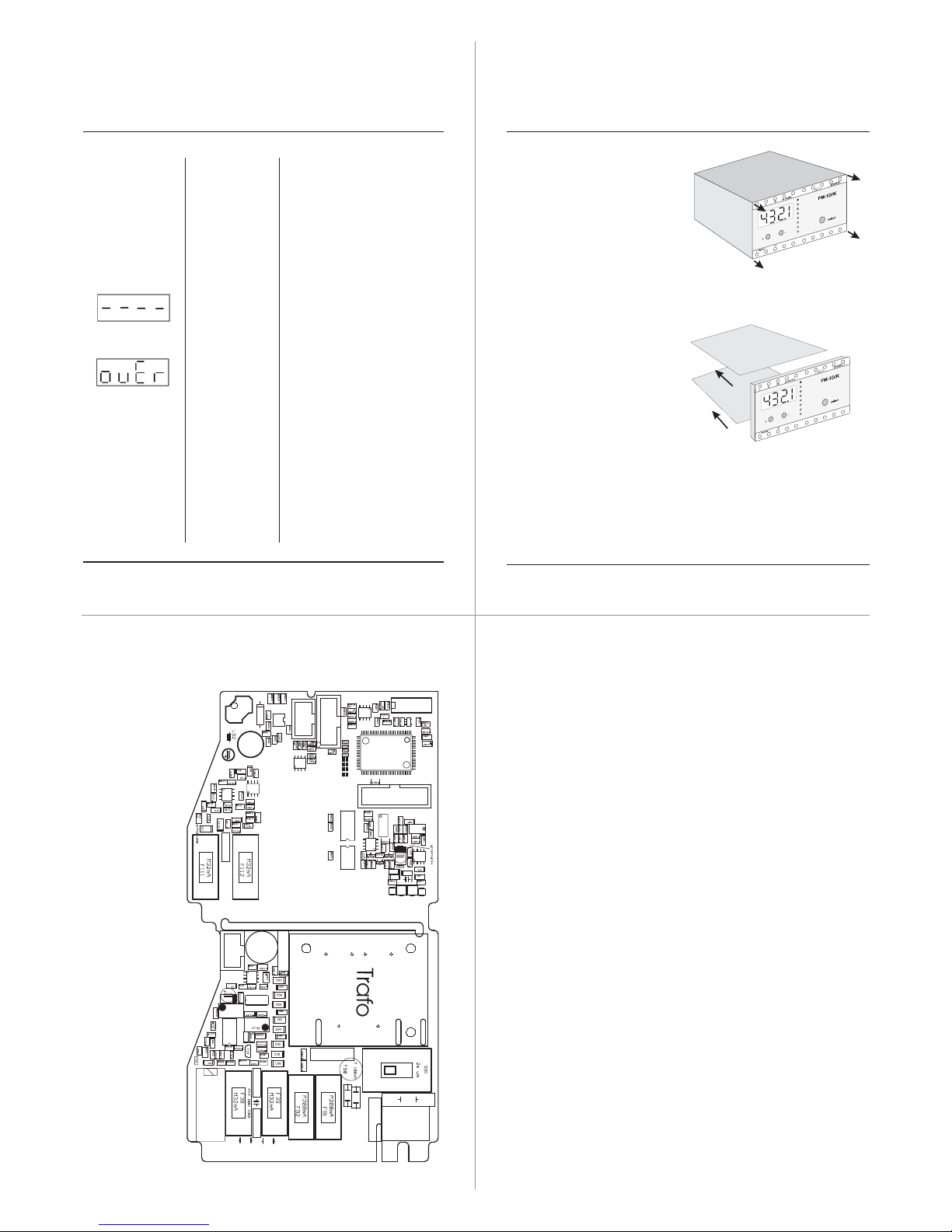
10. Replacing fuses
• Disconnect the power
from the FM-1 D/K
• Remove the 4 screws
from the front plate
• Remove front plate with boards
from the housing
• Remove the board with the blown
fuse from the front plate
• Open the holding device; check
and change the defective fuse
• Assemble the FM-1 D/K
in reverse order
Size of fuses used
F 38 fuse 32 mA medium
F 39 fuse 32 mA medium
F 91 fuse 200 mA medium
F 92 fuse 200 mA medium
F 111fuse 32 mA medium
F 112fuse 32 mA medium
Layout and Fuses
Material number MS5100IN Version: week 12/2008
 Loading...