


DS-W-SR2-00-00-0312-04-A
SR II® Low Lead Meters
Displacement Type Magnetic Drive Cold Water Meters
Description
5/8” (DN 15mm), 3/4” (DN 20mm) and 1” (DN 25mm) Sizes
Measurement of cold water where ow is in one
direction only; in residential, commercial and
industrial services.
Features
CONFORMANCE TO STANDARDS
Sensus SRII Low Lead Water Meters
meet the requirements of NSF Standard
61, Annex F and G and comply with ANSI/
AWWA Standard C700 -latest revision.
Each meter is tested to insure compliance
with AWWA standards.
CONSTRUCTION
Sensus SR II Low Lead Water Meters
consist of three basic components: maincase; measuring chamber; and sealed
register. Maincases are made of Bismuth
BiAlloy CDA89836 or EnviroBrass™ II
C89520 with externally-threaded spuds.
Registers are housed in a bonnet of synthetic polymer. Measuring chambers are
of Rocksyn®, a corrosionresistant, tailored thermoplastic material formulated
for long-term performance and especially
suitable for aggressive water conditions.
Maincase bottom plates are available in
Bismuth BiAlloy, EnviroBrass II or, if frost
protection is desired, in cast iron or synthetic polymer1.
SEALED REGISTER
Hermetically sealed; proven magnetic
drive design eliminates dirt and moisture
contamination, tampering and lens fogging problems. Standard register includes
a straight-reading, odometertype totalization display; a 360° test circle with center
sweep hand; and a low ow (leak) de-
tector. Gears are selubricating, molded
plastic for long life and minimum friction.
No change gears are required for accuracy calibration. Encodertype remote reading systems are available for all SR II Low
Lead Water Meters. (See other side of
sheet for additional information.)
TAMPERPROOF FEATURES
A unique locking system prevents customer removal of the register to obtain
free water. The register can only be removed by breaking the register bonnet.
MAGNETIC DRIVE
The SR II Low Lead features a hydrodynamically cushioned design that eliminates premature wear of components.
The meter utilizes a patented positive,
reliable drive coupling. The highstrength
magnets used will eliminate “drive slip” in
normal use and also provide adequate
strength to drive remote register units.
OPE R ATI O N
Water ows through the meter’s strainer
and into the measuring chamber where it
drives the piston. The hydrodynamically
balanced piston oscillates around a
central hub, guided by the division plate.
A drive magnet transmits the motion of
the piston to a driven magnet located
within the hermetically sealed register.
The driven magnet is connected to the
register gear train. It reduces the piston
oscillations into volume totalization units
displayed on the register dial face.
MAINTENANCE
Sensus SR II Low Lead Water Meters are
engineered to provide long-term value
and virtually maintenance-free operation.
Simplicity of design allows interchangeability of parts of like-size meters, reduced parts inventory requirements, and
ease of maintenance. The register can be
removed without relieving the water pressure or removing the maincase from the
installation.
CONNECTIONS
Tailpieces/Unions for installing the meters
on a variety of pipe types and sizes are
available.
AMR / AMI SYSTEMS
Meters and encoders are compatible with
current Sensus AMR/AMI systems.
GUARANTEE
Sensus SR II Water Meters are backed
by “The Sensus Guarantee.” Ask your
Sensus representative for details or see
Bulletin G-500.
DS-W-SR2-00-00-0312-04-A
A
Page 2 of 3
B
C
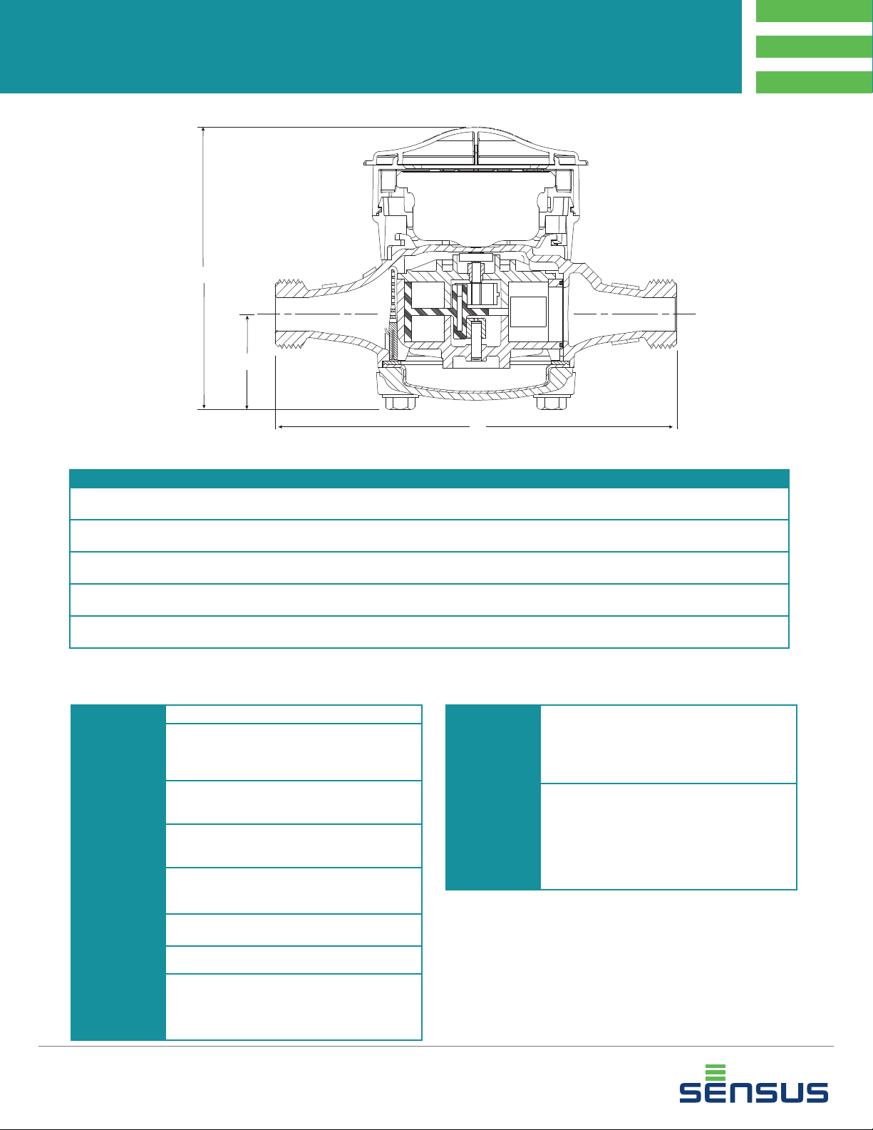
DIMENSIONS AND NET WEIGHTS
Meter Size A B C Width Net Weight
5/8”
(DN 15mm)
5/8” x 3/4”
(DN 15mm X 33mm)
3/4”
(DN 20mm)
3/4” Short
(DN 20mm)
1”
(DN 25mm)
1
With Rocksyn® measuring chamber.
7-1/2 ”
(190m m)
7-1/2 ”
(190m m)
9”
(22 9m m)
7-1/2 ”
(190m m)
10-3/4”
(273mm)
5-3/8”
(136 mm)
5-3/8”
(136 mm)
5- 7/8 ”
(149 mm)
5- 7/8 ”
(149 mm)
7-1/8 ”
(181mm)
1-3/4”
(44 mm)
1-3/4”
(44 mm)
2-3/16 ”
(56 mm)
2-3/16 ”
(56 mm)
2-3/4”
(70 mm)
3-7/8 ”
(98 mm)
3-7/8 ”
(98 mm)
4-1/ 2”
(114 m m)
4-1/ 2”
(114 m m)
6-1/2 ”
(165 mm)
1
4.3 lb.
(1.97 kg)
4.4 lb.
(2.00 kg)
6.4 lb.
(2.90 kg)
6.2 lb.
(2.81 kg)
11. 9 l b.
(5.4 kg)
SPECIFICATIONS
SERVICE Measurement of potable and reclaim water.
NORMAL
OP ER ATIN G
FLOW RANGE
(100%±1.5%)
LOW FLOW
REGISTRATION
(95% - 101.5%)
MAXIMUM
PRESSURE LOSS
MAXIMUM
OP ER ATIN G
PRESSURE
MEASURING
ELEMENT
REGISTER
STANDARD
METER
REGISTRATION
3
5/8” (DN 15mm) size: 1 to 20 gpm (0.25 to 4.5 m3/hr)
3/4” (DN 20mm) size: 2 to 30 gpm (0.45 to 7.0 m3/hr)
1
1” (DN 25mm) size: 3 to 50 gpm (0.7 to 11.0 m3/hr)
5/8” size: 1/4 gpm (0.06 m3/hr)
3/4” size: 1/2 gpm (0.10 m3/hr)
1” size: 3/4 gpm (0.15 m3/hr)
5/8” size: 7.0 psi at 20 gpm (0.5 bar at 4.5 m3/hr)
3/4” size: 9.0 psi at 3 0 gpm (0.6 bar at 7.0 m3/hr)
1” size: 7.3 psi at 50 gpm (0.5 bar at 11.0 m3/hr)
150 psi (10.0 bar)
Oscillating piston
Straight reading, hermetically sealed, magnetic drive.
Remote reading unit optional.
10 gallons, 1 cubic fo ot, or 0.01 m3/ or 0.1 m3/sweep hand
revolution.
10,000,000 gallons, 1,000,000 cubic feet or 100,000 m
3
capacity.
8 odometer wheels
METER
CONNECTIONS
MAT ER IALS Maincase: Bismuth BiAlloy CDA89836 or
1 Maxim um rates listed are for inter mittent ow only. Maximu m conti nuous ow rates
as specied by AW WA are:
5/8” (D N 15mm)—10 gpm (2.3 m3/hr)
3/4” (DN 2 0mm)—15 gpm (3 .4 m3/hr)
1” (DN 25mm) —25 gp m (5.7 m3/hr)
2 Unless other wise no ted, 5/8 ” size and 5/8” x 3/4” chara cteri stics a re ident ical.
5/8” x 3/4” desig nates 5/ 8” with 3/4” con necti on thre ad).
Metri c design ation i s the nor mal bore x the outs ide diam eter.
3
3 See ICE- Opto Register Dat asheet or Elect ronic Re gister D atasheet for det ails
speci cati ons.
5/8” (DN 15mm) size: 3/4” (26.4 4mm) threads
3
5/8” x 3/4” (DN 15mm x 33mm) size: 1” (33. 25mm) threads
3/4” (DN 20mm) size: 1” (33.25mm) threads
1” (DN 25mm ) size: 1-1/4” (41.9mm) threads
(All threads are straight pip e, external type, confor ming to
ANSI B1.20.1 or ISO R2 28, if specied.)
EnviroBrass II C89520
Register box: Synthetic polymer
Measuring chamber: Rocksyn
Bottom plate: Bismuth BiAlloy CDA 89836
Magnets: Plasticized material
Casing bolts: Stainless steel
Strainer: Synthetic polymer
®

DS-W-SR2-00-00-0312-04-A
Page 3 of 3
TYPICAL PERFORMANCE CURVES
SR II Meter
5/8” and 5/8” x 3/4” SR II Meter
UA-5833
1” SR II Meter
UA-5835
3/4” and 3/4” x 1” SR II Meter
UA-5834
3/4” SR II Meter 7-1/2” Laying Length
UA-5838
© All pro ducts purchas ed and servic es perform ed are subject to S ensus’ terms of sal e, available at either; ht tp://na.sensus.com/ TC/TermsCon ditions.pdf or 1-80 0-METE R-IT. Sensus reser ves the right to m odify
these te rms and c ondit ions in it s own discretio n witho ut notic e to the cu stomer.
This doc ument is for informational pur poses o nly, and SEN SUS MA KES NO EXPRESS WA RRANTIES I N THIS D OCUMENT. FURTHER MORE, THERE ARE NO IMPLIED WA RRA NTIES , INCLU DING
WITHO UT LIMITATION, WARR ANTI ES AS TO FITNESS FOR A PARTI CUL AR PURPOSE AND MERCHANTABI LITY. ANY U SE OF TH E PRODU CTS THAT IS NOT S PECIFIC ALLY PERMIT TED HE REIN
IS PROHIBITED.
8601 Six Forks Road, Suite 700
Raleigh, NC 27615
1-800-638-3748
www.sensus.com/water
 Loading...