

Page 1
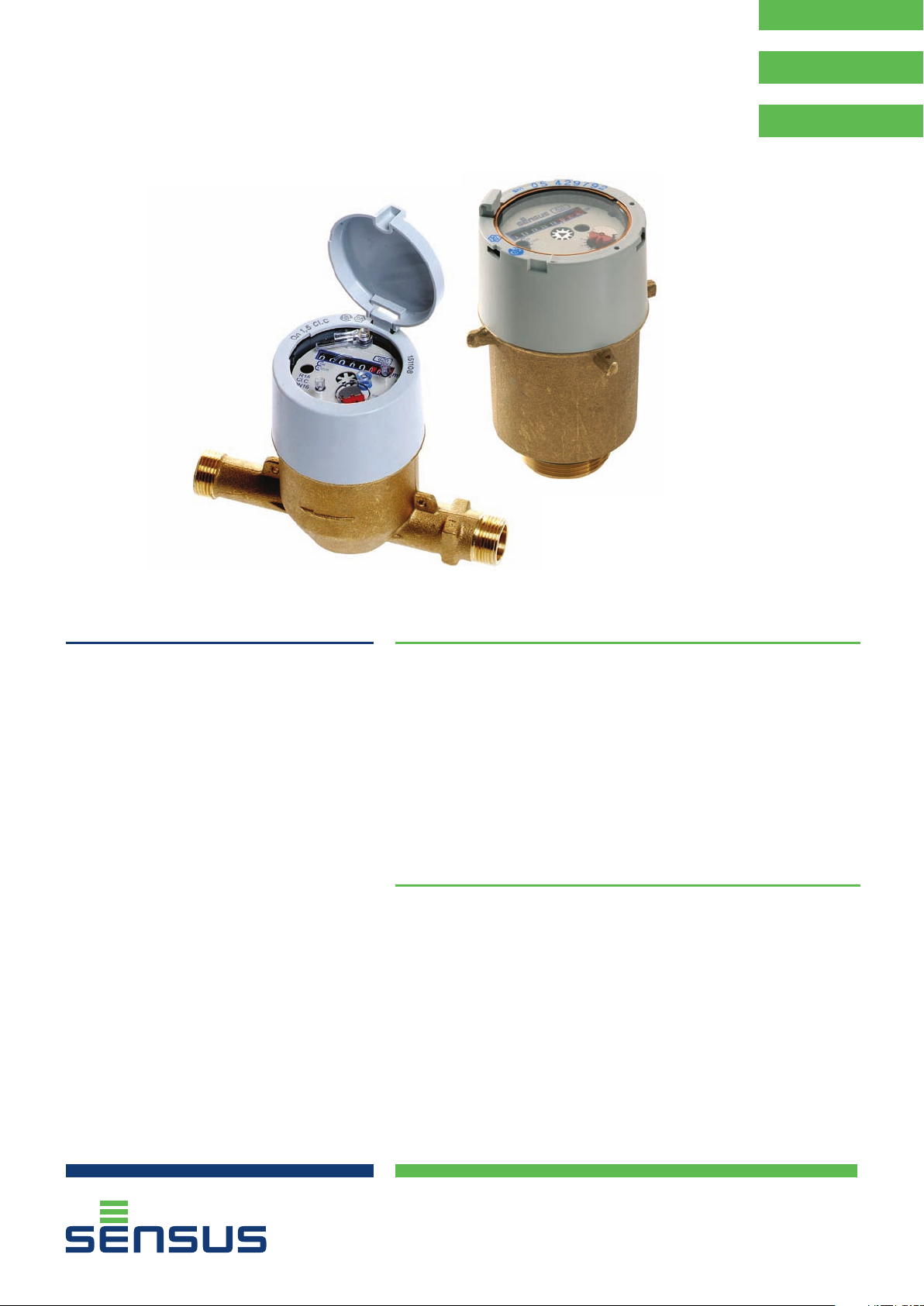
Volumetric Meter
620/620M
Dry Dial
Main characteristics
DN 15 to 40, PN 16
Unrivalled accuracy and measuring range
Small pressure drop
High resistance to impurities
Quiet operation
Available with EEC and MID approvals (DN 15 & 20)
Benefit
The 620 is a high precision meter.
Due to its unique piston measuring chamber even drops of water are counted.
A clear view is either provided through a register with an integrated wiper
or a sealed metal/glass register that does not fog. For a faster and more
comfortable readout the 620 is prepared for AMR.
Due to our broad product range of system solutions you can adapt the 620 to
all your AMR needs.
Not least by its tamper proof design and its long life span you will be glad you
used the 620.
Available options
HRI electronic sensor (Pulse Unit, Data Unit, Radio Sensus((S))cout)
Connectors
Non-return valve
Metal/glass register
www.sensus.com
Page 2
Accuracy
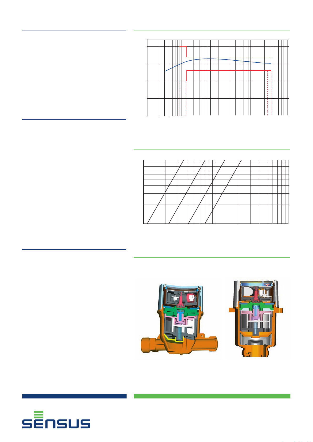
Typical Accuracy Curve
The development of a new material with a density
close to that of water and an enhanced quality of
surface finish results in a piston that glides easily
in the measuring chamber at very low flows. The
smallest leakage downstream of the meter can
therefore be registered.
The measuring range of the 620 meter is much
wider than class C requirements. With the approval
according the new MID regulation a Q3/Q1 ratio up
to 400 can be obtained that combines the precision
at both small and high flowrates.
Reliability
The exclusive composite material of the piston
of the 620 meter combine lightness and excellent
surface conditions. The piston can move in the
measuring chamber without friction and also with
very low wear.
Foreign matter present in water can be filtered
first by the tubular strainer, then by the seat
strainer. The smallest particles can go through the
meter without damage; the elastic pivot enables
the particles to pass between the piston and the
measuring box. In this case, the surface hardness of
the piston and the measuring box avoids scratches.
All the gears are situated in the dry part of the
meter (totalizer), which removes any risk of
blockage due to suspended matter in the water.
The 620 water meter keeps its metrological
accuracy for many years of operation, even in very
difficult working conditions.
5%
0%
-5%
Accuracy(%)
-10%
-15%
Q3/R
Q
Q
1
2
1.6 Q
1
Flow Q
Typical Pressure Drop Curve
1.0
DN 40
Flow (m3/h)
Head loss (bar)
0.1
DN 15
1
DN 20
3 5 7 10 20
DN 25-30
3
Q
4
1.25 Q
3
100
Register
The display of 8 drums (5 for m3, 3 for litres) and
1 pointer ensures perfect readability. The lowest
resolution is 0.05 litres. The dial has a central disc
whose rotation indicates the passage of water. This
indicator can be used to reveal a downstream leak.
The plastic register is equipped with a wiper for
optimum legibility under all conditions. The 620
water meter can operate in any position and its dry
dial can rotate up to 350º. The dial can therefore be
easily read under all conditions of use.
When meters are installed in a very humid
environment (external pit for example) the 620
meter(*) can be supplied with a metal/glass register
giving the guarantee of index readibility.
Cross Section
In-line version
Co-axial version
LD1621INT Page 2
Page 3
Tampering Protection
Performance Data
The 620 meter is designed with tamper protection
to avoid any misuse of the meter.
The plastic register is equipped with a tamper
indicator (blue pin) whose breakage provides
obvious evidence of any tampering attempt with a
screw clamp for example. When using a metal/glass
register, a clear glass break will then occur.
The meter is always equipped as standard with
magnetic protection to protect the magnetic
transmission against magnetic fields.
Any attempt to open the meter bonnet will cause
this plastic part to break.
Approvals
EC pattern approval:
in conformity with
•75/33/EEC
•71/316/EEC
DN 15 & 20 D.96/6.123.05
DN 25 & 30 B.83/32.38
DN 40 B.77/32.04
EC type-examination certificate:
in conformity with
•2004/22/EC(MID)
•EN14154:2007
•OIMLR49:2006
2,5 DE-07-MI001-PTB002
Q
3
4 DE-07-MI001-PTB004
Q
3
Certificate of compliance for potable drinking water
KTW/DVGW (D) Hydrocheck (B)
ACS (F) KIWA (NL)
WRAS (UK)
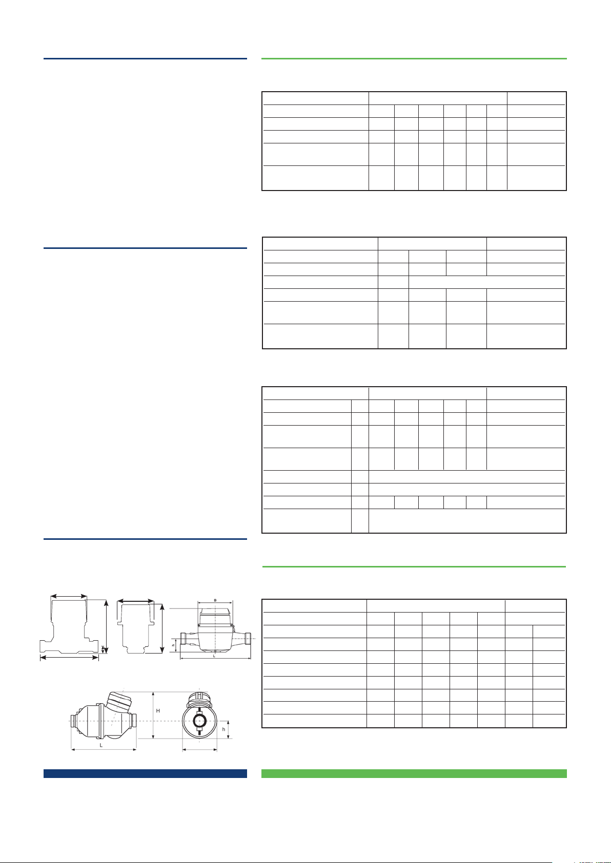
Dimensional Diagram
Metrological Characteristics - EEC Directive 75/33
In-line Co-axial
Nominal Diameter DN mm 15 20 25 30 40 Manifold
Nominal flowrate Q
Maximum flowrate Q
Minimum flowrate
(tolerance ±5%)
Transitional flowrate
(tolerance ±2%)
(1)
Also available with Qn 6
m3/h 1.5 2.5 3.5
n
m3/h 3 5 7 12 20 3
max
Q
l/h 15 25 35 60 100 15
min
Q
l/h 22.5 37.5 52.5 90 150 22.5
t
(1)
6 10 1.5
Metrological Characteristics - Directive
2004/22/EC (MID) & EN 14154
In-line Co-axial
Nominal Size DN mm 15 20 Manifold
Permanent flowrate Q
Ratio “R” Q
Maximum flowrate
Minimum flowrate
(tolerance ±5%)
Transitional flowrate
(tolerance ±2%)
(1)
Values for R = 400
m3/h 2.5 4 2.5
3
R 40 / 80 / 160 / 315 / 400
3/Q1
(1)
Q4 m3/h 3.125 5.0 3.125
Q
l/h 6.3 10.0 6.3
1
(1)
Q2 l/h 10.0 16.0 10.0
Operational Characteristics (manufacturer’s data)
In-line Co-axial
Nominal size DN mm 15 20 25 30 40 Manifold
Starting flowrate
Minimum flowrate
(1)
(±5%)
Transitional flowrate
(±2%)
(1)
Maximum registration m
Lowest resolution l 0.05
Pressure loss at Q
Maximum Working
Pressure PN bar
(1)
typical performance characteristics
(1)
l/h <1 <2 7 7 8 <1
3 6 11 11 20 3
5 12 16 16 30 5
3
10
bar 0.7 0.5 0.28 0.83 0.8 0.7
max
5
16
DN15
D
L
In-line version
Co-axial versions
H
h
Co-axial version
D
DN30-40
Dimensions and Weights
DN20-25
H
Dimensional Characteristics
In-line Co-axial
Nominal size DN mm 15 20 25 30 40 Manifold
(1)
(3)
Length L mm 170
190
(4)
260
260 300 n/a n/a
Width D mm 79.7 93.5 135 135 150 100 93
Total height H mm 132.7 123 186 186 193 135.6 160
Height to pipe axis h mm 15.5 37.5 68 68 75 n/a n/a
(2
Tail inch
)
G3/4”B
G1”B G11/4”B G11/2”B G2”B G11/2”B G11/2”B
piece Diameter mm 26.44 33.25 41.91 47.80 59.61 47.80 47.80
thread Pitch 1.81 2.31 2.31 2.31 2.31 2.31 2.31
Weight kg 1.0 1.6 3.7 3.8 5.0 1.0 1.35
(1) also available in length 110, 114, 115, 130, 134 and165 mm
(2) also available in length 165mm with 1” threads
(3) also available in length 165mm
(4) also available in length 198mm (with Q
4)
3
620 / 620M
LD1621INT Page 3
Page 4
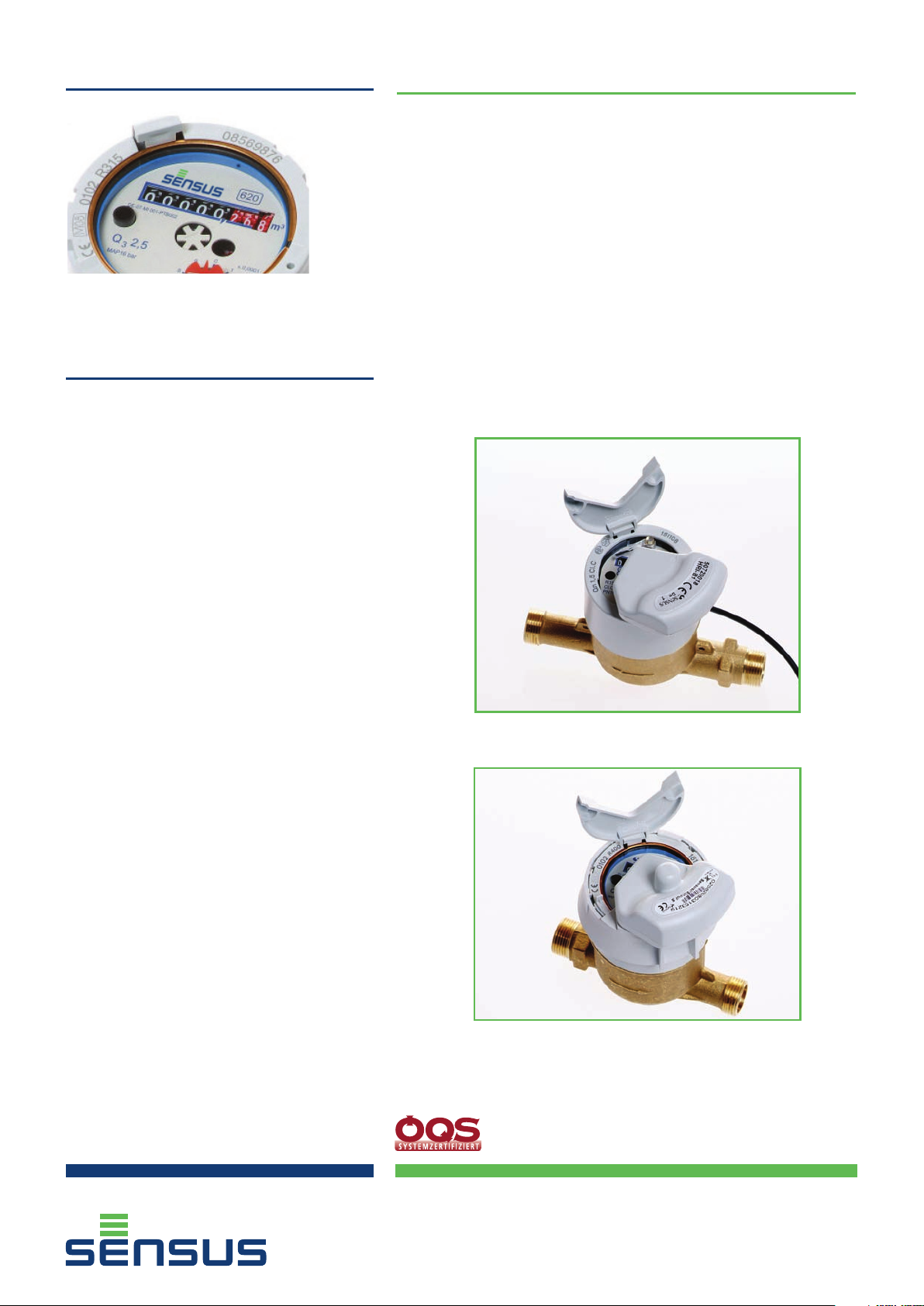
Typical Marking
Marking can vary according different market or
metrological specifications.
AMR fitting
The dial of the 620 meter is equipped as standard
with a pointer able to activate the HRI sensor.
The HRI reproduces the mechanical register index
exactly, by detecting the direction of rotation of
the pointer. It provides a reliable pulse- and data
interface for remote and mobile readout. The
HRI can be fitted in the field on already installed
Sentinel water meters or ordered factory fitted to
the meter.
For more information refer to the leaflets
LS 8100 and LS 3300
The HRI is available as three versions:
Installation and Maintenance Instructions
For complete installation instructions, please refer to MD1001INT manual.
The 620 meter must be installed in a low point of the pipeline, with the arrow
cast on the body showing direction of the water flow. Before fitting the water
meter, all pipework must be flushed out to remove all impurities.
An upstream stop valve is recommended to allow installation and removal of
the water meter.
During tightening, the meter must be maintained in position with a standard
tool using the flat on the meter body.
When turning on the water supply, the upstream valve must be opened
slowly so that the water fills the meter as smoothly as possible.
No special maintenance is required.
1. HRI Pulse Unit (A-version)
The litre pointer activates the HRI allowing a basic
resolution of one litre per pulse. The output pulse
value can be factory set using the divisor D (e.g. D
= 100 means 1 pulse per 100 litres).
The possible pulse output D values are:
1 / 10 / 100 / 1000 / 2.5 / 25 / 250
2. HRI Data Unit (B-version)
The HRI Data Unit is a data interface which supplies
the meter reading as well as the serial or customer
number. This version additionally provides a pulse
output as described above.
The HRI Data Unit can be connected to a M-Bus
network for remote read or a MiniPad for mobile
inductive read (MiniBus), both in accordance with
the IEC 870 protocol.
3. Sensus((S))cout-S Radio Unit
Integrated Sensus((S))cout radio with the usage
of long term proven and reliable HRI sensing
technology. Radio read is made via the handheld
Psion WA pro and Dokom mobile (WinCE) software
Certified according to ISO 9001
Quality Management System ÖQS Reg.no. 3496/0
UK & Ireland Enquiries
Sensus Metering Systems 11 The Quadrangle, Abbey Park, Romsey, Hampshire SO51 9DL UK
T: +44 (0) 1794 526100 F: +44 (0) 1794 526101 Email: [email protected] www.sensus.com
International Enquiries
Sensus GmbH Ludwigshafen Industriestrasse 16, 67063 Ludwigshafen Germany
T: +49 (0) 621-6904-0 F: +49 (0) 621-6904-1409 Email: [email protected] www.sensus.com
09001 Subject to changes without prior notice.
LD1621INT Page 4
 Loading...