

Page 1

®
FlexZone
Fence-mounted Locating Perimeter Intrusion Detection Sensor
Product
Guide
G6DA0102-001 Rev L
November 14, 2018
Page 2

Senstar Corporation
Website: www.senstar.com
Email address: info@senstar.com
G6DA0102-001 Rev L
November 14, 2018
FlexZone, Senstar and the Senstar logo are registered trademarks, and Silver Network is a trademark of Senstar Corporation.
Product names and Company names included in this document are used only for identification purposes and are the property
of, and may be trademarks of, their respective owners. Copyright © 2017, 2014, Senstar Corporation, all rights reserved.
Printed in Canada.
The information provided in this guide has been prepared by Senstar Corporation to the best of its ability. Senstar Corporation is
not responsible for any damage or accidents that may occur due to errors or omissions in this guide. Senstar Corporation is not
liable for any damages, or incidental consequences, arising from the use of, or the inability to use, the software and equipment
described in this guide. Senstar Corporation is not responsible for any damage or accidents that may occur due to information
about items of equipment or components manufactured by other companies. Features and specifications are subject to change
without notice.
Any changes or modifications to the software or equipment that are not expressly approved by Senstar Corporation void the
manufacturer’s warranty, and could void the user’s authority to operate the equipment.
The figures included in this document are for illustration purposes only, and may differ from the actual equipment.
Approvals
Canada: This Class B digital apparatus meets all requirements of the Canadian Interference-Causing Equipment Regulations.
Cet appareil numérique de la classe B respecte toutes les exigences du Règlement sur le matériel brouilleur du Canada.
USA: This device complies with part 15 of the FCC Rules. Operation is subject to the following two conditions: (1) This device
may not cause harmful interference, and (2) this device must accept any interference received, including any interference that
may cause undesired operation.
The use of shielded cables is required for compliance.
Note: This equipment has been tested and found to comply with the limits for a Class B digital device, pursuant to part 15 of the
FCC Rules. These limits are designed to provide reasonable protection against harmful interference in a residential
installation.This equipment generates, uses and can radiate radio frequency energy and, if not installed and used in accordance
with the instructions, may cause harmful interference to radio communications. However, there is no guarantee that interference
will not occur in a particular installation. If this equipment does cause harmful interference to radio or television reception, which
can be determined by turning off and on, the user is encouraged to try to correct the interference by one or more of the following
measures:
- Reorient or relocate the receiving antenna.
- Increase the separation distance between the equipment and the receiver.
- Connect the equipment into an outlet on a circuit different from that to which the receiver is connected.
- Consult the dealer or an experienced radio/TV technician for help.
Europe: This device conforms to the protection requirement of council directives 89/336/EEC on the approximation of the laws
of member states relating to Electromagnetic compatibility, amended by directive 93/68/EEC.
The use of shielded cables is required for compliance.
Senstar Corporation’s Quality Management System is ISO 9001:2008 registered.
Page 2 FlexZone Product Guide
Page 3

Table of Contents
1 System planning - - - - - - - - - - - - - - - - - - - - - - - - - - - - - - - - - - - - - - - - - -7
Introduction - - - - - - - - - - - - - - - - - - - - - - - - - - - - - - - - - - - - - - - - - - - - - - - - - - - 7
Installation overview - - - - - - - - - - - - - - - - - - - - - - - - - - - - - - - - - - - - - - - - - - - - - - - - 7
Security factors - - - - - - - - - - - - - - - - - - - - - - - - - - - - - - - - - - - - - - - - - - - - - - - - - 8
Fence structures - - - - - - - - - - - - - - - - - - - - - - - - - - - - - - - - - - - - - - - - - - - - - - - - 8
Standard flexible fence types - - - - - - - - - - - - - - - - - - - - - - - - - - - - - - - - - - - - - - - - - - 9
Chain-link fence - - - - - - - - - - - - - - - - - - - - - - - - - - - - - - - - - - - - - - - - - - - - - - - - - - - - - - -9
Welded-mesh fences - - - - - - - - - - - - - - - - - - - - - - - - - - - - - - - - - - - - - - - - - - - - - - - - - - - - 9
Expanded metal fences - - - - - - - - - - - - - - - - - - - - - - - - - - - - - - - - - - - - - - - - - - - - - - - - - - 9
Rigid fence types - - - - - - - - - - - - - - - - - - - - - - - - - - - - - - - - - - - - - - - - - - - - - - - - - 10
Palisade fences - - - - - - - - - - - - - - - - - - - - - - - - - - - - - - - - - - - - - - - - - - - - - - - - - - - - - - 10
Climb-over deterrent hardware - - - - - - - - - - - - - - - - - - - - - - - - - - - - - - - - - - - - - - - 10
Barbed wire - - - - - - - - - - - - - - - - - - - - - - - - - - - - - - - - - - - - - - - - - - - - - - - - - - - - - - - - - 10
Razor ribbon - - - - - - - - - - - - - - - - - - - - - - - - - - - - - - - - - - - - - - - - - - - - - - - - - - - - - - - - - 10
Gates - - - - - - - - - - - - - - - - - - - - - - - - - - - - - - - - - - - - - - - - - - - - - - - - - - - - - - - - - 11
Buildings, walls and other structures - - - - - - - - - - - - - - - - - - - - - - - - - - - - - - - - - 12
Environment - - - - - - - - - - - - - - - - - - - - - - - - - - - - - - - - - - - - - - - - - - - - - - - - - - 12
Site Survey - - - - - - - - - - - - - - - - - - - - - - - - - - - - - - - - - - - - - - - - - - - - - - - - - - - 13
Perimeter layout guidelines - - - - - - - - - - - - - - - - - - - - - - - - - - - - - - - - - - - - - - - 14
FlexZone sensor cable - - - - - - - - - - - - - - - - - - - - - - - - - - - - - - - - - - - - - - - - - - - - - 14
Cable layout guidelines - - - - - - - - - - - - - - - - - - - - - - - - - - - - - - - - - - - - - - - - - - - - - 15
Cable length calculator (flexible fences) - - - - - - - - - - - - - - - - - - - - - - - - - - - - - - - - - - - - - 15
Rigid fences - - - - - - - - - - - - - - - - - - - - - - - - - - - - - - - - - - - - - - - - - - - - - - - - - - - - - - - - - 16
Fence height recommendations - - - - - - - - - - - - - - - - - - - - - - - - - - - - - - - - - - - - - - - - - - - 16
Non-detecting cable - - - - - - - - - - - - - - - - - - - - - - - - - - - - - - - - - - - - - - - - - - - - - - - - - - - 16
Fence corners and heavier gauge posts (flexible fences) - - - - - - - - - - - - - - - - - - - - - - - - - 17
Zone demarcation loops (flexible fences) - - - - - - - - - - - - - - - - - - - - - - - - - - - - - - - - - - - - - 17
Service loops (flexible fences) - - - - - - - - - - - - - - - - - - - - - - - - - - - - - - - - - - - - - - - - - - - - 17
Drip loops (flexible fences) - - - - - - - - - - - - - - - - - - - - - - - - - - - - - - - - - - - - - - - - - - - - - - - 17
Termination loops (flexible fences) - - - - - - - - - - - - - - - - - - - - - - - - - - - - - - - - - - - - - - - - - 17
Splice loops (flexible fences) - - - - - - - - - - - - - - - - - - - - - - - - - - - - - - - - - - - - - - - - - - - - - 17
Gate bypass - - - - - - - - - - - - - - - - - - - - - - - - - - - - - - - - - - - - - - - - - - - - - - - - - - - - - - - - - 18
Armored cable - - - - - - - - - - - - - - - - - - - - - - - - - - - - - - - - - - - - - - - - - - - - - - - - - - - - - - - 18
Double pass coverage - - - - - - - - - - - - - - - - - - - - - - - - - - - - - - - - - - - - - - - - - - - - - 18
Processor location guidelines - - - - - - - - - - - - - - - - - - - - - - - - - - - - - - - - - - - - - - - - 19
Power source and wiring - - - - - - - - - - - - - - - - - - - - - - - - - - - - - - - - - - - - - - - - - - - - 20
Power over the sensor cables - - - - - - - - - - - - - - - - - - - - - - - - - - - - - - - - - - - - - - - - - - - - 20
FlexZone Product Guide Page 3
Page 4

Auxiliary device output power - - - - - - - - - - - - - - - - - - - - - - - - - - - - - - - - - - - - - - - - - - - - 20
Power over Ethernet - - - - - - - - - - - - - - - - - - - - - - - - - - - - - - - - - - - - - - - - - - - - - - - - - - - 21
Grounding considerations - - - - - - - - - - - - - - - - - - - - - - - - - - - - - - - - - - - - - - - - - - - - - - - 21
Alarm communication options - - - - - - - - - - - - - - - - - - - - - - - - - - - - - - - - - - - - - - - - -22
Fail-safe relay operation - - - - - - - - - - - - - - - - - - - - - - - - - - - - - - - - - - - - - - - - - - - - - - - - 22
Relay Output Card - - - - - - - - - - - - - - - - - - - - - - - - - - - - - - - - - - - - - - - - - - - - - - - - - - - - 22
Dry Contact Input Card - - - - - - - - - - - - - - - - - - - - - - - - - - - - - - - - - - - - - - - - - - - - - - - - - 22
Data over the sensor cables - - - - - - - - - - - - - - - - - - - - - - - - - - - - - - - - - - - - - - - - - -22
Processor synchronization - - - - - - - - - - - - - - - - - - - - - - - - - - - - - - - - - - - - - - - - - - -23
Alarm monitoring - - - - - - - - - - - - - - - - - - - - - - - - - - - - - - - - - - - - - - - - - - - - - - - - - -23
NM Mode - - - - - - - - - - - - - - - - - - - - - - - - - - - - - - - - - - - - - - - - - - - - - - - - - - - - - - - - - - 23
Cable connectors - - - - - - - - - - - - - - - - - - - - - - - - - - - - - - - - - - - - - - - - - - - - - - - - - -23
High security installations - - - - - - - - - - - - - - - - - - - - - - - - - - - - - - - - - - - - - - - - -24
High-security installation rules - - - - - - - - - - - - - - - - - - - - - - - - - - - - - - - - - - - - - - - - - - - - 24
2 Installation - - - - - - - - - - - - - - - - - - - - - - - - - - - - - - - - - - - - - - - - - - - - - 25
Installing the sensor cable - - - - - - - - - - - - - - - - - - - - - - - - - - - - - - - - - - - - - - - -25
Cable handling rules - - - - - - - - - - - - - - - - - - - - - - - - - - - - - - - - - - - - - - - - - - - - - - - -25
FlexZone sensor cable conditioning - - - - - - - - - - - - - - - - - - - - - - - - - - - - - - - - - - - - -26
Cable conditioning procedure (part 1 - cable preparation) - - - - - - - - - - - - - - - - - - - - - - - - 26
Cable conditioning procedure (part 2 - cable flossing) - - - - - - - - - - - - - - - - - - - - - - - - - - - 27
Installing cable on chain-link fences - - - - - - - - - - - - - - - - - - - - - - - - - - - - - - - - - - - - -29
Installing cable ties - - - - - - - - - - - - - - - - - - - - - - - - - - - - - - - - - - - - - - - - - - - - - - - - - - - - 29
Bend radius - - - - - - - - - - - - - - - - - - - - - - - - - - - - - - - - - - - - - - - - - - - - - - - - - - - - - - - - - 30
At fence posts - - - - - - - - - - - - - - - - - - - - - - - - - - - - - - - - - - - - - - - - - - - - - - - - - - - - - - - 30
At corners or heavy gauge posts - - - - - - - - - - - - - - - - - - - - - - - - - - - - - - - - - - - - - - - - - - 30
At software defined zone boundaries - - - - - - - - - - - - - - - - - - - - - - - - - - - - - - - - - - - - - - - 31
Service loops - - - - - - - - - - - - - - - - - - - - - - - - - - - - - - - - - - - - - - - - - - - - - - - - - - - - - - - - 31
Drip loops - - - - - - - - - - - - - - - - - - - - - - - - - - - - - - - - - - - - - - - - - - - - - - - - - - - - - - - - - - 32
Termination loops - - - - - - - - - - - - - - - - - - - - - - - - - - - - - - - - - - - - - - - - - - - - - - - - - - - - - 32
Splice loops - - - - - - - - - - - - - - - - - - - - - - - - - - - - - - - - - - - - - - - - - - - - - - - - - - - - - - - - - 33
Installing cable on welded-mesh fence - - - - - - - - - - - - - - - - - - - - - - - - - - - - - - - - - - -34
Double pass cable installation - - - - - - - - - - - - - - - - - - - - - - - - - - - - - - - - - - - - - - - - -35
Installing cable on rigid fences - - - - - - - - - - - - - - - - - - - - - - - - - - - - - - - - - - - - - - - - -36
Sensor cable connections - - - - - - - - - - - - - - - - - - - - - - - - - - - - - - - - - - - - - - - - - - - -36
Cable preparation (all connections) - - - - - - - - - - - - - - - - - - - - - - - - - - - - - - - - - - - - - - - - 37
Processor connections - - - - - - - - - - - - - - - - - - - - - - - - - - - - - - - - - - - - - - - - - - - - - - - - - 38
Sensor cable splices - - - - - - - - - - - - - - - - - - - - - - - - - - - - - - - - - - - - - - - - - - - - - - - - - - - 39
Sensor cable terminations - - - - - - - - - - - - - - - - - - - - - - - - - - - - - - - - - - - - - - - - - - - - - - - 40
Using the Wireless Gate Sensor to protect gates - - - - - - - - - - - - - - - - - - - - - - - - - - -42
Installing sensor cable on gates - - - - - - - - - - - - - - - - - - - - - - - - - - - - - - - - - - - - - - - -42
Gate bypass cable - - - - - - - - - - - - - - - - - - - - - - - - - - - - - - - - - - - - - - - - - - - - - - - - - - - - 43
Bypass cable installation instructions - - - - - - - - - - - - - - - - - - - - - - - - - - - - - - - - - - - - - - - 43
Installing sensor cable on swinging gates - - - - - - - - - - - - - - - - - - - - - - - - - - - - - - - - - - - - 43
Gate disconnect assembly - - - - - - - - - - - - - - - - - - - - - - - - - - - - - - - - - - - - - - - - - - -44
Installation instructions - - - - - - - - - - - - - - - - - - - - - - - - - - - - - - - - - - - - - - - - - - - - - - - - - 44
Installing armored FlexZone sensor cable - - - - - - - - - - - - - - - - - - - - - - - - - - - - - - - -45
Installing armored FlexZone sensor cable - - - - - - - - - - - - - - - - - - - - - - - - - - - - - - - - - - - - 46
Installing cable on barbed wire - - - - - - - - - - - - - - - - - - - - - - - - - - - - - - - - - - - - - - - -46
On razor ribbon - - - - - - - - - - - - - - - - - - - - - - - - - - - - - - - - - - - - - - - - - - - - - - - - - - - - - - 46
Splicing armored sensor cable - - - - - - - - - - - - - - - - - - - - - - - - - - - - - - - - - - - - - - - - - - - - 46
Armored cable terminations - - - - - - - - - - - - - - - - - - - - - - - - - - - - - - - - - - - - - - - - - - - - - - 48
Connecting armored sensor cable to the processor - - - - - - - - - - - - - - - - - - - - - - - - - -50
Page 4 FlexZone Product Guide
Page 5

Installing the FlexZone processor - - - - - - - - - - - - - - - - - - - - - - - - - - - - - - - - - - - 51
Cable entry ports - - - - - - - - - - - - - - - - - - - - - - - - - - - - - - - - - - - - - - - - - - - - - - - - - - - - - - 52
Free-standing or fence post mounting the enclosure - - - - - - - - - - - - - - - - - - - - - - - - - - - - - 53
Surface mounting - - - - - - - - - - - - - - - - - - - - - - - - - - - - - - - - - - - - - - - - - - - - - - - - - - - - - 54
Grounding - - - - - - - - - - - - - - - - - - - - - - - - - - - - - - - - - - - - - - - - - - - - - - - - - - - - - - 55
Relay outputs - - - - - - - - - - - - - - - - - - - - - - - - - - - - - - - - - - - - - - - - - - - - - - - - - - - - 55
Relay contact ratings - - - - - - - - - - - - - - - - - - - - - - - - - - - - - - - - - - - - - - - - - - - - - - - - - - - 55
Auxiliary inputs /Self-test inputs - - - - - - - - - - - - - - - - - - - - - - - - - - - - - - - - - - - - - - - 55
Processor wiring connections - - - - - - - - - - - - - - - - - - - - - - - - - - - - - - - - - - - - - - - - 56
Silver Network wiring connections - - - - - - - - - - - - - - - - - - - - - - - - - - - - - - - - - - - - - 58
Silver Network specifications - - - - - - - - - - - - - - - - - - - - - - - - - - - - - - - - - - - - - - - - - - - - - 58
Silver Network data path connections - - - - - - - - - - - - - - - - - - - - - - - - - - - - - - - - - - - 60
Power connections - - - - - - - - - - - - - - - - - - - - - - - - - - - - - - - - - - - - - - - - - - - - - - - - 63
Power over sensor cables - - - - - - - - - - - - - - - - - - - - - - - - - - - - - - - - - - - - - - - - - - - - - - - 63
Local power supply - - - - - - - - - - - - - - - - - - - - - - - - - - - - - - - - - - - - - - - - - - - - - - - - - - - - 63
Power over Ethernet - - - - - - - - - - - - - - - - - - - - - - - - - - - - - - - - - - - - - - - - - - - - - - - - - - - 64
Auxiliary device power output - - - - - - - - - - - - - - - - - - - - - - - - - - - - - - - - - - - - - - - - - - - - - 64
Backup power - - - - - - - - - - - - - - - - - - - - - - - - - - - - - - - - - - - - - - - - - - - - - - - - - - - - - - - - 64
3 Calibration & setup - - - - - - - - - - - - - - - - - - - - - - - - - - - - - - - - - - - - - - - 67
The Universal Configuration Module - - - - - - - - - - - - - - - - - - - - - - - - - - - - - - - - - - - 67
FlexZone definitions - - - - - - - - - - - - - - - - - - - - - - - - - - - - - - - - - - - - - - - - - - - - - - - - - - - 68
Understanding FlexZone alarm detection - - - - - - - - - - - - - - - - - - - - - - - - - - - - - - - - 68
Intruder detection - - - - - - - - - - - - - - - - - - - - - - - - - - - - - - - - - - - - - - - - - - - - - - - - - 69
Intrusion detection - - - - - - - - - - - - - - - - - - - - - - - - - - - - - - - - - - - - - - - - - - - - - - - - - - - - - 69
Initial processor setup - - - - - - - - - - - - - - - - - - - - - - - - - - - - - - - - - - - - - - - - - - - 70
Connecting the UCM via USB - - - - - - - - - - - - - - - - - - - - - - - - - - - - - - - - - - - - - - - - 70
Setting the processor address - - - - - - - - - - - - - - - - - - - - - - - - - - - - - - - - - - - - - - - - 70
Network configuration - - - - - - - - - - - - - - - - - - - - - - - - - - - - - - - - - - - - - - - - - - - - - - 70
Sensor cable supervision - - - - - - - - - - - - - - - - - - - - - - - - - - - - - - - - - - - - - - - - - - - 71
Adjacent Processor (m) setting - - - - - - - - - - - - - - - - - - - - - - - - - - - - - - - - - - - - - - - - - - - - 71
Power over sensor cables - - - - - - - - - - - - - - - - - - - - - - - - - - - - - - - - - - - - - - - - - - - 72
Processor synchronization - - - - - - - - - - - - - - - - - - - - - - - - - - - - - - - - - - - - - - - - - - 73
Audio “listen-in” function - - - - - - - - - - - - - - - - - - - - - - - - - - - - - - - - - - - - - - - - - - - - 73
Using the Audio listen-in function via the UCM - - - - - - - - - - - - - - - - - - - - - - - - - - - - - - - - - 73
Using the Audio listen-in function via the FlexZone Audio Tool - - - - - - - - - - - - - - - - - - - - - 74
Processor calibration - - - - - - - - - - - - - - - - - - - - - - - - - - - - - - - - - - - - - - - - - - - - 75
The Sensitivity Profile - - - - - - - - - - - - - - - - - - - - - - - - - - - - - - - - - - - - - - - - - - - - - - 75
Recording the Sensitivity Profile - - - - - - - - - - - - - - - - - - - - - - - - - - - - - - - - - - - - - - - - - - - 75
Detection parameter setup - - - - - - - - - - - - - - - - - - - - - - - - - - - - - - - - - - - - - - - - - - 77
Defining a zone - - - - - - - - - - - - - - - - - - - - - - - - - - - - - - - - - - - - - - - - - - - - - - - - - - - - - - - 77
Setting the cable Threshold - - - - - - - - - - - - - - - - - - - - - - - - - - - - - - - - - - - - - - - - - - - - - - 77
Defining the cable segments and alarm zones - - - - - - - - - - - - - - - - - - - - - - - - - - - - 78
Locating the cable segment boundaries - - - - - - - - - - - - - - - - - - - - - - - - - - - - - - - - - - - - - 78
Defining the cable segment boundaries - - - - - - - - - - - - - - - - - - - - - - - - - - - - - - - - - - - - - - 78
Defining sensor cable as non-detecting (setting the start point of detecting cable) - - - - - - - - 79
Defining the detecting cable segments - - - - - - - - - - - - - - - - - - - - - - - - - - - - - - - - - - - - - - 79
Setting the endpoint of detecting cable - - - - - - - - - - - - - - - - - - - - - - - - - - - - - - - - - - - - - - 80
Setting individual cable segment thresholds - - - - - - - - - - - - - - - - - - - - - - - - - - - - - - 81
Setting the segment threshold - - - - - - - - - - - - - - - - - - - - - - - - - - - - - - - - - - - - - - - - - - - - 81
Intrusion simulations - - - - - - - - - - - - - - - - - - - - - - - - - - - - - - - - - - - - - - - - - - - - - - - 81
FlexZone Product Guide Page 5
Page 6

Input/output configuration - - - - - - - - - - - - - - - - - - - - - - - - - - - - - - - - - - - - - - - - -82
Specify the Auxiliary I/O control mode and option card - - - - - - - - - - - - - - - - - - - - - - -82
Auxiliary (Aux) inputs - - - - - - - - - - - - - - - - - - - - - - - - - - - - - - - - - - - - - - - - - - - - - - -82
Local control mode - - - - - - - - - - - - - - - - - - - - - - - - - - - - - - - - - - - - - - - - - - - - - - - - - - - - 83
Remote control mode - - - - - - - - - - - - - - - - - - - - - - - - - - - - - - - - - - - - - - - - - - - - - - - - - - 83
Input configuration procedure (Remote control mode) - - - - - - - - - - - - - - - - - - - - - - - - - - - 84
Output relays - - - - - - - - - - - - - - - - - - - - - - - - - - - - - - - - - - - - - - - - - - - - - - - - - - - - -84
Output relay setup (Local control mode) - - - - - - - - - - - - - - - - - - - - - - - - - - - - - - - - - - - - - 84
Output relay setup (Remote control mode) - - - - - - - - - - - - - - - - - - - - - - - - - - - - - - - - - - - 84
Linking cable segments to relays (local control mode) - - - - - - - - - - - - - - - - - - - - - - - -85
System test procedure - - - - - - - - - - - - - - - - - - - - - - - - - - - - - - - - - - - - - - - - - - -85
4 Maintenance - - - - - - - - - - - - - - - - - - - - - - - - - - - - - - - - - - - - - - - - - - - - 87
Recommended maintenance - - - - - - - - - - - - - - - - - - - - - - - - - - - - - - - - - - - - - -87
Preventing weather related nuisance alarms - - - - - - - - - - - - - - - - - - - - - - - - - - - - - - - - - - 88
Using the SD card function - - - - - - - - - - - - - - - - - - - - - - - - - - - - - - - - - - - - - - - - - - - - - - 88
Testing the fence condition - - - - - - - - - - - - - - - - - - - - - - - - - - - - - - - - - - - - - - - - - - - - - - 88
Ground faults - - - - - - - - - - - - - - - - - - - - - - - - - - - - - - - - - - - - - - - - - - - - - - - - - - - - - - - - 88
Adjusting the Target Filters - - - - - - - - - - - - - - - - - - - - - - - - - - - - - - - - - - - - - - - - - - - - - - 89
Replacing the processor - - - - - - - - - - - - - - - - - - - - - - - - - - - - - - - - - - - - - - - - - -90
Removing the processor assembly - - - - - - - - - - - - - - - - - - - - - - - - - - - - - - - - - - - - - - - - 90
Replacing the processor assembly - - - - - - - - - - - - - - - - - - - - - - - - - - - - - - - - - - - - - - - - - 90
Updating the firmware - - - - - - - - - - - - - - - - - - - - - - - - - - - - - - - - - - - - - - - - - - -91
a Parts list - - - - - - - - - - - - - - - - - - - - - - - - - - - - - - - - - - - - - - - - - - - - - - - 93
b Specifications - - - - - - - - - - - - - - - - - - - - - - - - - - - - - - - - - - - - - - - - - - - 97
c NM Mode - - - - - - - - - - - - - - - - - - - - - - - - - - - - - - - - - - - - - - - - - - - - - - - 99
UCM configuration - - - - - - - - - - - - - - - - - - - - - - - - - - - - - - - - - - - - - - - - - - - - - - - -100
Page 6 FlexZone Product Guide
Page 7

1 System planning
Introduction
The FlexZone fence protection system uses loose-tube coaxial sensor cables mounted on a fence
to detect vibrations caused by climbing, cutting, lifting, or otherwise disturbing the fence fabric.
Each FlexZone processor can monitor the activity from one or two sensor cables, each up to
300 m (984 ft.) long, and will report the alarm status of up to 60 software defined sensor zones.
FlexZone will locate the source of a disturbance to within ± 3 m (10 ft.). A single pass of sensor
cable can protect a high quality chain-link fence with no middle rail, up to 4.3 m (14 ft.) high.
Additional passes of sensor cable are recommended for chain-link fences that are higher than
4.3 m.
There are two models of the FlexZone processor available. Both models process alarm data the
same way. However, the FlexZone-4 processor supports up to 4 software defined alarm zones, but
does not report target location. The FlexZone-60 processor supports up to 60 distinct alarm zones
and reports target location.
This Product Guide covers FlexZone installation and setup for chainlink, welded-mesh, expanded
metal and palisade fences.
Installation overview
Installing a FlexZone system is a four step process:
1. Plan and design the system.
2. Inspect and if necessary, repair the fence and the surrounding area.
3. Install the sensor cable, processor and enclosure.
• ground rod (if required)
• alarm communication wiring
• power supply
4. Setup and calibrate the system.
FlexZone Product Guide Page 7
Page 8

Security factors
Security factors
There are many important factors to consider when planning a fence-mounted perimeter security
system:
• Fence height - The fence must be high enough to present an effective barrier to climb-over
intrusions. It should also include climb-over deterrent hardware such as barbed wire or razor
ribbon (for flexible fences). Rigid fence types should incorporate a climb over deterrent in their
design (pointed stakes or pales). Senstar recommends that the minimum fence height for a
FlexZone installation on a flexible fence type is 2.5 m (8 ft.). For rigid fence types the minimum
recommended fence height is 2 m (6.5 ft.).
• Fence condition - FlexZone detects intrusions by picking up the minute vibrations or fence
noise caused by an intrusion attempt. Therefore, the fence must be in good condition to
prevent any metal on metal contact or vibrations caused by environmental factors. It may be
necessary to upgrade the perimeter fences to ensure they present sufficient barriers against
climb over and crawl under intrusions. If you are not sure of the suitability of your fence for a
FlexZone sensor, Senstar recommends hiring a local fencing contractor to inspect, and if
required, repair the fence.
• Probability of detection (Pd) vs. nuisance alarm rate (NAR) - With a fence-mounted intrusion
detection system there is always a trade-off between the probability of detection and the
nuisance alarm rate. A properly calibrated system will provide a high Pd and will minimize the
NAR.
• Alarm assessment/response - What happens when the system triggers an alarm? Can the
alarm be assessed visually? Does the site include CCTV coverage to verify the event?
Senstar recommends engaging a security consultant to discuss the available methods of
alarm assessment. To ensure maximum confidence in the sensor you must be able to
distinguish between valid alarms and nuisance alarms.
Fence structures
To ensure consistent detection, a sensor cable should be mounted on only one type of fence. All of
the fence panels should be similar in type, size and condition. Ensure that there are no loose
panels, fittings or metal parts that can move and cause nuisance alarms. A shake test in which you
grip the fence fabric in the middle of a panel and gently shake it back and forth with an increasing
motion will help identify any loose pieces. Listen for metal-on-metal contact and correct any
problems found. Verify that there are no washouts or depressions under the fence that could allow
an intruder access. Ensure that there is no vegetation or other objects that can make contact with
the fence in windy conditions.
Note Fences that are covered with vinyl privacy slats or other screening
material may not be suitable for the FlexZone sensor due to the
vibration dampening characteristics of the screening materials, and the
additional fence motion caused by wind. It may be necessary to remove
the screening material to ensure optimal FlexZone sensor performance.
Page 8 FlexZone Product Guide
Page 9
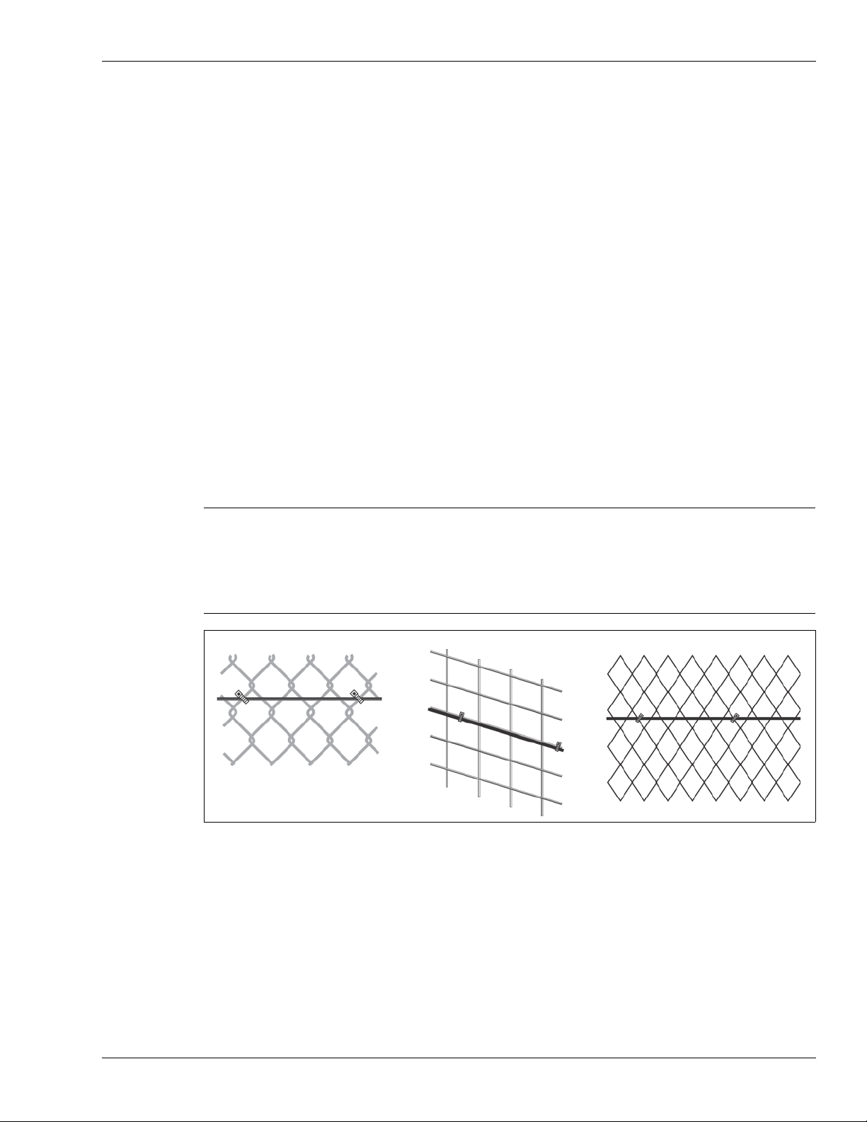
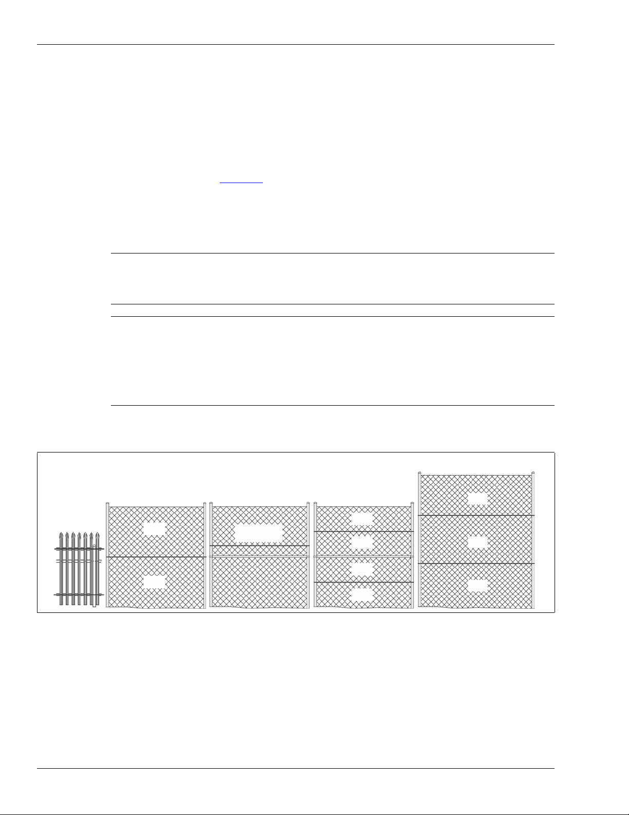
Standard flexible fence types
chain-link welded-mesh
expanded metal
Chain-link fence
Chain-link fence is comprised of steel wires that are bent lengthwise into zig-zag patterns. The
zig-zag wires are vertically woven to form the characteristic diamond pattern. The fence fabric is
attached to fence posts approximately 3 m (10 ft.) apart. Tension wires are often used to stiffen the
fence fabric at the top, bottom and middle of the fence. Chain-link fences are available in different
heights and are sometimes vinyl coated.
Welded-mesh fences
A typical welded-mesh fence section consists of steel wire welded into a grid, with horizontal
spacing differing from vertical spacing. These fence sections are secured to fence posts and often
include top and bottom rails.
Expanded metal fences
Expanded metal mesh is typically comprised of a metal material with diamond shaped holes.
Metals can be expanded in a range of material thickness and to a broad choice of patterns to suit
specific applications. Expanded metal mesh is available with a variety of diamond size openings
and gauges that can be attached to a typical fence framework of round pipe and line rails.
Fence structures
Note High-security welded-mesh and expanded metal fences are comprised
of heavier gauge metal than the standard flexible fence types.
Therefore, these high-security fence types may have to be defined as
Rigid fences via the UCM. Begin testing with the Flexible fence setting
and use the Rigid fence setting only if adequate detection sensitivity
cannot be achieved at the Flexible fence setting.
Figure 1: Standard flexible fence types
FlexZone Product Guide Page 9
Page 10
Fence structures
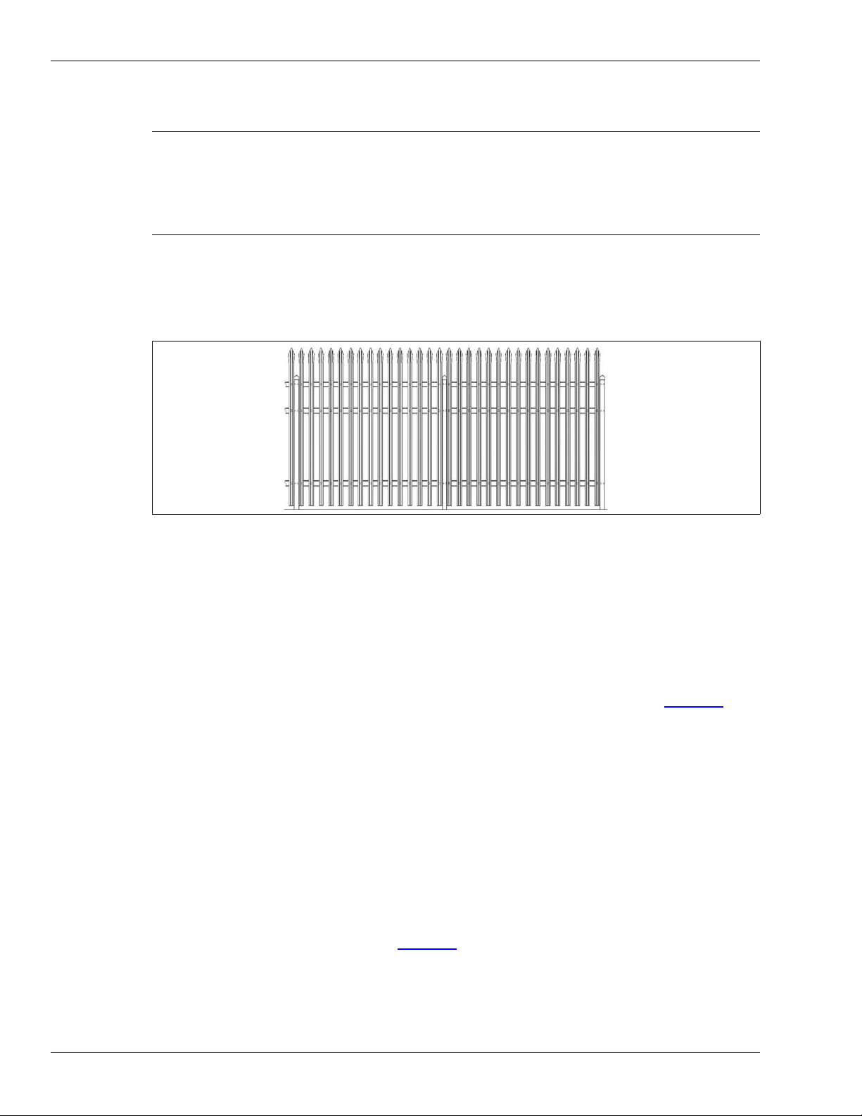
Rigid fence types
Note Rigid fence types do not conduct vibrations as well as flexible fence
types due to their materials and construction. FlexZone provides an
increased sensitivity setting for use with rigid fences. Senstar
recommends installing the FlexZone sensor on a limited length section
of the rigid fence to test and verify that the detection sensitivity meets
the security requirements before installing a full length perimeter.
Palisade fences
A typical palisade fence panel consists of metal pales fastened onto horizontal rails. These fence
sections are secured to fence posts which are securely anchored to, or into, the ground.
Figure 2: Rigid fence (palisade)
Climb-over deterrent hardware
Barbed wire
Senstar recommends using armored sensor cable on barbed wire. Armored cable is comprised of
FlexZone sensor cable inside flexible metal conduit. To protect both the fence and the barbed
wire, use armored cable on the barbed wire, and use sensor cable on the fence fabric. Install
armored cable on both sides of each outrigger and along the top of the fence (see Figure 3:
These configurations allow both sensor cables to be properly calibrated for the specific mounting
surface.
Barbed wire outriggers must be secure to prevent movement due to environmental conditions.
Install bracing wires between the outrigger supports to prevent the barbed wires from spreading
apart. Each barbed wire strand should be taut and tightly secured at each support. Any extension
arms or outriggers attached to post tops should have a tight press-fit or be spot-welded. Remove
or fasten any loose or rattling equipment.
Razor ribbon
Senstar recommends using armored cable on razor ribbon. The razor ribbon must be secured so
that it does not move in the wind. Use tensioning wires to secure the coil and to prevent the razor
ribbon from pulling apart if it is cut (see Figure 4:
).
).
Page 10 FlexZone Product Guide
Page 11

Fence structures
armored cable on barbed wire
sensor cable
bracing wire
barbed wire array
outrigger
cable tie
on fence fabric
razor ribbon
armored sensor cable
tensioning wires (2)
cable tie
Gates
Figure 3: Recommended cable installation on barbed wire
Figure 4: Razor ribbon
There are generally two types of gates used with fences, swinging gates and sliding gates. The
type of gate protection required is determined by:
• the type of gate
• the frequency of gate use
• when the sensor is active
• the type of ground beneath the gate
• the overall protection plan (the number of processors and sensor cables, and their location
relative to the gate in question)
FlexZone Product Guide Page 11
Page 12

Buildings, walls and other structures
Gates should consist of fence fabric on a rigid frame that includes horizontal and vertical bracing.
• Firmly attach all gate hardware accessories (minimum free-play).
• Make sure that double gates have travel stops (rigid anchors).
• Prevent locking hardware from moving in the wind.
• Prevent sliding gate track hardware, supports, guides, etc., from rattling in the wind.
There are three ways to protect gates with the FlexZone sensor system:
• The wireless gate sensor (WGS),
• FlexZone sensor cable,
• An alternate sensor technology (e.g., a microwave sensor).
Gates that are not protected by the wireless gate sensor, or sensor cable, are bypassed via
software (see Figure 48:
side of the gate to the other, and the bypassing cable is set as non-detecting (it does not report
alarms). The sensor cable continues beyond the gate, and another technology is used to provide
protection in the area of the gate.
Occasionally, it is not possible to dig underground to continue the active coverage on the other
side of a gate. There are three standard solutions for this situation:
• Install the cable on the ground surface, under a secured, protective cable mat.
• Terminate the cable at the gate.
• Connect the cable across the gate using quick-disconnect connectors.
). The sensor cable is installed inside conduit, underground, from one
Buildings, walls and other structures
FlexZone can be used to detect intruders attempting to cut, saw, chisel, drill, or smash their way
through building walls, ceilings, roofs, floors, or stock cages. FlexZone sensor cable can be
attached to the structure using commercially available fasteners such as cable ties or nail-clamps
that ensure good contact between the sensor cable and the protected structure. The fastening
devices must not flatten or distort the sensor cable at the attachment points. Sensor cable can also
be installed inside metal conduit, which is attached to the protected surface. Due to the great
variation in building materials used in structures, Senstar recommends a trial installation on a
representative section of the structure before making the full installation.
Environment
For installations in environments which include hot sunny periods, install a sun shield to protect the
enclosure from direct sunlight, or install the enclosure in a shady area. Extra care must be taken at
sites that experience strong winds on a regular basis. The fence must be well-maintained to
prevent any metal to metal contact caused by the wind. All vegetation (weeds, brush, trees, etc.)
must be cleared from around the fence area. Vegetation must not touch or hang over the fence
fabric. Any objects that may contact the fence must also be removed from the perimeter. For sites
that experience snowfalls in the winter, the fence must be kept clear of accumulating snow. Snow
can dampen the vibrations that the FlexZone sensor uses to detect intrusions. Accumulated snow
can also serve as a bridging or tunneling aid for breaching the perimeter fences.
Note The ambient temperature, as measured inside the enclosure, must be
within the range of -40 to +70º C (-40 to +158º F).
Page 12 FlexZone Product Guide
Page 13
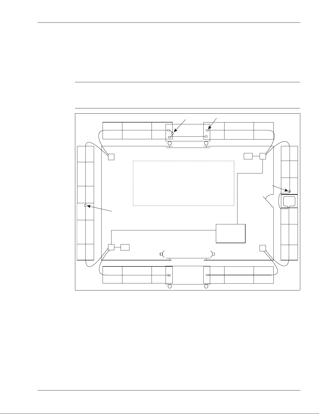
Site Survey
gate disconnect
terminator (typical)
sally port gate
proc #2
swinging gate
proc #1
proc #4
proc #3
power and data over
sensor cable connection
- app. max. fence length per cable 270 m (886 ft.)
microwave sensor
main
building
- drip loops at each splice/termination
- service loop every 50 m
- sensitivity loops at corner posts
sally port
gate
Z15Z12
Z10
48 VDC
48 VDC
Z1
Z2
Z3
Z4
Z5
Z6
Z7
Z8
Z9
Z11
Z13
Z14
Z16
Z17
Z18
Z19
Z20
data cable
data cable
- 19 FlexZone sensor zones (software defined)
- 1 UltraWave microwave zone (Z3)
power and data
over sensor cable
connection
Conduct a site survey to ensure that site conditions are suitable for a FlexZone sensor system.
The primary concern is the condition of the fences and gates. Use the results of the site survey to
create a site plan.
Note Sites that include a fence line that abuts the primary perimeter
Site Survey
fence can be vulnerable to climb over intrusions where the two
fences meet. To increase security in this situation, extend the
FlexZone cable for at least 2 m onto the abutting fence.
Indicate the following on the site plan:
• The locations of existing structures (include fences, gates, buildings, roads, etc.). Verify that
mounting surfaces comply with established standards for installation and stability.
• The locations of obstacles including vegetation and trees.
• The locations for the FlexZone components:
• Sensor cable - indicate the cable layout and zone boundaries for each sensor cable.
• Non-detecting cable - indicate the layout if non-detecting cable is required (at the
processor, or for a bypass).
FlexZone Product Guide Page 13
• Cable connectors - indicate the type of connection (splice, termination).
• FlexZone processors - note the addresses for network based processors.
Figure 5: Sample site plan
Page 14
Perimeter layout guidelines
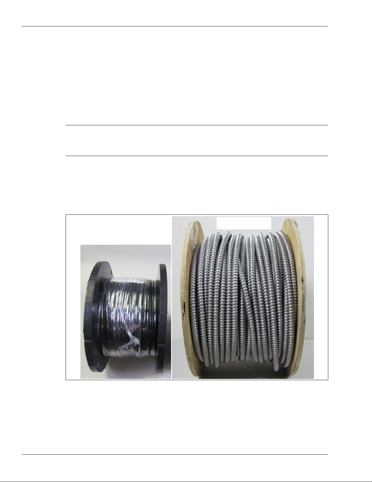
150 m (492 ft.) reel
FlexZone sensor cable
150 m (492 ft.) reel
armored sensor cable
• Power supply - indicate the type of power supply and the power distribution plan.
• Alarm communication wiring - relay output or network alarm communications.
• Power/data via sensor cables.
• The locations of other perimeter security equipment.
Perimeter layout guidelines
Note A FlexZone perimeter with 1, 2, or 3 processors can be fully closed (all
sensor cables connected through splices). A FlexZone perimeter with 4
or more processors must be open at the ends (first and last sensor
cables must be terminated).
FlexZone sensor cable
There are two types of FlexZone sensor cable, standard and armored. Both Standard FlexZone
sensor cable and Armored FlexZone sensor cable come in 150 m (492 ft.) and 220 m (722 ft.)
lengths. Two lengths can be spliced together to provide up to a 300 m (984 ft.) long sensor cable.
Figure 6: FlexZone and Armored FlexZone sensor cable reels
Page 14 FlexZone Product Guide
Page 15
Cable layout guidelines
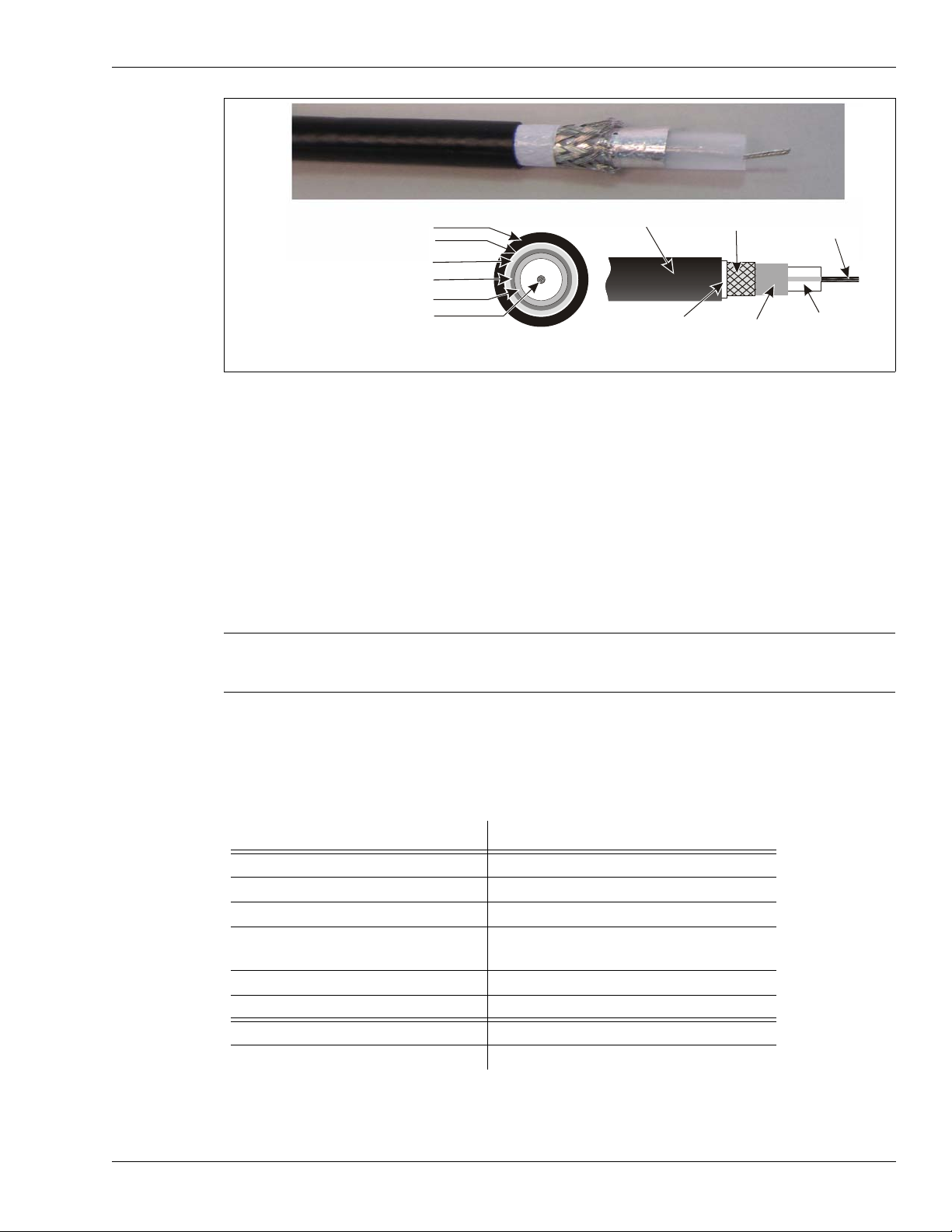
polyethylene
jacket
braided
shield
stranded center
conductor
clear tube
foil
clear tube
center conductor
aluminum foil
braided shield
outer black jacket
mylar film*
mylar film*
FlexZone sensor cable may include a mylar film between the outer black jacket and the braided shield.
The mylar film is used in the cable extrusion process and has no effect on the cable’s function.
*
• The full length of sensor cable must be mounted on the same type of surface.
• The maximum length of cable for each side of the processor is 300 meters (984 ft.).
• The smallest allowable bend radius for FlexZone sensor cable is 10 cm (4 in.).
• The smallest allowable bend radius for armored sensor cable is 15 cm (6 in.).
• Keep vertical drops of sensor cable to less than 1 m (3.3 ft.).
• The sensor cable should follow the ground contour to maintain a constant height above the
ground.
Perimeter layout guidelines
Figure 7: FlexZone sensor cable description
Note Senstar strongly recommends installing the sensor cable on the
secure side of the perimeter (the side of the fence opposite the
threat).
Cable length calculator (flexible fences)
Typically, fence coverage requires approximately 10% more cable than the linear fence length.
The following table provides a guideline for calculating the amount of sensor cable required for a
2.44 m (8 ft.) fence (in meters):
zone element required cable length (in meters)
start point + 1 m
service loops + 0.75 m X (linear cable length / 50)
zone demarcation loops + 3 m X number of zone boundaries
sensitivity loops + 3 m X number of corner and heavy
gauge posts
cable terminations and splices + 0.5 m each
linear fence length + _ _ _ _ _ (fence length)
required length of cable per pass = _ _ _ _ _ (total length)
total length X number of passes = _ _ _ _ _ cable length (max. 300 m)
FlexZone Product Guide Page 15
Page 16
Perimeter layout guidelines
max. h = 4.3 m (14 ft.)
1/2 h
1/2 h
1/3 h
1/3 h
1/3 h
single pass
double pass h > 4.3 (14 ft.)
1/4 h
1/4 h
1/4 h
1/4 h
double pass example
fences with a middle rail
h > 2 m (6.5 ft.)
double pass
rigid fences
flexible fences
30 cm (1 ft.)
above rail
single pass example
Rigid fences
Service loops, zone demarcation loops and sensitivity loops are not recommended on rigid fences.
Therefore, the length of cable required on a rigid fence is approximately the length of the fence
plus 5% overage (for each cable pass).
Fence height recommendations
The following cable spacing recommendations will provide a high probability of detection on well
maintained fences (see Figure 8:
• For flexible fences up to 4.3 meters (14 ft.) tall - a single pass of sensor cable at 1/2 the fence
• For flexible fences greater than 4.3 m tall - a double pass of sensor cable at 1/3 and 2/3 the
):
height.
fence height.
Note If the lower edge of the fence fabric is embedded in a concrete
footing, or below ground, an additional cable pass may be required
on the lower section of fence (a double pass at 1/3 and 2/3 fence
height).
Note If the fence framework includes an intermediate (middle) rail, it
may require a double cable pass, with one pass above the rail and
one pass below the rail.
Senstar recommends installing a single pass of cable 30 cm above
the middle rail on a small section of the fence (4 or 5 panels) and
then thoroughly testing the protected section to determine if a
single cable pass meets your detection requirements.
• For rigid fences (minimum recommended fence height 2 m, 6.5 ft.) - a double pass of sensor
cable along the top and bottom rails.
Non-detecting cable
For instances where the processor is located away from the protected fence, outdoor rated,
shielded 75 Ohm coaxial cable with a solid copper center conductor can be used as lead-in cable
(e.g., RG6). For cable bypasses along the perimeter, FlexZone sensor cable is used. The bypass
cable is set to inactive (Zone 0) in software and will not report sensor alarms. Non-detecting
FlexZone cable must be well secured to prevent any cable motion. The length of coaxial cable that
is used for lead-in must be deducted from the detecting cable length
(maximum cable length detecting plus non-detecting = 300 m, 984 ft.).
Figure 8: Cable pass recommendations
Page 16 FlexZone Product Guide
Page 17

Perimeter layout guidelines
Fence corners and heavier gauge posts (flexible fences)
Corner posts and heavier gauge support posts tend to dampen the fence’s vibration transmission
characteristics. Therefore, use cable loops at corner posts and heavy gauge support posts, to
increase the sensitivity. Each sensitivity loop requires approximately 3 m (10 ft.) of sensor cable
(see Figure 23:
).
Zone demarcation loops (flexible fences)
Zone demarcation loops may be used at software defined zone boundaries for improved location
accuracy. It is possible that an alarm that occurs very close to a software defined zone boundary
could be reported in the adjacent zone (± 3 m). Zone demarcation loops add extra sensor cable at
zone boundaries to help ensure that an alarm is reported in the zone in which it occurs. Allot 3 m
(10 ft.) for each zone to adjacent zone boundary (see Figure 24:
). Rather than using extra cable
for zone demarcation loops, overlapping CCTV coverage can provide visual assessment to verify
alarms and alarm location. When setting up the camera views, ensure that there is at least 6 m
(20 ft.) of overlapping coverage at each zone boundary.
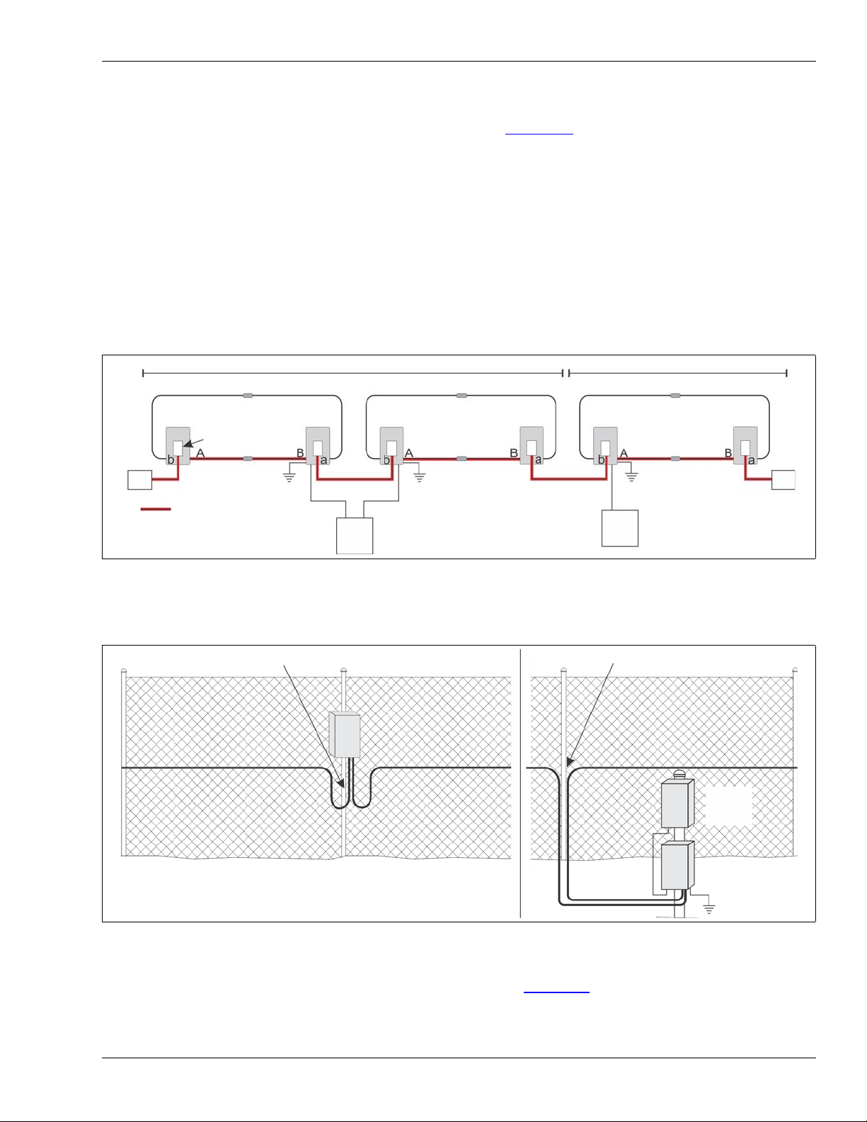
Service loops (flexible fences)
Service loops provide extra sensor cable along the fence to make cable repairs. Allot 75 cm
(30 in.) of cable each 50 m (164 ft.) for a service loop. Locate the U-shaped service loops at fence
posts (see Figure 25:
).
Drip loops (flexible fences)
Drip loops raise the connector above the sensor cable to prevent water from running along the
cable and accumulating in the enclosure. Drip loops also relieve strain resulting from temperature
changes that cause the cable to expand and contract. Form the drip loop by raising the connector
15 cm (6 in.) above the level of the cable run. Allot 50 cm (20 in.) of cable for each splice or
termination (see Figure 26:
).
Termination loops (flexible fences)
Termination loops provide extra sensor cable at the end of the protected section of the fence (at
the terminator) to make cable repairs or future sensor cable layout changes. The amount of cable
that can be used for a termination loop depends on the length of sensor cable (plus lead-in cable if
used) connected to the processor (side A or side B, maximum 300 m). Termination loops are
typically comprised of up to 5 coiled loops of sensor cable with a 60 cm (2 ft.) diameter.
Termination loops also include the length of 1 fence panel as the cable uses a double pass on the
final protected panel (see Figure 27:
).
Splice loops (flexible fences)
If there is extra sensor cable at the location of a cable splice, you can save the cable for cable
repairs or future sensor cable layout changes by forming a splice loop instead of cutting the cable
to length (see Figure 28:
). The maximum length of cable per side (300 m) cannot be exceeded,
but up to 10 m of cable can be coiled and attached to the fence at each side of a cable splice. A
10 m splice loop is comprised of 5 coiled loops of sensor cable with a 60 cm (2 ft.) diameter. Each
60 cm diameter coil of sensor cable contains approximately 2 m of cable.
FlexZone Product Guide Page 17
Page 18
Perimeter layout guidelines
1/3 fence height
1/3 fence height
1/3 fence height
A side cable
B side cable
identical features
300 m
matching
start points
matching
end points
terminator
terminator
matching
meter marks
(every 5 m)
Gate bypass
If there is a gate within a FlexZone sensor zone, you require a sufficient amount of inactive cable
to bypass the gate, even if the gate is protected by sensor cable. Secure the bypass cable and
bury it in PVC conduit. See Figure 48:
microwave system to provide security across the gate.
Armored cable
Armored cable is FlexZone sensor cable encased in a flexible metallic conduit. The armor protects
the sensor cable from damage and vandalism, as well as from the sun and weather. Steel cable
ties or wire ties are the recommended fasteners for armored cable. Armored cable is available in
lengths of 150 m (492 ft.). Two lengths can be spliced together to create a 300 m (984 ft.) cable.
Armored cable splices are enclosed inside metal condulet fittings (p/n G6KT0300).
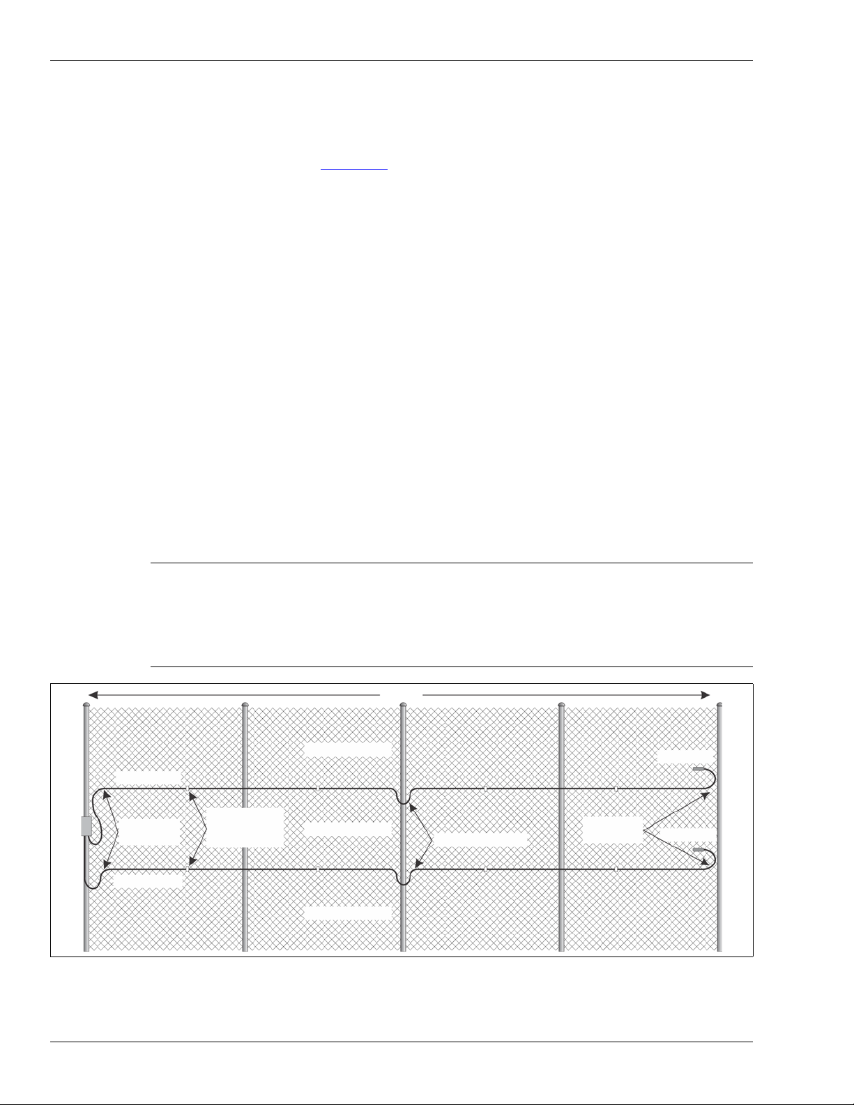
Double pass coverage
For FlexZone installations which require double passes of sensor cable, you use both cable sides
of a processor to provide software zoning and precise target location. To accomplish this the
processor is located at one end and the two sensor cable sides run parallel for up to 300 m along
the fence in an upper and lower cable pass. The ends of the two sensor cables are terminated or
spliced together. To enable precise target location, the detection start points of both cables must
match, and both cables must be of equal length and have identical features (e.g., service loops,
sensitivity loops, etc.). Each FlexZone processor can provide double pass coverage for up to
300 m of cable.
for an example of a bypassed gate, which uses a
Note Senstar recommends that both cables for a double pass installation be
laid out side by side on the ground beside the fence and marked with
tape at 5 m (16 ft.) intervals for the full length of the cable. This will help
ensure that the cables are properly length matched which is essential
for detection sensitivity and location accuracy in a double pass
installation
Figure 9: Single processor, double cable pass configuration
Page 18 FlexZone Product Guide
Page 19
Perimeter layout guidelines
300 m 300 m 300 m 300 m 300 m 300 m
power supply group
power supply group
48
VDC
48
VDC
NIC
processor
FlexZone
bi-directional data flow
power shared between
processors over both sensor cables
NIU
NIU
mmfo NIC
mmfo NIC
service loops for fence-mounted processor
non-detecting
no overlap for post-mounted processor
FlexZone
processor
48 VDC
power
supply
cable
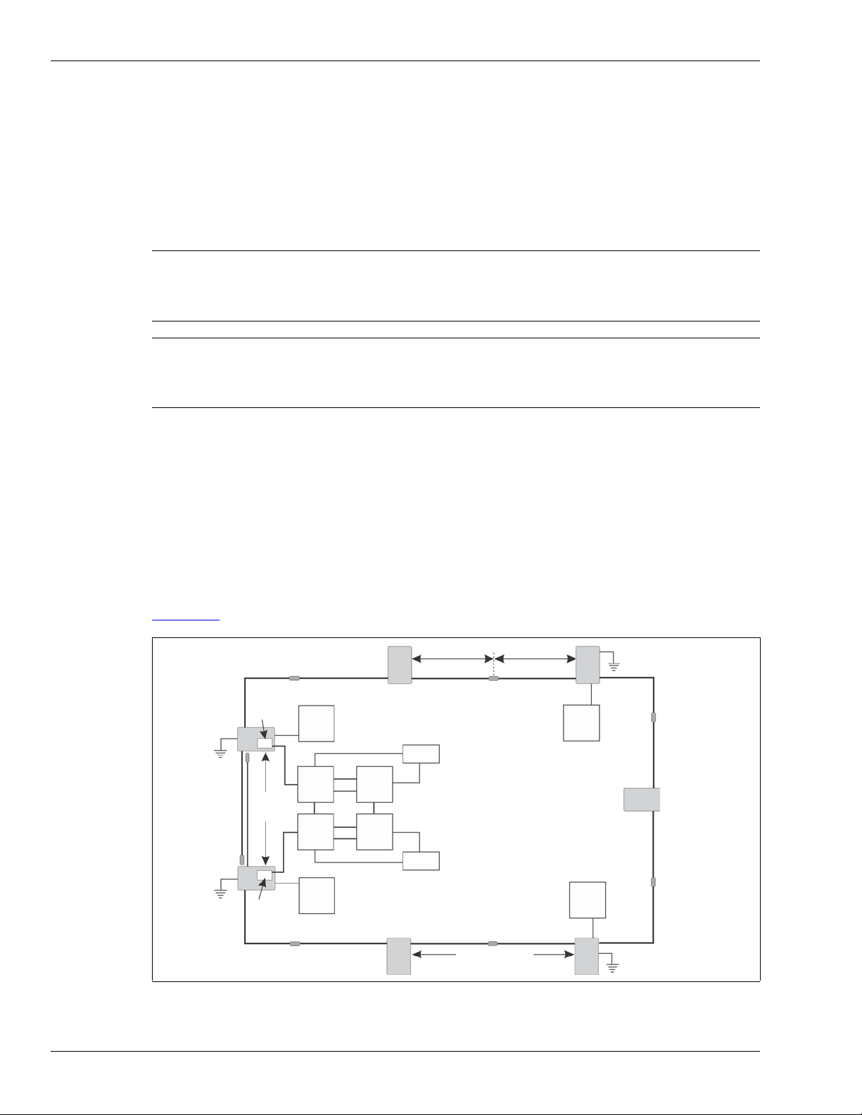
For a multi-processor FlexZone installation with a double pass of sensor cable using software
zoning, precise target locating, as well as power and data over the sensor cables there are a
number of requirements that must be observed. Figure 10:
illustrates a 1.8 km FlexZone
perimeter with six processors and a double pass of sensor cable.
• Each 48 VDC power supply can power to up to five processors over a maximum length of
1.5 km of sensor cable. The power supply must be connected to the central processor.
• The processors must be divided into blocks of two with network interface cards (NIC) carrying
the data between adjacent bocks (use multi-mode fiber optic NICs to isolate the sensor
blocks).
• The detection start points of each processor’s sensor cables must match, and both cables
must be of equal length and have identical features (e.g., service loops, sensitivity loops, zone
demarcation loops, etc.).
• Power flow, data flow and synchronization must be setup for each block of sensors via the
UCM.
Figure 10: Multi-processor, double pass ranging sensors with isolated power groups
Processor location guidelines
Figure 11: Processor location active cable start points
The FlexZone processor can be mounted outdoors on a post, either on, or separate from, the
fence on which the sensor cables are installed (see Figure 11:
for outdoor applications. The FlexZone processor can also be installed indoors or outdoors on a
flat stable surface. Post-mount hardware is supplied for post sizes from 4.5 cm to 12.7 cm
). A rigid fixed post is recommended
FlexZone Product Guide Page 19
Page 20

Perimeter layout guidelines
48
VDC
48
VDC
48
VDC
NIU
SMS
FlexZone processor
NIC
comm channel
splice/termination
cable side
sensor cable with power & data
network wiring
48 VDC power block
sync master
48 VDC power supply
processor network address
sensor cable
(1.75 in. to 5 in.). The hardware required for surface-mounting the processor is customer-supplied.
The FlexZone enclosure is hinged and includes a lockable latch (requires a Customer-supplied
pad lock).
Power source and wiring
The FlexZone processor can operate on a wide range of input voltages (12 to 48 VDC). The power
supply, the number of processors, and the lengths of the power cable runs will determine the
gauge of the power cable wiring that is required. In locations where AC power may not be stable or
reliable, an uninterruptable power supply (UPS) should be used for primary power. Assume a
maximum power consumption of 2.5 W per FlexZone processor (with NIC).
Power over the sensor cables
A group of up to five FlexZone processors can share power via the connected sensor cables. In
this case, the central processor is connected to a 48 VDC power supply. The sensor cables from
the central processor are connected to the two adjacent processors (one on each side). The
processor connected to the power supply requires a stable, low resistance earth ground
connection, which also serves as the ground reference for the connected block of processors.
Power and data distribution is setup via the UCM. Figure 12:
processor FlexZone perimeter with power and data over the sensor cables, and redundant Silver
Network communications.
illustrates a 7.2 km (4.5 mi.) 12
Auxiliary device output power
Processors that are receiving power over the sensor cables can supply up to 2 W of power to an
auxiliary security device through T4, the power connector. The output power is at the same voltage
as the received power input via the sensor cables. The minimum required voltage to enable power
over the sensor cables is 38 VDC. Figure 76:
processor supplying power and carrying alarm data for an UltraWave microwave sensor in both
Page 20 FlexZone Product Guide
Local and Remote control modes.
Figure 12: Power and data distribution via sensor cables
illustrates connection diagrams of a FlexZone
Page 21

Perimeter layout guidelines
Power over Ethernet
Silver Network based processors using Ethernet communications have the option of using Power
over Ethernet (Figure 73:
option requires a PoE class 3 switch that is located within 100 m (328 ft.) of the processor, and
minimum Category 5 network cable. Power over Ethernet is supplied to the processor’s Network
Interface card (NIC) and the power output on the NIC is connected to the power input on the
processor. Each processor receiving PoE requires an earth ground connection.
Note Senstar recommends using a fully managed PoE switch, to supply
Grounding considerations
A stable low resistance earth ground connection is required by each processor that is connected
directly to a power supply. Use a short length of heavy gauge copper wire to connect the ground
lug on the bottom of the processor’s enclosure to an approved earth ground. Processors receiving
PoE also require a ground connection via the enclosure ground lug. Processor’s receiving power
over the sensor cables do not require a direct ground connection. These processors use the
ground of the processor that is connected to the network power supply as their ground reference.
Consult the local electrical code for grounding information.
illustrates an Ethernet based Silver Network). To use this powering
power to a FlexZone processor.
Alarm data communications
Note Senstar recommends setting up a Silver Network, even when using
Local control mode. This enables remote calibration, maintenance
and diagnostic access to your FlexZone processors from a central
control facility.
There are two selectable control modes for the FlexZone processor’s inputs and outputs (I/O) local
control mode and remote control mode. You set the control mode in software, via the Universal
Configuration Module (UCM) which is a Windows-based software application. The default setting
is local control mode, in which the processor controls the on-board relays to signal alarm and
supervision conditions. In local control mode, the two Aux (auxiliary) inputs are self-test inputs to
the processor. In remote control mode, the alarm data is carried over the Silver Network to a host
security management system (SMS). Remote control mode enables the SMS to control the
processor’s relays as output points to operate other security equipment. The two Aux inputs
provide inputs to the host SMS for reporting the status of auxiliary devices. In both modes, you can
configure the processor’s input/output response according to your site-specific requirements.
• local control mode - hard-wired contact closure alarm data connections and self-test input
wiring connections are made between the processor and the annunciation equipment
(4 output relays, 2 self-test inputs) (the optional Relay Output card provides 4 additional
outputs for reporting alarm conditions)
• remote control mode - the alarm data communications are via the Silver Network - EIA-422
copper wire data paths or fiber optic cables connect one or two processors to the Network
Interface Unit (NIU), the remaining processors can be connected via EIA-422 wiring, fiber
optic cable, or data can be carried between processors via the sensor cables the 4 output
relays are available as output control points from the host system (the optional Relay Output
card provides 4 additional relays, which are also available as output control points), the 2
auxiliary device inputs are available for reporting the status of auxiliary equipment to the host
system (the optional dry contact input card provides 4 additional inputs, which are also
available for connecting auxiliary equipment to the host system)
FlexZone Product Guide Page 21
Page 22

Perimeter layout guidelines
Alarm communication options
• contact closure alarm communications (local control mode) up to 8 distinct alarm zones per
• built-in data communication network, secure data passes between processors over the sensor
• Silver Network data communications are daisy-chained to each processor around the
• Silver Network data communications are via Ethernet to each processor using category-5
Fail-safe relay operation
In the default configuration, the processor’s relays operate in fail-safe mode. During normal
operation, the relays latch in the non-alarm state. In the event of a total processor failure all relays
switch to the alarm state. Relays 1 and 2 indicate fail and supervision conditions and relays 3 and
4 report sensor alarms.
processor (requires optional ROC)
cables (one or two processors must have a Silver Network connection to the NIU.)
perimeter using either EIA-422 copper wire data paths or fiber optic cable (Silver Loop)
cable and a PoE switch (Silver Star)
Note You can use a combination of the above methods for powering and
data communications.
Note A Silver Network based processor can use local control mode to
operate its output relays and Aux inputs.
Relay Output Card
The relay output card (ROC) (P/N 00BA2500) includes four relays to supplement the four relays
available on the processor. In remote control mode, the host security management system
operates the ROC’s relays, as output control points, (e.g., to activate lights, doors, sirens, CCTV
equipment, etc.). You can configure the relays as latching (ON by command, OFF by command),
in flash mode (ON-OFF-ON-OFF, etc. by command, then OFF by command), or pulse mode (ON
for a period, then OFF). For flash and pulse modes, the Active/Inactive times are selectable.
Dry Contact Input Card
The dry contact input card (DRIC) (P/N 00BA2400) includes four inputs to supplement the two
inputs available on the processor. In remote control mode, the DRIC’s inputs connect auxiliary
devices to the host security management system (e.g., to report the status of other security
equipment such as a microwave or magnetic contact). The Filter Window parameter allows you to
set the time period for which an input must be active, before an event is reported.
Data over the sensor cables
A group of FlexZone processors can communicate via the connected sensor cables. In this case,
at least one processor requires a network interface card (NIC) to enable Silver Network
communications. The sensor cables from that processor are connected to the two adjacent
processors (one on each side). Processors that are using the sensor cables for data distribution
must be synchronized to prevent mutual interference.
To take advantage of the Silver Network’s redundant communications capability, two of the
connected processors require NICs and connections to a Network interface unit (NIU). In this way
network communications will travel in both directions over the sensor cables, so that a single break
in a sensor cable will not interrupt communications.
Page 22 FlexZone Product Guide
Page 23

Processor synchronization
A group of FlexZone processors that are connected through the sensor cables must be
synchronized to prevent mutual interference. For a fully closed 2 or 3 processor perimeter, one
processor must be set as the Sync Master for the group. The Sync Master generates a
synchronization signal and transmits the signal through its A-side sensor cable. The next
processor receives the Sync signal through its B-side cable, synchronizes itself accordingly and
then sends the Sync signal on to the next connected processor (A-side to B-side). The Sync
Master will not accept a signal from another processor and always restarts the synchronization
process. To set a processor as the Sync Master connect the UCM to the processor and uncheck
the Accept Sync Signal check box.
Note Only one processor in a connected group can be set as the Sync
Master or mutual interference will occur.
For an open loop sensor configuration where at least one sensor cable ends with a terminator (not
connected to another sensor cable) the synchronization process is automatic and requires no
configuration changes. Each processor that is set to Accept Sync Signal will receive the Sync
signal through its B-side cable, synchronize itself accordingly and then send the Sync signal on to
the next connected processor. By default, the processor on the end of the perimeter that is
connected to the next processor through its A-side cable will generate the Sync signal that starts
the synchronization cycle.
Perimeter layout guidelines
Alarm monitoring
Alarm monitoring is site specific and depends on whether you are using relay outputs for alarm
reporting (Local control mode) or Silver Network based alarm reporting (Remote control mode).
Each processor has four user-configurable Form C relay outputs. In Local control mode, the four
relays are used to signal alarm and supervision conditions. For network based processors, alarm
data is carried over the network cables and the four relays are available as output control points
from the security management system (SMS).
NM Mode
The FlexZone processor can be configured to report alarm and supervision conditions through the
UltraLink modular I/O system. In NM Mode, the UltraLink I/O processor acts as the Network
Manager, providing alarm outputs for a connected network of up to eight Silver devices. In NM
Mode, the Silver devices do not require a connection to a PC running Silver Network Manager
software. Sensor alarms and supervision conditions are assigned to UltraLink I/O outputs (relay or
open collector). When an alarm occurs on a connected sensor, the corresponding UltraLink I/O
output is activated (see NM Mode
Cable connectors
The splice kit is used to join two FlexZone cables together, and to join lead-in cable to sensor
cable. The splice kit is also used to make cable repairs. The termination kit is used in situations
where a FlexZone sensor cable is not connected to another FlexZone sensor cable. In this case,
the termination kit is connected to the end of the sensor cable to enable processor supervision.
The cable connectors are mounted horizontally on the fence using two cable ties.
on page 99 for additional details).
Note Senstar recommends limiting cable repair splices to one splice per
150 m (492 ft.) cable length.
FlexZone Product Guide Page 23
Page 24
High security installations
150 m (max.)
150 m (max.)
48
VDC
48
VDC
48
VDC
48
VDC
300 m (max.)
NIU
NIC
NIC
UPS
UPS
NIU
NM
SMS
NM
SMS
P1
P2
P3
P4
P5
P6
P7
300 m
(max.)
High security installations
The FlexZone sensor can provide redundancy for high-security installations, providing certain
rules are followed. If these rules are followed, then the system will continue to provide perimeter
detection even if one processor fails, or a sensor cable is cut or if one power supply fails. With this
configuration, each 300 m of sensor cable is monitored simultaneously, by two processors.
Note If a sensor cable is cut, location accuracy may be diminished and an
increased system noise level (clutter) and NAR may occur. In the event
of a cut cable, repairs must be made as quickly as possible to return the
system to its full detection capabilities.
Note A fully redundant system requires that there be no single point of failure.
Therefore, the system requires two Network Interface Units, two
Network Manager PCs, two Security Management System PCs (NM
and SMS can reside on one PC) and two UPS systems.
High-security installation rules
• maximum sensor cable length for one side of a processor is 150 m (492 ft.) except terminated
open ends of perimeter (max 300 m)
• maximum length of sensor cable between 2 processors is 300 m (984 ft.)
• a minimum of two 48 VDC power supplies (depending on total number of processors)
• power supplies must be connected to processors on the ends of the perimeter
• two Silver Network connections to two Network Manager PCs at opposite ends of the loop,
OR, star network configuration setup using PoE with redundant switches
Figure 13:
Page 24 FlexZone Product Guide
shows a seven processor high-security perimeter up to 2.1 km (1.3 mi.) in length.
Figure 13: High-security redundancy (2.1 km example)
Page 25

2 Installation
Installing the sensor cable
CAUTION FlexZone sensor cable must be conditioned before it is attached to
the fence.
CAUTION When installing FlexZone sensor cable during periods of freezing
weather (below 0º C, 32º F) extra care must be taken as the sensor
cable is less flexible, and the polypropylene cable ties can be prone to
failure.
Cable handling rules
The FlexZone sensor cable converts minute vibrations in the fence fabric into electrical signals.
Any damage to the cable from mishandling or poor installation practices will have a negative effect
on the system’s performance.
• DO NOT bend, twist, jerk, knot, or kink the sensor cable.
• DO NOT nick or scrape the sensor cable’s outer jacket.
• Avoid tight turns in the sensor cable, the minimum bend radius for FlexZone sensor cable is
10 cm (4 in.) and for armored FlexZone cable is 15 cm (6 in.).
• DO NOT place objects on the sensor cable or allow anyone to stand or walk on the cable.
• DO NOT allow the cable to fall off the side of the cable reel.
• DO NOT apply excessive tension to the sensor cable at any time.
• When using cable ties to attach the sensor cable to a fence, install the ties by hand and pull
them hand-tight until snug.
• DO NOT use mechanical tighteners to attach cable ties to a fence.
• DO NOT allow the sensor cable to be pinched between the fence and a fence post, or any
other object.
• Keep the ends of the sensor cable clean and dry. If water enters the loose tube it can cause
corrosion and potentially freeze in the winter, which will have a negative effect on sensitivity.
Note The number of cable passes required on a fence depends on the
height of the fence, the type of fence, and the required level of
security (see Fence height recommendations
FlexZone Product Guide Page 25
on page 16).
Page 26
Installing the sensor cable
expose 30 cm (12 in.) of the center conductor
ensure the exposed center conductor
is free to extend or retract
30 cm
(12 in.)
remove 45 cm (18 in.) of the armored jacket and
expose 30 cm (12 in.) of the center conductor
armored cable
30 cm
(12 in.)
15 cm
(6 in.)
NOT bent
NOT twisted
NOT flattened
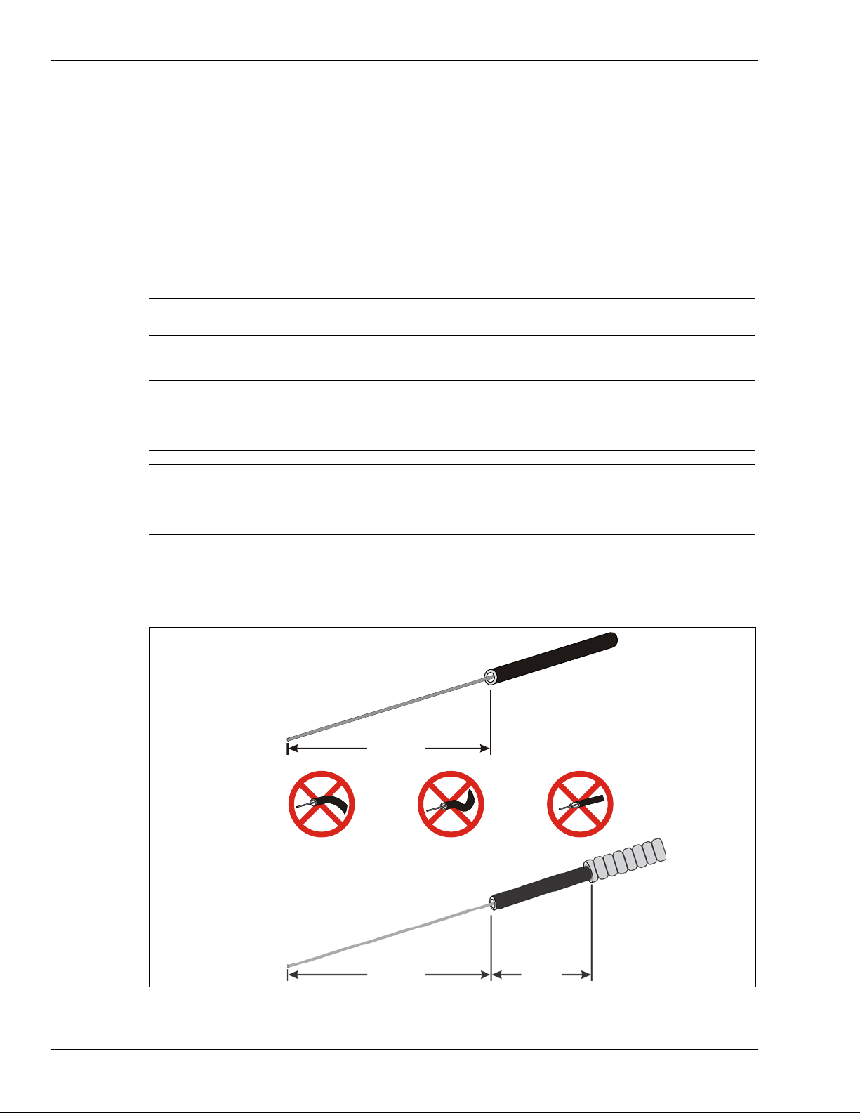
FlexZone sensor cable conditioning
Before installing FlexZone sensor cable, the cable must be conditioned. Prior to conditioning, there
may be excess center conductor in the cable, or the center conductor may be adhered to the cable
side walls after the manufacturing process. Conditioning frees the center conductor and
maximizes its movement, thereby providing the greatest sensitivity. Cable conditioning is best
done by two people and typically takes about 10 minutes for a 150 m sensor cable. FlexZone
cable conditioning can be done by a single person, but it can take significantly longer to complete
due to repeatedly walking back and forth.
Cable conditioning procedure (part 1 - cable preparation)
1. Dispense the sensor cable alongside the fence in a long straight line.
Note This procedure applies to both standard FlexZone sensor cable and
armored FlexZone sensor cable.
Note If site conditions prevent the cable from being laid out in a straight line,
minimize the number of turns and use as large a turn radius as
possible. Turns in the cable will require an increase in the amount of
pulling force needed to move the center conductor back and forth.
Note If the cable is moved to a more open area to be conditioned, move it
2. Carefully remove 30 cm (12 in.) of the black outer jacket, shield and clear tube to expose
30 cm of the center conductor at both ends of the cable. For armored cable, remove 45 cm
(18 in.) of the armor from each end of the cable, then expose 30 cm (12 in.) of center
conductor at each end.
carefully back to the installation location following the process. Avoid
using excessive pulling force and do not pull the cable around corners
or fence posts when it is repositioned.
Page 26 FlexZone Product Guide
Figure 14: Exposing the center conductor
Page 27
Installing the sensor cable
black outer jacket
use the loop to apply tension to the center conductor
second person
first person
hold the cable and apply light
hold the cable by the black jacket
pulling tension to the center conductor
(apply no tension)
3. Check the ends of the cable to verify that the center conductor is free to retract or extend
(i.e., the center conductor is straight and the cable end is not pinched, flattened, twisted, bent,
or distorted). If an end is damaged enough to prevent the free movement of the center
conductor, cut off the damaged section and re-strip the cable.
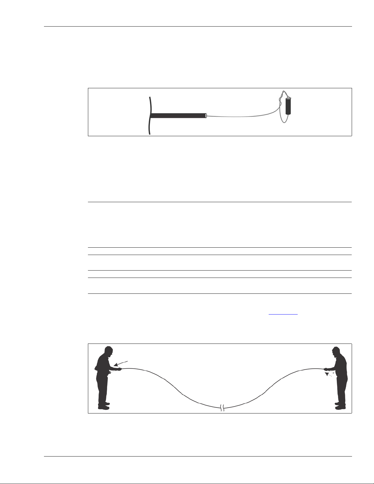
4. At both ends of the cable, tie a loop through a 2.5 cm (1 in.) piece of the black jacket, to
prevent the center conductor from retracting into the cable during the conditioning procedure.
Figure 15: Securing the center conductor
Cable conditioning procedure (part 2 - cable flossing)
Pull the cable by the black jacket to remove any slack and then use a “flossing” motion to pull the
center conductor back and forth to ensure the center conductor is floating freely over the full length
of the sensor cable.
Note Initially, there may be resistance as well as some “stretching” as the
center conductor is freed inside the cable (i.e., the center conductor
pulls out at one end but remains the same length at the other). Once the
center conductor moves back and forth easily so that pulling it out
15 cm (6 in.) at one end causes it to retract 15 cm at the other end, the
conditioning is complete.
Note You can hear the motion of the floating center conductor as it rattles
when you tap a properly conditioned sensor cable.
Note Maintain a firm grip and consistent pulling tension, and keep the sensor
cable taut and in-line during the cable conditioning procedure.
1. The first person begins by holding the cable by the black jacket with one hand and applying
light pulling tension to the center conductor with the other (see Figure 16:
).
The second person holds the cable by the black jacket and allows the center conductor to
move freely (no tension applied).
The first person stops pulling when they encounter an
increase in resistance or the center conductor can be pulled no further.
FlexZone Product Guide Page 27
Figure 16: FlexZone cable conditioning (part 2 cable flossing)
Page 28
Installing the sensor cable
apply light pulling tension
to the center conductor
hold the cable
second person
first person
by the black jacket
second person
first person
pulling tension to the center conductor
hold the cable and apply light
hold the cable by the black jacket
(apply no tension)
apply light pulling tension
to the center conductor
hold the cable
second person
first person
by the black jacket
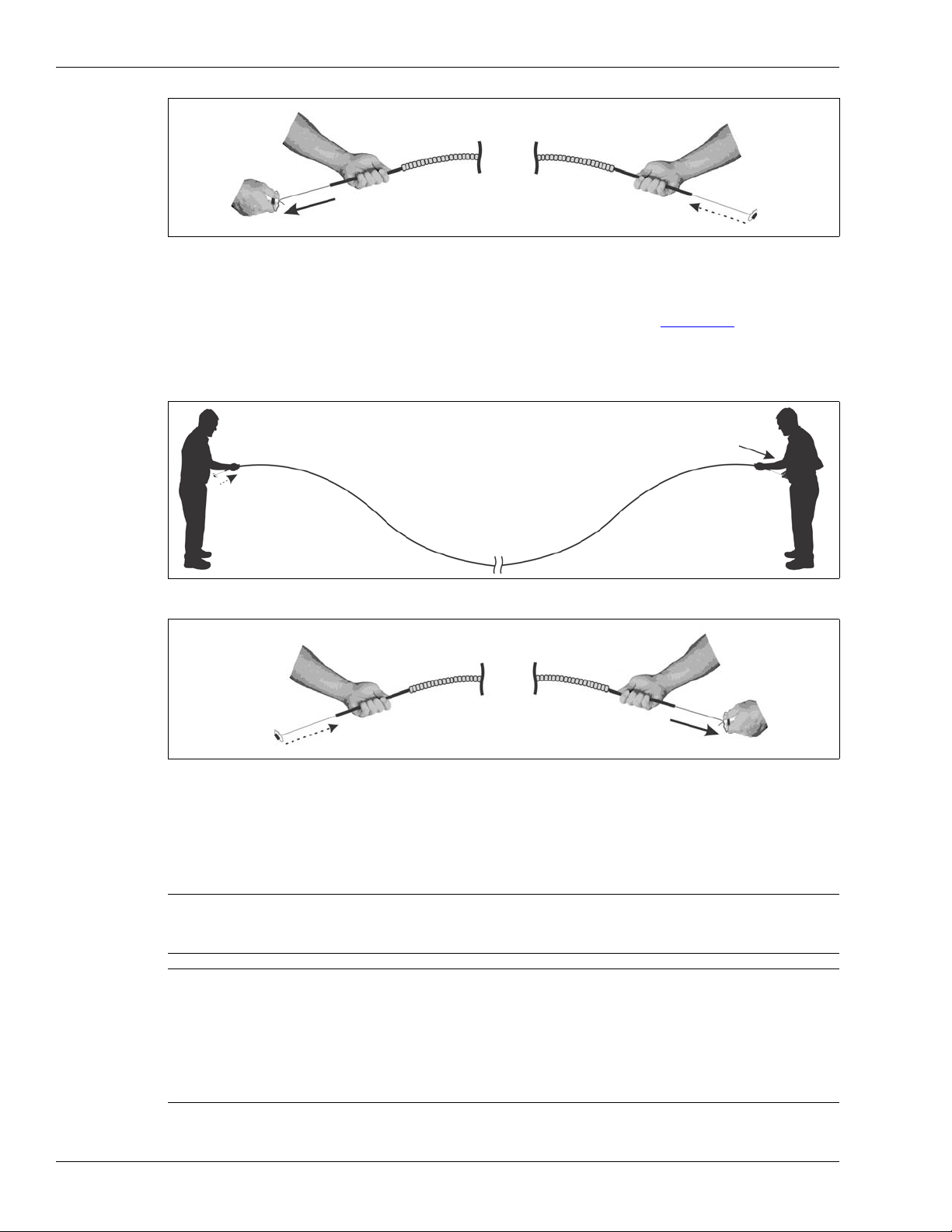
2. When the second person observes that the center conductor has been pulled to its limit, the
Figure 17: FlexZone armored cable conditioning (part 2 cable flossing)
second person waits 10 seconds and then applies light pulling tension to the center conductor
while holding the cable by the black jacket with the other hand (see Figure 18:
).
The first person holds the cable by the black jacket and allows the center conductor to move
freely (no tension applied).
in resistance or the center conductor can be pulled no further.
The second person stops pulling when they encounter an increase
Figure 18: FlexZone cable conditioning (part 2 cable flossing)
Figure 19: FlexZone armored cable conditioning (part 2 cable flossing)
3. Continue this flossing motion back and forth until the center conductor moves easily with very
little resistance.
4. When the conditioning procedure is complete, release the tension on the center conductor,
and cut off any center conductor that was damaged during conditioning.
Note When conditioning is complete, the center conductor slides easily in both
directions, and it may extend an additional 15 to 30 cm out of the cable
jacket at both ends.
Note If the center conductor does not move back and forth easily (or at all)
during the flossing process, straighten any turns in the cable (relocate the
cable if necessary). Have one person grip the cable at one end and apply
light tension to the center conductor while the second person walks the
length of the cable from the other end shaking and tapping the cable.
Page 28 FlexZone Product Guide
Next, repeat the cable flossing procedure until the center conductor
moves freely and easily.
Page 29
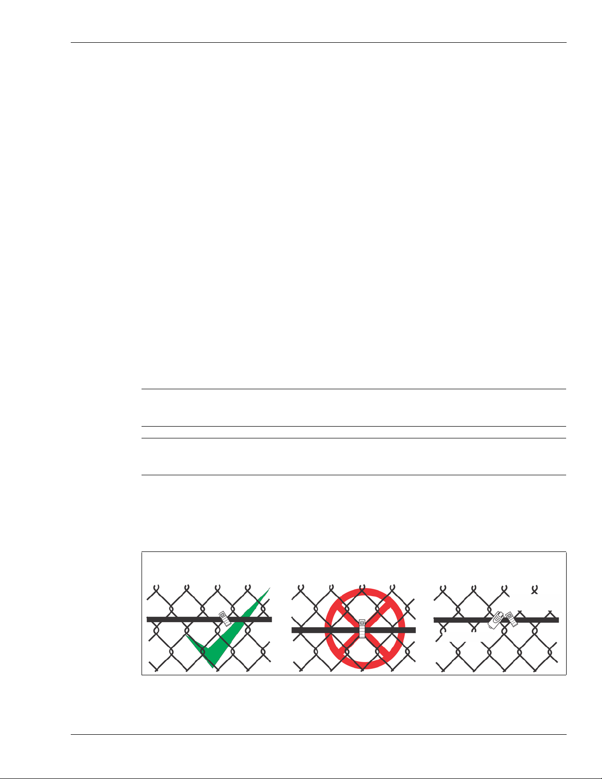
Installing cable on chain-link fences
attach the cable to the fence fabric
in the middle of a fence wire
DO NOT attach the cable to the fence
fabric at the junction of 2 fence wires
use 2 steel cable ties on each fence
polypropylene
cable tie
steel cable tie
panel in addition to the polypropylene
ties for added security
• Attach the sensor cable to the secure side of the fence (the side opposite the threat).
• Secure the cable to the fence so that it maintains a constant height above ground (i.e., if the
fence steps up a hill, the cable should also step up the hill).
• Use UV resistant polypropylene cable ties spaced 25 to 30 cm (10 to 12 in.) apart to attach the
sensor cable to the fence.
• Pull the cable ties until they are hand tight and the cable is snug to the fence.
• Attach the cable ties to the center of a link (one wire) NOT at the junction of two fence wires.
• Optionally, for increased security use two steel cable ties per fence panel in addition to the
polypropylene cable ties. Hand-tighten the steel cable tie on a fence wire adjacent to a
polypropylene cable tie to hold the cable snuggly against the fence without crushing or
distorting the sensor cable in any way. DO NOT use a mechanical tightening device.
• DO NOT attach the sensor cable to tension wires.
• Attach the sensor cable at least 30 cm (1 ft.) away from horizontal support bars and other
cables.
• For a single cable pass, attach the sensor wire to the middle of the fence.
• Avoid vertical drops greater than 1 m (3.3 ft.) when installing FlexZone sensor cable. Vertical
drops of 1 m or more can result in an area with excessive sensitivity, which may cause
nuisance alarms. Install vertical cable drops that are greater than 1 m with a minimum 15º
slope.
• Use armored sensor cable if the cable is being installed in an area where it may be prone to
damage from vandalism, equipment, or materials.
• Keep the ends of the cable clean and dry.
Installing the sensor cable
Note Galvanized fences occasionally have rough patches from the
galvanizing process. Avoid attaching the sensor cable at locations
where rough galvanizing can potentially damage the cable.
Note Tap the sensor cable occasionally as you attach it to the fence and
listen for the rattle of the floating center conductor to ensure the cable is
properly conditioned.
Installing cable ties
• Using UV resistant polypropylene cable ties, secure the cable to the fence fabric at the
midpoint of the chain-link. Install the cable ties by hand, tightening them enough to hold the
cable securely against the fence.
Figure 20: Securing cable to a chain-link fence
FlexZone Product Guide Page 29
Page 30
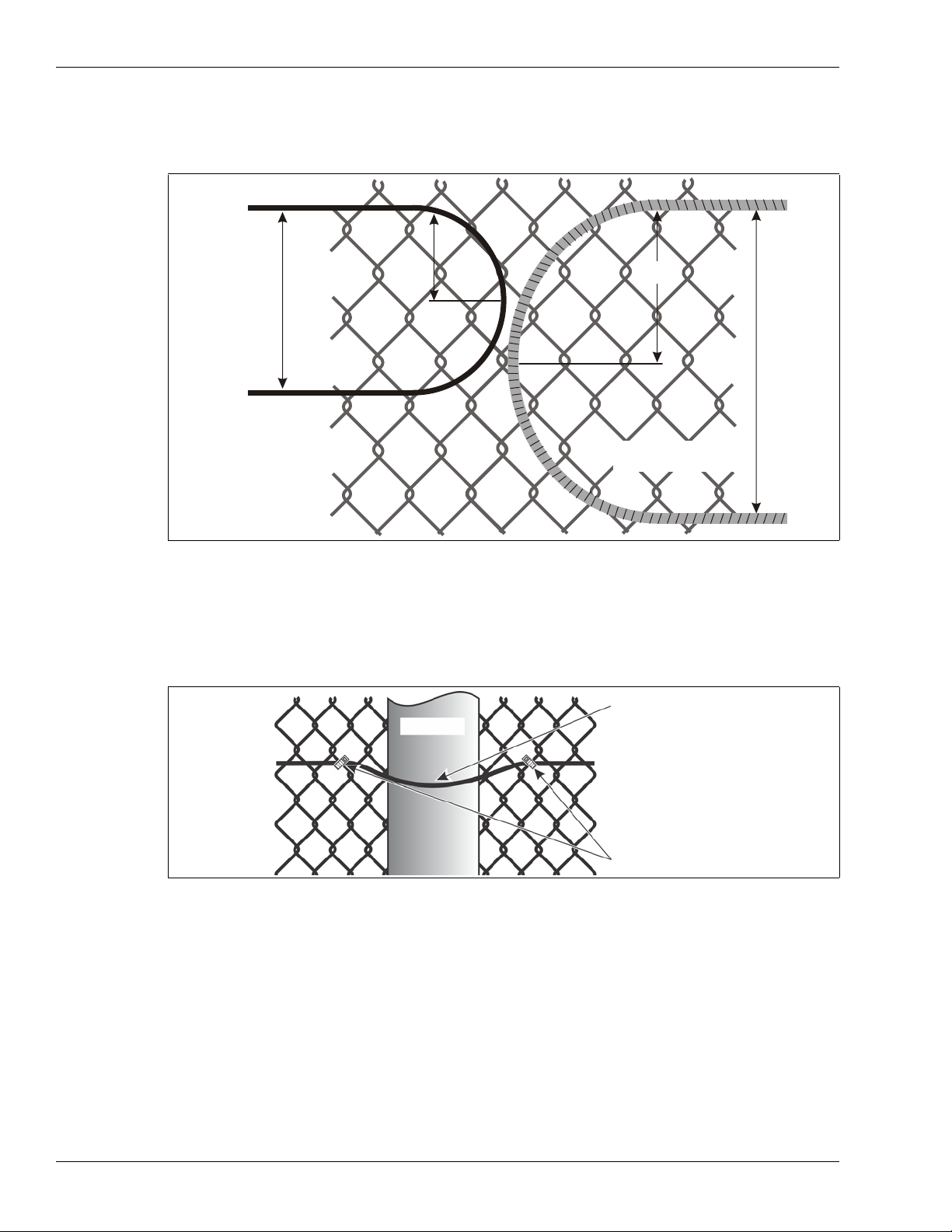
Installing the sensor cable
20 cm
15 cm
30 cm
armored sensor cable
FlexZone sensor cable
10 cm
(8 in.)
(4 in.)
(6 in.)
(1 ft.)
secure the cable at both sides
sensor cable
fence post
the cable should be snug
against the fence post
(not stretched tightly)
of each fence post
Bend radius
• The smallest allowable radius for FlexZone sensor cable is 10 cm (4 in.).
• The smallest allowable radius for armored sensor cable is 15 cm (6 in.).
Figure 21: Smallest allowable bend radius
At fence posts
• Secure the cable at both sides of each fence post so the cable is in contact with the post. The
cable should have enough slack so that it is not stretched tightly or flattened. Once cable ties
are attached at each side of the post, it should be easy to move the sensor cable with your
fingertips.
Figure 22: Cable at fence posts
At corners or heavy gauge posts
Install sensitivity loops at all fence corners and at any heavy gauge fence posts.
Page 30 FlexZone Product Guide
Page 31

Installing the sensor cable
sensor cable
chain-link fence
1 m
(3.3 ft.)
0.5 m
(20 in.)
0.5 m
(20 in.)
zone demarcation loops
inactive bypass cable
Zone n
Zone n+1
Zone n+2
(assigned to Zone 0)
zone demarcation loops
protected gates
min. 15º slope
Figure 23: Sensitivity loops at corner and at heavy gauge posts
At software defined zone boundaries
• Optionally, install zone demarcation loops at soft zone boundaries for increased zone
isolation. The extra cable helps ensure that valid targets are located accurately in the correct
zone. See Figure 23:
See Figure 24:
for sensitivity loop and zone demarcation loop layout recommendations.
for an illustration of how to use zone demarcation loops.
FlexZone Product Guide Page 31
Figure 24: Optional Zone demarcation loops for software defined zone boundaries (protected gate access)
Service loops
• Install U-shaped service loops approximately 50 m (164 ft.) apart along the sensor cable run.
The loop should measure 30 to 45 cm from top to bottom. Install service loops at fence posts.
• For a double cable pass create two equally spaced service loops in the same manner as for a
single cable pass.
Page 32

Installing the sensor cable
service loop for cable repair
30 to 45 cm
(12 to 18 in.)
15 cm (6 in.)
20 cm (8 in.)
splice connector
terminator
Drip loops
• Install drip loops at every cable connector. Form the drip loop by raising the connector above
Figure 25: Single cable pass service loop
the level of the cable run before securing it, horizontally, to the fence fabric (15 cm {6 in.} for
splices, or 20 cm {8 in.} for terminations).
Figure 26: Drip loops
Termination loops
• If there is excess cable at a terminator location, loop the cable back for one fence panel and
form a termination loop by creating up to 5 loops of sensor cable with a 60 cm (2 ft.) diameter.
This will provide up to 13 m of sensor cable that can be used for future repairs or for changes
in the sensor cable layout. Figure 27:
termination loop.
illustrates the recommended configuration for a
Page 32 FlexZone Product Guide
Page 33

Installing the sensor cable
termination service loop
(5 loops, 60 cm diameter)
terminator
end of detecting
cable (software)
up to 10 m of cable
splice-connection
splice point service loops
(5 loops, 60 cm diameter)
up to 10 m of cable
Figure 27: Termination loop example
Splice loops
• If there is excess cable at a cable splice location, form splice service loops by creating up to 5
loops of sensor cable with a 60 cm (2 ft.) diameter. This will provide up to 10 m of sensor cable
at each side of the splice that can be used for future repairs or for changes in the sensor cable
layout. Figure 28:
illustrates the recommended configuration for splice loops.
Figure 28: Splice loop example
FlexZone Product Guide Page 33
Page 34

Installing the sensor cable
start point post
second post
third post
spacing
25 - 30 cm (10 - 12 in.)
Installing cable on chain-link
1. Dispense the sensor cable alongside the installation location on the secure side of the fence.
2. Beginning at the start point, attach the sensor cable to the fence fabric at point a (see Figure
3. Hold the sensor cable straight and level along the fence while you attach the cable to the
4. Return to the start point and install cable ties every 25 to 30 cm (10 to 12 in.) along the first
5. Attach the cable to the fence beside the second post at point i. Ensure the cable is not
6. Hold the sensor cable straight and level along the fence while you attach the cable to the
7. Return to the second post and install cable ties every 25 to 30 cm (10 to 12 in.) along the
8. Continue this procedure, one fence panel at a time, until the cable is fully installed.
9. Verify that there are no slack or loose sections of cable, and that the cable ties are properly
Figure 29: Installation procedure diagram
Do not allow the sensor cable to fall off the spool, as it may twist and kink. (The FlexZone
cable should have been deployed at the installation location for the conditioning procedure.)
29: ). Leave enough extra sensor cable at this point to install a splice kit, or to connect the
sensor cable to the processor (refer to the site plan for the processor’s installation location).
fence fabric beside the second post at point b. Ensure that there is no slack in the sensor
cable.
fence panel at points c to h.
stretched tightly, but that it is snug across the fence post.
fence fabric beside the third post at point j.
second fence panel at points k to p.
tightened. Trim and properly discard the ends of the cable ties.
Page 34 FlexZone Product Guide
Installing cable on welded-mesh fence
Note Follow the installation instructions and use the height
recommendations for chain-link fences when installing sensor
• Install the sensor cable on the secure side of the fence (the side opposite the threat).
cable on welded-mesh fence.
• Sensor cable being installed on the same side of the fence as the horizontal wires should be
placed directly below the horizontal wire and attached every 25 cm (10 in.).
• Sensor cable being installed on the opposite side of the fence as the horizontal wires should
be attached at the intersection points of the two wires every 25 cm (10 in.).
Page 35

Figure 30: Welded-mesh fence
sensor cable on the same side as the horizontal wires
sensor cable on the opposite side of the horizontal wires
sensor cable
cable tie
attach sensor cable snugly
to the horizontal wire
attach sensor cable
to the intersection of
the horizontal and
vertical wires
sensor cable
cable tie
A side cable
B side cable
matching
start points
e.g., 2 m
cable tie spacing
consistent for
both passes
service loop
identical
features
zone demarcation loop
matching
end points at
terminators
e.g., 275 m
max. 300 m
5 m tape
markers for
length matching
Double pass cable installation
For double cable pass installation use both sides of one processor for the upper and lower cable
runs. The FlexZone sensor monitors the received signals from both sensor cables to determine
intrusion activity. Therefore, it is critical that the features and lengths of both cables are properly
matched. Figure 31:
multiple processor installations the upper cables and lower cables of two processors are joined by
spice kits (see Figure 10:
29 to attach FlexZone sensor cable in a double pass configuration. The cable spacing for a double
pass configuration is 1/3 the fence height for the lower pass and 2/3 the fence height for the upper
pass. If the double pass is required because the fence has a middle rail, then the lower pass
should be 1/2 way between the middle rail and the ground, while the upper pass should be 1/2 way
between the middle rail and the top of the fence.
illustrates the double pass concept for a single processor installation. For
). Refer to Figure 31: and Installing cable on chain-link fences on page
Installing the sensor cable
Note Lay the two cables side by side on the ground beside the fence after the
FlexZone Product Guide Page 35
conditioning procedure, and mark the two cables with tape every 5 m
(16 ft.). This will facilitate length matching during cable installation.
Figure 31: Double pass cable installation
Page 36

Installing the sensor cable
custom cable clamps
FlexZone sensor cable
Impasse
®
II high-security
palisade fence
shield
shield
shield
center conductor
center conductor center conductor
splice CCA (G6KT0101)
terminator CCA (G6KT0201)
Installing cable on rigid fences
The technique used to install sensor cable on rigid fences depends on the type, and brand, of
fence. In some instances, cable ties are used to attach the sensor cable. Some manufacturers
offer cable clamps that are specific to their fence type (see Figure 32:
loops and zone demarcation loops are not recommended on rigid fence types. Refer to application
note G6DA0309-001 (Using FlexZone on palisade fences) if you are considering installing the
FlexZone sensor on a rigid fence type.
). Service loops, sensitivity
Sensor cable connections
Figure 32: Palisade fence with FlexZone sensor cable on top rail
There are three FlexZone sensor cable connections: processor connections, splices and
terminations. The sensor cable to processor connections are made on removable terminal blocks,
which plug into connectors on the processor. Splice and termination connections are made on
terminal blocks that are mounted on small circuit card assemblies (CCA).
Figure 33: Splice CCA & Terminator CCA
TIP Follow the silk screening when connecting the sensor cable to the CCA.
Note If there is excess sensor cable at the location of a cable splice or
termination, you can coil up to 10 m of sensor cable and attach it to the
fence. Then cut the cable to the proper length for the connection.
Page 36 FlexZone Product Guide
Page 37

Installing the sensor cable
Note Keep the sensor cable and enclosure clean and dry during installation.
Cable preparation (all connections)
1. Cut the sensor cable to the correct length for the application:
• For splice connections, cut the sensor cable 15 cm (6 in.) past the specified location of the
splice.
• For terminations, cut the cable 0.5 m (20 in.) past the specified termination point.
• For processor connections, pull approximately 60 cm (2 ft.) of sensor cable into the
enclosure through the two cable glands on the right side of the enclosure.
2. Carefully, remove 20 mm (0.8 in.) of the outer jacket and the mylar film from the end of the
sensor cable. DO NOT nick the braided shield.
TIP Cut only part way into the outer jacket and then twist the two sections
apart.
Figure 34: Preparing FlexZone sensor cable step 2
3. Separate the strands of the exposed braided shield, and twist the strands into two separate
conductors, on opposite sides of the cable.
4. Peel back and remove the foil covering flush with the black outer jacket.
Figure 35: Preparing FlexZone sensor cable steps 3 & 4
5. Trim back the clear tube to a length of 5 mm (1/5 in.) by carefully removing app. 15 mm
(3/5 in.) from the end of the cable. DO NOT nick the center conductor.
6. Bend and form the two sections of twisted braided shield into conductors that are parallel with,
and separated from, the center conductor by 5 mm (1/5 in.) on opposite sides of the cable.
FlexZone Product Guide Page 37
Page 38

Installing the sensor cable
A Side
B Side
Figure 36: Preparing FlexZone sensor cable steps 5 & 6
Note For cable splices proceed to Sensor cable splices
For terminations proceed to Sensor cable terminations
on page 39.
on page 40.
Processor connections
See Cable preparation (all connections) on page 37 for steps 1 - 6.
7. Trim the twisted braided shields and the center conductor to a length of 6 mm (1/4 in.) past the
end of the clear tube.
8. Remove the A Side terminal block from T9. Connect the A Side cable to the three position
terminal block by inserting the center conductor and the two twisted braided shield conductors
into the terminal block and tightening the screws. The center conductor goes into the center
(second) terminal.
Figure 37: Processor sensor cable connections steps 7 & 8
9. Repeat this procedure for the B Side sensor cable.
10. Pull the sensor cables back out through the cable glands until they are the correct length to
plug into T9 (A Side to terminals 1, 2, 3; B Side to terminals 4, 5, 6). Tighten the cable glands.
Figure 38: Processor sensor cable connections step 10
Page 38 FlexZone Product Guide
Page 39

Installing the sensor cable
45º
insert the twisted braided shields into opposing
insert the center conductors into opposing
terminals and tighten the screws
terminals and tighten the screws
Sensor cable splices
See Cable preparation (all connections) on page 37 for steps 1 - 6.
7. For splice connections bend and form the section of twisted braided shield on the left side of
the cable into a conductor that is parallel with, and separated from, the center conductor by
5 mm (1/5 in.). Trim the second section of twisted braided shield flush with the black jacket.
8. Trim the twisted braided shield and center conductor to a length of 6 mm (1/4 in.) past the
clear tube.
Figure 39: Sensor cable splices steps 7 & 8
9. Repeat this procedure for the second sensor cable.
10. Insert the center conductors into opposing terminals on the splice circuit card assembly (CCA)
and tighten the screws. Insert the twisted braided shields into the adjacent opposing terminals
on the splice CCA, and tighten the screws.
Figure 40: Sensor cable splices steps 10 & 11
11. Secure both sensor cables to the splice CCA using the supplied cable ties. Ensure that the
heads of the cable ties are all on the same side of the CCA and that they are at a 45º angle
from the flat plane of the CCA.
12. Line up the splice CCA so it is centered between the dual cable guide bars, and press the
assembly firmly into the gel snap enclosure. Press the sensor cable into the cable guide bars.
DO NOT remove the protective gel inside the enclosure.
13. Snap the enclosure shut ensuring that both tabs are securely locked in the slots.
Note The weather-proofing protective gel should be oozing out of the gel
snap enclosure.
FlexZone Product Guide Page 39
Page 40

Installing the sensor cable
dual cable guide bars
dual cable guide bars
center the splice CCA between the dual cable guide bars
locking tabs in slots
15 cm (6 in.)
14. Form two 15 cm (6 in.) drip loops and attach the splice enclosure to the fence.
Figure 41: Sensor cable splices steps 12 & 13
Figure 42: Mounting the splice enclosure
Sensor cable terminations
See Cable preparation (all connections) on page 37 for steps 1 - 6.
7. For terminations bend and form the section of twisted braided shield on the left side of the
cable into a conductor that is parallel with, and separated from, the center conductor by
5 mm (1/5 in.). Trim the second section of twisted braided shield flush with the black jacket.
Figure 43: Sensor cable terminations steps 7 & 8
8. Trim the twisted braided shield and center conductor to a length of 6 mm (1/4 in.) past the
clear tube.
9. Insert the center conductor into the right side terminal (+) and tighten the screw. Insert the
twisted braided shield into the left hand terminal (-) and tighten the screw. Observe polarity.
10. Secure the sensor cable to the termination CCA using the supplied cable ties. Ensure that the
heads of the cable ties are both on the same side of the CCA and that they are at a 45º angle
from the flat plane of the CCA.
Page 40 FlexZone Product Guide
Page 41

Installing the sensor cable
45º
shield
center conductor
dual cable guide bars
dual cable guide bars
center the terminator CCA between the dual cable guide bars
locking tabs in slots
20 cm (8 in.)
Figure 44: Sensor cable terminations steps 9 & 10
11. Line up the termination CCA so it is centered between the dual cable guide bars, and press
the assembly firmly into the gel snap enclosure. Press the sensor cable into the cable guide
bars. DO NOT remove the protective gel inside the enclosure.
12. Snap the enclosure shut ensuring that both tabs are securely locked in the slots.
Note The weather-proofing protective gel should be oozing out of the gel
snap enclosure.
FlexZone Product Guide Page 41
13. Attach the enclosure to the fence. Form a 20 cm (8 in.) drip loop and install the enclosure
horizontally to protect the cable entry points from rain and run off.
Figure 45: Sensor cable terminations steps 11 & 12
Figure 46: Mounting the termination enclosure
Page 42

Installing the sensor cable
up to 300 m
FlexZone processor with GSR
wireless gate
sensor module
Using the Wireless Gate Sensor to protect gates
The Wireless Gate Sensor (WGS) operates in conjunction with the FlexZone processor to provide
RF-based wireless security protection for gates. The WGS is comprised of two components. The
gate sensor module (GSM) a high-sensitivity accelerometer, is attached to the protected gate. The
GSM analyzes signals picked up from the fence fabric on the gate and will transmit an alarm when
it detects vibration, motion, or positional changes. A gate sensor receiver (GSR) that is mounted
on the FlexZone processor receives the transmission and passes on the alarm signal to the
FlexZone processor. A rubber whip antenna is mounted on the processor enclosure to facilitate
the WGS communications. Alarm data communications are via the FlexZone processor over the
Silver Network or by contact closures.
Note See Installing the Wireless Gate Sensor (E7DA0103) for information on
installing and configuring the WGS.
Figure 47: Wireless Gate Sensor example
Installing sensor cable on gates
Note This section provides details about protecting swinging gates with
FlexZone sensor cable. Refer to application note G6DA0109 for
information about protecting sliding gates with FlexZone sensor cable.
Swinging gates usually require the same level of protection as the fence.
• Install the sensor cable on the side of the fence into which the gate panel opens.
• If the gate panel opens in the opposite direction, or both directions, leave enough slack in the
sensor cable so that the gate can be fully opened in either direction.
• Make sure that there is no loose sensor cable when the gate is closed.
• Run the cable from the fence to the gate at the hinged side of the gate, and then back to the
fence on the same side.
• Ensure that the cable cannot be caught and pinched when the gate opens and closes.
• Run the cable once completely around the gate in a diamond pattern, app. 30 cm (1 ft.) from
the edge (respect the minimum bend radius - no sharp corners).
• Install a bypass cable below ground inside conduit.
• Continue installing the cable on the remainder of the fence.
Page 42 FlexZone Product Guide
Page 43

Installing the sensor cable
bypass demarcation points (Zone 0)
inactive cable in PVC conduit
min. 45 cm (18 in.)
4.6 m (15 ft.) min.
4.6 m (15 ft.) min.
min. 15º slope
min. 15º slope
Gate bypass cable
To bypass a gate in a FlexZone zone, run the sensor cable from one side of the gate to the other,
underground inside conduit. Secure the bypass cable at both sides of the gate. The bypass cable
is then specified as non-detecting during the calibration process (cable set as non-detecting does
not report alarms). The gate can be protected with another technology, such as a microwave
sensor. Optionally, create a 3 m (10 ft.) isolation loop at each end of the software bypassed cable.
Bypass cable installation instructions
1. Install the sensor cable on the fence leading up to the gate in the usual manner.
2. Cut a piece of PVC conduit to the required length, and bury the conduit at a depth of at least
45 cm (18 in.). Consult the local building code for conduit burial depth recommendations.
Note Use minimum 2.5 cm (1 in.) diameter conduit and 90º sweeps (not
elbows).
3. Pull the sensor cable through the buried conduit.
4. Seal the ends of the conduit.
5. Use cable ties to tightly secure any exposed bypass cable to the fence fabric.
6. Continue installing the sensor cable on the fence beyond the gate.
Figure 48: Gate bypass (using microwave protection)
Installing sensor cable on swinging gates
1. Run sensor cable to the hinged side of the gate.
2. Make a service loop that reaches the gate without binding the cable when the gate is fully
opened in either direction.
3. Run the sensor cable around the perimeter of the gate panel in a diamond pattern, app. 30 cm
(12 in.) in from the edges.
(For a double panel swinging gate install the sensor cable on both gate panels.)
4. Pull the sensor cable through the buried conduit.
5. Seal the ends of the conduit.
6. Use cable ties to tightly secure any exposed bypass cable to the fence fabric.
7. Continue installing the sensor cable on the fence beyond the gate. (For a double panel gate,
install the sensor cable on the second gate panel before continuing the cable run.)
FlexZone Product Guide Page 43
Page 44

Installing the sensor cable
sensor cable
protected gates
bypass cable
Gate disconnect assembly
Figure 49: Installing sensor cable on swinging gates
Note The gate disconnect assembly can be used only with sensor cables that
are not carrying power and data to other FlexZone processors.
Otherwise, using the gate disconnect will interrupt power and data to
any processor further down the line.
The gate disconnect assembly protects gates that are infrequently used. The gate can be opened
and closed by manually separating the connection (see Figure 50:
opened, a supervision alarm is generated. When the assembly is closed the gate is protected.
). When the assembly is
Installation instructions
1. Place the male cap stay wire over the open end of the non-detecting cable on the male
connector. Put the cap in place on the connector during installation.
2. Wrap a gear clamp (customer supplied) around the fixed post on the opening side of the fence
on which the gate disconnect will be mounted.
3. Before tightening the clamp, position the L-bracket against the post under the clamp.
4. Tighten the clamp until the assembly is firmly attached to the post.
5. Dress the non-detecting cables to the splice kits with cable ties.
6. Follow the directions for a standard splice.
7. Attach the rubber cover over the disconnect assembly.
Note When caps are not in use, they fit into one another for
protection and storage. Cap the connectors when the gate will
be open for extended periods.
Page 44 FlexZone Product Guide
Page 45

Installing the sensor cable
cable tie
female disconnect
female cap
splice kit (X 2)
male disconnect
male cap
cable tie
gear clamp
gear clamp
bracket
disconnect
assembly
protective rubber cover
Figure 50: Gate disconnect assembly
Installing armored FlexZone sensor cable
Note Armored FlexZone sensor cable must be conditioned before it is
attached to the fence (see FlexZone sensor cable conditioning
26).
FlexZone armored sensor cable (P/N G6FG0200) is comprised of FlexZone sensor cable encased
in a flexible, protective 13 mm (1/2 in.) aluminum conduit.
• Handle armored cable carefully to prevent twisting, bending, kinking, jerking, or stretching the
cable. Take extra care when deploying armored cable around curves and corners. Mishandling
the cable can damage the jacket, and adversely affect the sensor cable.
• The smallest allowable bend radius for armored sensor cable is 15 cm (6 in.).
• DO NOT subject armored cable to excessive tension (max. 3.4 kg, 7.5 lb).
• Armored cable comes in 150 m (492 ft.) and 220 m (722 ft.) lengths. You can splice two
sections of armored together to create a 300 m (985 ft.) cable.
• Use armored condulet fittings to protect cable splices and terminations (see Figure 55:
• If you must move armored cable after dispensing the cable on the ground, carefully move it in
5 m (16 ft.) lengths, to prevent cable damage.
• Use stainless steel cable ties, or wire ties to secure the armored cable to the fence fabric.
• Secure armored cable tightly to the fence fabric at the midpoint of the chain-link. Do not attach
the cable at the junction of two fence links.
• Keep the ends of the armored sensor cable clean and dry.
FlexZone Product Guide Page 45
on page
).
Page 46
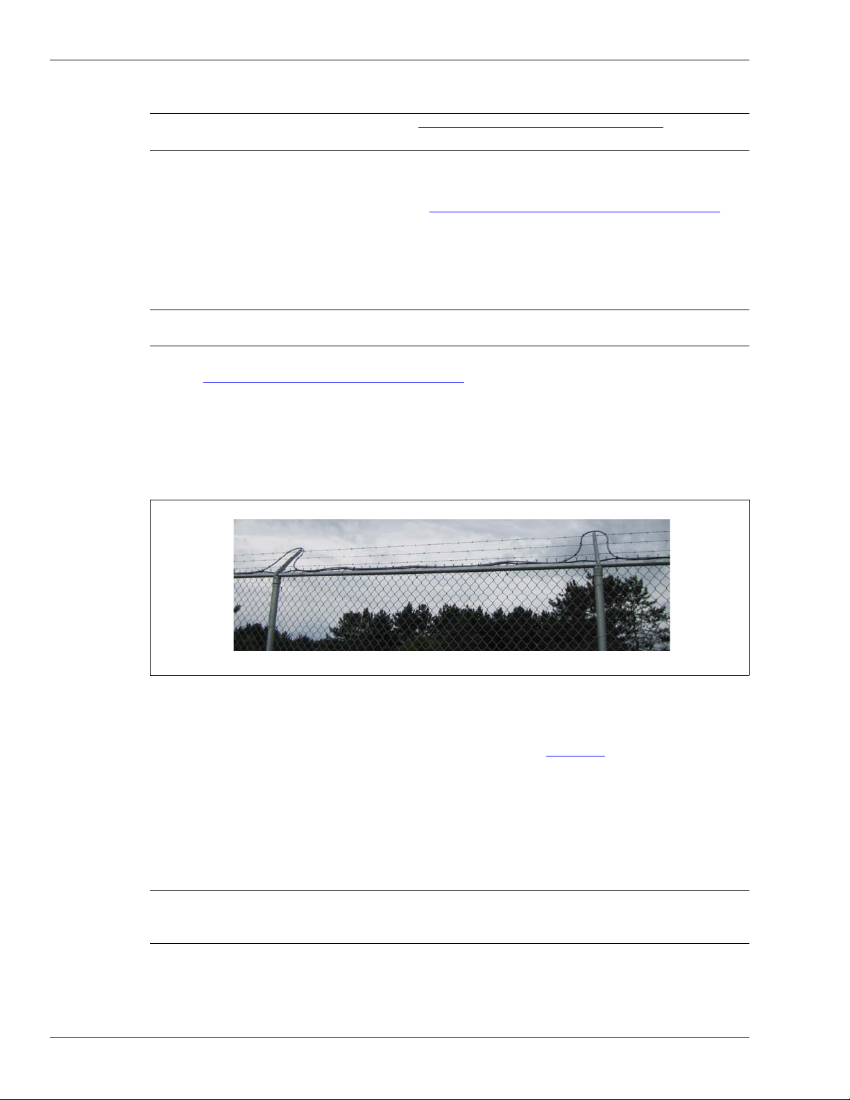
Installing the sensor cable
Armored cable installed beside outriggers
Ensure the minimum bend radius is not violated at the top of each outrigger.
Installing armored FlexZone sensor cable
Note Refer to Installing cable on chain-link
details.
1. Carefully deploy the entire roll of armored sensor cable in a straight line on the ground beside
the installation location.
2. Condition the armored sensor cable (see FlexZone sensor cable conditioning
3. Secure the armored cable to the fence using stainless steel cable ties or wire ties.
Installing cable on barbed wire
Note Senstar recommends the use of armored sensor cable for instances
where the cable is attached to barbed wire or razor ribbon.
Refer to Climb-over deterrent hardware on page 10.
• Take care not to damage the sensor cable on the barbs during installation.
• Attach the sensor cable to the barbed wire using UV-resistant cable ties.
• Attach the cable to the top wire at two points to ensure the minimum bend radius is not
exceeded.
• Attach the cable on both sides of each outrigger and run the cable along the top of the fence.
on page 34 for additional
on page 26).
Figure 51:
Armored cable installation on barbed wire
On razor ribbon
• Attach the sensor wire to the outer perimeter of the coil (see Figure 4: ).
• Use stiffening wires to prevent the concertina from moving.
Splicing armored sensor cable
Armored sensor cable splices use the standard splice kit (P/N G6KT0101) and are protected by an
armored metal shell (G6KT0300).
Note Senstar strongly recommends the use of a conduit stripping tool to
prevent burrs and sharp protrusions at the cut edge of the conduit.
Page 46 FlexZone Product Guide
Use the supplied bushings to protect the cable at the armor strip point.
Page 47

Installing the sensor cable
Fit the protective bushing over the cable and slide it under the armor to protect the sensor cable.
splice location
10 cm
(4 in.)
a. Carefully, remove 6.5 cm (2.6 in.) of the metal jacket. b. Remove 2 cm (0.8 in.) of the black jacket.
c. Separate the strands of the braided shield.
d. Tightly twist the strands of the braided shield into two
separate conductors. Remove the exposed foil shield.
f. Trim the clear tube back to a length of 5 mm (0.2 in.).
Trim the center conductor and twisted shield to a
length of 6 mm (¼ in.) past the end of the clear tube.
e. Trim off the lower shield/conductor
(leave no loose strands).
Figure 52: Using the supplied bushings to protect FlexZone sensor cable
1. Cut the two sections of armored cable so there is a 10 cm (4 in.) overlap at the location of the
splice.
Figure 53: Cutting armored sensor cables for splicing
2. Prepare the two sensor cables for splicing.
Figure 54: Armored cable preparation for splicing
FlexZone Product Guide Page 47
Page 48

Installing the sensor cable
a. Feed each cable through one section of the shell.
b. Insert the center conductor into the lower terminal and
c. Connect the second sensor cable ensuring that shield
the shield into the upper terminal and tighten the
conductor.
meets shield and center conductor meets center
d. Secure the sensor cables to the splice PCB with four
cable ties. Keep the cable ties on the same side, and
at a 45º angle from the flat plane of the CCA.
center conductor
shield
screws (follow the screening on the PCB).
h. Raise the armored shell 15 cm (6 in.) above the cable
run and attach it to the fence horizontally with four cable
ties. For increased security, use stainless steel straps
e. Center the splice between the double cable guide bars
f. Snap the enclosure shut so that the two locking tabs
are latched in the slots, and the enclosure is closed
g. Rotate one half of the armored shell so both screw
and then press the sensor cables firmly into the guide
and locked with gel oozing out of the ends.
bars and the splice CCA into the gel.
or wire ties.
15 cm (6 in.)
drip loop
clamps are pointed toward the ground and fit the two
halves of the shell together with the enclosure
centered inside. Tighten the screw clamps.
3. Make the splice connection.
Armored cable terminations
Armored sensor cable terminations use the standard termination kit (P/N G6KT0201) and are
protected by an armored metal shell (G6KT0300).
Figure 55: Making the splice connection
Note Senstar strongly recommends the use of a conduit stripping tool to
Page 48 FlexZone Product Guide
prevent burrs and sharp protrusions at the cut edge of the conduit.
Use the supplied bushings to protect the cable at the armor strip point.
Page 49

Installing the sensor cable
Fit the protective bushing over the cable and slide it under the armor to protect the sensor cable.
termination location
cut location
53 cm
(21 in.)
a. Carefully, remove 7.5 cm (3 in.) of the metal jacket. b. Remove 2 cm (0.8 in.) of the black jacket.
c. Separate the strands of the braided shield.
d. Tightly twist the strands of the braided shield into two
separate conductors. Remove the exposed foil shield.
f. Trim the clear tube back to a length of 5 mm (0.2 in.).
Trim the center conductor and twisted shield to a
length of 6 mm (¼ in.) past the end of the clear tube.
e. Trim off the lower shield/conductor
(leave no loose strands).
Figure 56: Using the supplied bushings to protect FlexZone sensor cable
1. Cut the armored cable 53 cm past the specified location of the cable termination.
Figure 57: Cutting armored sensor cable for terminations
2. Prepare the sensor cable for termination.
Figure 58: Armored cable preparation for terminations
FlexZone Product Guide Page 49
Page 50

Installing the sensor cable
center conductor
shield
drip loop
a. Feed the cable through 1/2 of the armored shell, and
follow the screening to connect the center conductor
and shield to the terminal block on the CCA.
b. Secure the sensor cable to the CCA with two of the
cable ties. Keep the cable ties on the same side and
at a 45º angle to the flat plane of the CCA.
e. Center the terminator in the enclosure on the side
with double cable guide bars. Press the cable firmly
into the guide bars and the terminator into the gel.
f. Snap the enclosure shut so that the two locking tabs
are latched in the slots, and the enclosure is closed
g. Fit the two halves of the armored shell together with
and locked with gel oozing out of the end.
the enclosure centered inside. Ensure the clamps are
oriented upward, then tighten the clamps.
h. Raise the shell 30 cm (12 in.) above the cable run,
and attach it to the fence horizontally with 4 large
cable ties. For increased security, use stainless steel
30 cm (1 ft.)
straps or wire.
3. Make the termination.
Connecting armored sensor cable to the processor
CAUTION Remove the processor circuit card from the enclosure BEFORE drilling
Page 50 FlexZone Product Guide
1. Remove the two 3/8 in. sensor cable glands from the enclosure’s right side (see Figure 61: ).
2. Carefully drill the 2 holes to fit the 1/2 in. cable glands (22 mm; 7/8 in. bit size).
3. Ensure that all metal shavings from the drilling are removed from the enclosure.
4. Remove the split rubber grommets from inside the 1/2 in. cable glands.
5. Remove 3 in. of the armored jacket.
6. Prepare the sensor cable for connecting to the processor (see Figure 34:
7. Pass the sensor cable through the cable gland into the enclosure then through the nut.
8. Loosely install the 1/2 in. cable glands.
Figure 59: Making the termination
the cable ports to fit the 1/2 in. cable glands (see Removing the
processor assembly on page 90).
).
Page 51

Installing the FlexZone processor
9. Insert the protective grommet under the armor (see Figure 56: ).
10. Remove the terminal block and connect the sensor cable.
11. Plug the sensor cable into the appropriate connector (A Side or B Side) and tighten the nut on
the cable gland to secure the armored cable. There should be about 2.5 cm (1 in.) of armor
inside the enclosure.
12. Use a thin bead of silicone on the inside of the cable gland to seal the fitting.
Installing the FlexZone processor
Do not remove the processor circuit card when installing the enclosure. The processor is shipped
with two gear clamps that are used for securing the enclosure to a post. The hardware required to
mount the enclosure on another type of surface is customer supplied. Figure 62:
mounted FlexZone processor. Figure 60:
includes feature descriptions.
illustrates the FlexZone processor features and Table 1
shows a fence-
Figure 60: FlexZone processor features
FlexZone Product Guide Page 51
Page 52

Installing the FlexZone processor
sensor cable Side B
sensor cable Side A
network communications
relay outputs
12 to 48 VDC
auxiliary inputs/self-test
earth ground
Item Description Item Description
1 Network interface card mounting hardware (X 2) 9 T8 - Form C relay output connections (X4)
Normally Closed, Common, Normally Open
2 Activity LEDs - DOOR OPEN, UCM ACTIVE,
NETWORK POWER FAIL, INTERNAL POWER
FAIL, FPGA ACTIVITY, BOOT FAIL, MEMORY
FAIL, HEARTBEAT, TXA, RXA, FAULT A, TXB,
10 T9 (terminals 1, 2, 3) - A Side sensor cable input
(1 & 3 = shield, 2 = center conductor)
11 T9 (terminals 4, 5, 6) - B Side sensor cable input
(4 & 6 = shield, 5 = center conductor)
RXB, FAULT B (LED ON = condition active)
3 T1 - tamper input 12 T4 - power input (- +) 12 to 48 VDC
4 SD Active LED 13 T7 - Auxiliary inputs (self-test/auxiliary device
inputs) AUX 1 - +, AUX 2 - +
5 SD record button (ON/OFF) 14 Relay activity LEDs (X4) - LED ON = relay active
6 microSD card slot 15 Tamper switch - open = tamper alarm
7 T3 - USB connection to UCM PC 16 T2 - Expansion header for network interface card,
8 UCM activity LEDs (TX, RX)
gate sensor receiver and I/O card
Table 1 Processor features
Cable entry ports
The bottom of the FlexZone enclosure includes five cable entry ports fitted with compression
glands for the sensor cables, power cable, and alarm data cables. The central port includes a
12.7 mm (1/2 in.) cable gland, which fits cables ranging between 4.3 - 11.4 mm (0.17 to 0.45 in.).
The other four ports (two on each side) provide 9.5 mm (3/8 in.) compression glands, which fit
cables ranging between 2.9 - 7.9 mm (0.115 to 0.312 in.). Five weatherproof plugs are included for
instances where not all of the cable entry ports are required. The bottom of the enclosure also
includes an exterior ground lug for the earth ground connection.
If FlexZone armored cable is being connected to the processor, the two sensor cable ports must
be drilled out and fitted with 1/2 in. cable glands (included with armored shell; see Connecting
armored sensor cable to the processor on page 50).
Page 52 FlexZone Product Guide
Figure 61: Cable entry recommendations
Page 53

Installing the FlexZone processor
B-side cable
A-side cable
processor/enclosure
upper gear clamp
Free-standing or fence post mounting the enclosure
• Install the processor near eye-level on the secure side of the perimeter.
• Mount the enclosure with the cable entry ports on the bottom toward the ground.
• Install an approved earth ground at the processor location, if required (see Grounding
considerations on page 21).
• Mounting the enclosure away from the protected fence on the secure side of the perimeter can
help prevent tampering.
• If razor ribbon is installed along the bottom of the fence, mount the processor on the secure
side of the perimeter, away from the fence and razor ribbon.
CAUTION For installations in environments which include hot sunny periods,
Senstar recommends that a sun shield be installed to protect the
enclosure from direct sunlight, or that the enclosure be installed in a
shady area. The maximum operating temperature, as measured
inside the enclosure, is 70º C (158º F).
Figure 62: FlexZone single pass dual zone fence-mounted processor
FlexZone Product Guide Page 53
Page 54

Installing the FlexZone processor
1. Hold the enclosure against the fence at the specified installation location.
2. Feed the end of the gear clamp through an upper flange slot, around the fence post, and back through
the second slot.
3. Insert the end of the gear clamp into the gear mechanism and tighten the screw.
4. Repeat this with the second gear clamp on the lower flange at the bottom of the enclosure.
1. Hold the enclosure against the
2. Drill 4 holes in the mounting surface.
3. Using appropriate hardware, mount
mounting surface, and mark the
positions of the 4 mounting holes.
the enclosure.
use 7mm (¼ in.) hardware
Figure 63: Post-mounting the enclosure (on the fence)
Surface mounting
Figure 64: Surface-mounting the enclosure
Page 54 FlexZone Product Guide
Page 55

Grounding
The FlexZone sensor requires a single ground reference. For standalone processors, PoE
powered processors, and processors that are connected directly to a network power supply,
connect the enclosure ground lug to an approved earth ground. For a connected block of
processors receiving power over the sensor cables, the processor that is connected directly to the
power supply provides the ground reference for the other processors (do not make ground
connections at the other processors). The earth ground connection should be stable and noise
free. An improper or unstable earth ground can induce noise in the FlexZone sensor.
CAUTION Consult the local electrical code for grounding information.
Relay outputs
The FlexZone processor includes four Form C relay outputs available through a removable
terminal block. Each relay has a common connection to either a Normally Open (NO) or Normally
Closed (NC) contact. Each relay has an associated LED, which indicates when the relay is active
(LED ON = relay active). The optional relay output card includes four additional relays.
Installing the FlexZone processor
Do not use the fence structure as an earth ground.
Avoid sharp bends in the ground wire.
Relay contact ratings
The dry contact relays are Form C, latching, rated for 30 V @ 1 A max. In Remote control mode,
you can configure the relays as latching (ON by command, OFF by command), in flash mode (ONOFF-ON-OFF... by command, then OFF by command), or pulse mode (ON for a period, then
OFF). For flash and pulse modes, the relay Active/Inactive times are selectable. In Local control
mode the relays remain active for the event’s duration or for the selectable Hold Time, whichever
is longer.
Auxiliary inputs /Self-test inputs
CAUTION The contact closure inputs to AUX 1 and AUX 2 MUST be
voltage-free.
AUX 1 and AUX 2 are voltage sensing inputs. The processor determines an input’s status via an
internal reference voltage, and the configuration of the contact closures and supervision resistors.
Figure 65:
the inputs activate an internal self test with AUX 1 activating the relays assigned to A Side cable
alarms and AUX 2 activating the relays assigned to B side cable alarms. In Remote control mode
the AUX inputs serve as auxiliary device inputs for reporting their status to the SMS. The optional
dry contact input card includes four additional inputs.
provides wiring diagrams for self-test and auxiliary device inputs. In Local control mode
FlexZone Product Guide Page 55
Page 56

Installing the FlexZone processor
AUX 1 AUX 2
-
+
-
+
NO self-test inputs
Local control mode
dual resistor supervision
NO alarm
dual resistor supervision
NC alarm
Remote control mode
cut and short supervision
cut and short supervision
AUX 1 AUX 2
-
+
-
+
NO auxiliary input
unsupervised
NC auxiliary input
unsupervised
Remote control mode
single resistor supervision
NO alarm
single resistor supervision
NC alarm
Remote control mode
cut supervision
short supervision
Processor wiring connections
Figure 65: Self-test/Auxiliary device input wiring examples
You make FlexZone processor wiring connections on removable terminal blocks. The screw
terminals accept wire sizes from 12 to 24 AWG, with a 6 mm (¼ in.) strip length. Remove the
terminal blocks to make the wiring connections. Reinstall the blocks after the connections are
complete, and verified. Figure 38:
Figure 66:
shows the input/output wiring connections to the FlexZone processor. Figure 67: shows
the input/output wiring connections to the FlexZone option cards. Figure 68:
shows the sensor cable to processor connection procedure.
to Figure 73: show
the Silver Network wiring options.
Note See instruction sheet 00DA1503 for information about installing the
optional relay output card and dry contact input card.
Page 56 FlexZone Product Guide
Page 57

Installing the FlexZone processor
T7
T4
T8
-
+
T9
AUX 1
- +
AUX 2
- +
RELAY 1
NC COM NO
RELAY 2
NC COM NO
RELAY 3
NC COM NO
RELAY 4
NC COM NO
A-SIDE
B-SIDE
POWER
-+-
-+-
T7T4
sensor cable
T8
T9
relay outputs
self-test/auxiliary
inputs
power
input
A-Side
B-Side
- DC GND
+ 12 to 48 VDC
auxiliary/self-test inputs
-
+
AUX input 1
-
+
AUX input 2
relay 1 NC
relay 1 COM
relay 1 NO
relay 2 NC
relay 2 COM
relay 2 NO
relay 4 NO
relay 4 COM
relay 4 NC
relay 3 NO
relay 3 COM
relay 3 NC
+ center conductor
- shield
B SIDE sensor cable
+ center conductor
- shield
A SIDE sensor cable
- shield
- shield
T4 power output for
processors receiving
power over sensor
cables
ROC outputs
DRIC inputs
auxiliary inputs
-
+
OPT input 1
-
+
OPT input 2
OPT 4 NO
OPT 4 COM
OPT 4 NC
-
+
OPT input 3
-
+
OPT input 4
OPT 3 NO
OPT 3 COM
OPT 3 NC
OPT 2 NO
OPT 2 COM
OPT 2 NC
OPT 1 NO
OPT 1 COM
OPT 1 NC
Figure 66: FlexZone processor wiring diagram
Figure 67: FlexZone option card wiring diagram
FlexZone Product Guide Page 57
Page 58

Installing the FlexZone processor
Silver Network wiring connections
Note A network interface card is required to enable Silver Network
Note For groups of FlexZone processors that communicate over the sensor
Silver Network specifications
• Data rate - fixed 57.6 k bps
• Maximum 60 devices spread over up to 4 independent network loops
• Two communication Channels (Side A, Side B)
• Response time - 1 second, or less from alarm source to Network Manager (per loop)
• Network termination - not required
• Transmission media/maximum separation distances between processors:
• EIA-422 copper wire - 1.2 km (0.75 mi.) - 2 pairs per Channel
• Multi-mode fiber optic cable (820 nm) - 2.2 km (1.4 mi.) - 2 fibers per Channel - optical
• Single-mode fiber optic cable (1310 nm) - 10 km (6.2 mi.) - 2 fibers per Channel - optical
• Ethernet - Category 5 cable, 100 m between PoE switch and processor location
communications between a FlexZone processor and the Silver Network
manager.
cables, only the processor that is connected directly to the Silver
Network requires an NIC.
power budget 8 dB
power budget 8 dB
Note Use low capacitance shielded twisted pair data cable for EIA-422,
62.5/125 multi-mode fiber optic cable,
9/125 single-mode fiber optic cable, and
Category 5 Ethernet cable.
The maximum separation distances require high quality transmission
media and sound installation practices.
CAUTION Both the FlexZone processor and the network interface cards contain
static sensitive components. Follow proper ESD handling procedures
when handling the cards.
Ensure the expansion header on the NIC is properly lined up and fully
seated in T2 on the processor.
Page 58 FlexZone Product Guide
Page 59

Installing the FlexZone processor
expansion header T1
use single point grounding
(plugs into T2 on processor)
mounting hardware (X 2)
A-side comms
B-side comms
(connect one end of cable
(on solder side)
the other end and leave
it disconnected)
shield to ground, trim back
Figure 68: Silver Network EIA-422 wiring connections
FlexZone Product Guide Page 59
Page 60

Installing the FlexZone processor
expansion header T1
T4 processor power input
(plugs into T2 on processor)
mounting hardware (X 2)
PoE NIC DC output (12 VDC)
Ethernet network connection
(on solder side)
The PoE NIC typically receives power over its
Ethernet connection. It provides power to the
processor through T4, the processor power input.
The processor then supplies power to the NIC
through the expansion header.
If the PoE NIC is not receiving power over its
Ethernet connection, the processor must have
another source of DC power connected to T4.
Connect the PoE NIC ground strap to a ground lug
on the enclosure.
Connect the enclosure ground lug to a nearby
approved earth ground.
EIA-422
Fiber Optic
* Use single point grounding. Connect one end of the cable shield to ground, trim
back the other end and leave it disconnected.
Figure 69: Silver Network Ethernet wiring connections
Silver Network data path connections
In the standard Silver Network setup, a point to point loop configuration is used for network
communications. Figure 70:
EIA-422 and fiber optic communication options. Figure 71:
Network and Figure 72:
communications use a star configuration. Figure 73:
(Star configuration) and Figure 74:
processors are connected to the NMS via Ethernet NICs and a PoE switch, and then communicate
with other processors via the sensor cables.
shows the processor to processor network connections for the
shows a fiber optic based Silver Network. Silver Network’s using Ethernet
shows a Silver Loop + Ethernet configuration in which two
Figure 70: Silver Network data connections (loop configurations)
illustrates an EIA-422 based Silver
illustrates an Ethernet based Silver Network
Page 60 FlexZone Product Guide
Page 61

Installing the FlexZone processor
11
223344
55
R
X
B
+
R
X
B
G
N
D
T
X
B
+
T
X
B
-
R
X
A
+
R
X
A-
G
N
D
T
X
A+
T
X
A-
11
223344
55
12345 12345
1
1
22334
4
5
5
123451234
5
12345 12345
R
X
B
+
R
X
B
G
N
D
T
X
B
+
T
X
B
-
R
X
A+
R
X
A
G
N
D
T
X
A+
T
X
A-
R
X
B
+
R
X
B
G
N
D
T
X
B
+
T
X
B
-
R
X
A+
R
X
A-
G
N
D
T
X
A
+
T
X
A-
R
X
A+
R
X
A-
G
N
D
T
X
A+
T
X
A-
12345
RXB+RXB-GND
TXB+TXB
-
12345
maximum 60 processors
max. distance between processors = 1.2 km (3/4 mile)
first processor second processor last processor
shield
shield
shield
shield
shield
shield
NOTE:
Network Interface Unit
lightning
arrestors
lightning
arrestors
to Network Manager
Use single point grounding. Connect one end of the cable shield to ground, trim back the other end and leave
it disconnected.
TXB RXBTXA RXA
TXB
RXB
TXA
RXA
TXB
RXB
TXA
RXA
TXB
RXB
TXA
RXA
maximum 60 processors
first processor
second processor
last processor
Network Interface Unit
to Network Manager
maximum distance between processors
multi-mode fiber optic = 2.2 km (1.4 miles)
single-mode fiber optic = 10 km (6.2 miles)
Figure 71: Silver Network EIA-422 wiring diagram
Figure 72: Silver Network fiber optic wiring diagram
FlexZone Product Guide Page 61
Page 62

Installing the FlexZone processor
maximum 60 processors
first processor
second processor
last processor
Network
maximum distance
third processor
fourth processor
fifth processor
Manager
computer
security
management
system
computer
between processor
and PoE switch
100 m (328 ft.)
Category 5 Ethernet cable
class 3
PoE
switch
maximum 60 processors
first processor
second processor
last processor
Network
maximum distance
third processor
fourth processor
fifth processor
Manager
computer
SMS PC
between processor
and PoE switch
100 m (328 ft.)
Category 5 Ethernet cable
class 3
PoE
switch
FlexZone sensor cable
Ethernet NIC
*
processors that are not connected to PoE switch require a DC power source
UCM
settings
connection
Ethernet NIC
Figure 73: Silver Network Ethernet wiring diagram
Figure 74: Silver Network Ethernet + Loop wiring diagram
Page 62 FlexZone Product Guide
Page 63

Power connections
maximum 5 processors
first
second
Network
third
Manager
computer
processor
processor
48 VDC
power supply
NIU
NIC
UPS
AC
per 48 VDC power supply
processor
fourth
processor
fifth
processor
splice
splice
splice
splice
terminators
WARNING! DO NOT bring AC mains power into the FlexZone enclosure. If a local
Note When a central low voltage power supply is being used for primary
Power over sensor cables
Power can be supplied to a group of up to five FlexZone sensors by connecting the central
processor to a 48 VDC power supply, and then connecting its two sensor cables (one on each
side) to one of the sensor cables of the two adjacent processors through splice kits. The second
sensor cable of each adjacent processor is then connected to one of the sensor cables of the two
outside processors. This configuration also enables data communication over the sensor cables.
Setting up power distribution and data communication over the sensor cables is done via the
UCM. To enable alarm data communication over the sensor cables, at least one processor
requires a data link connection to the Silver Network through a network interface card. Figure 75:
illustrates the power and data over the sensor cables concept.
Installing the FlexZone processor
power supply is being used, it must be installed in its own weatherproof
enclosure. Consult the local electrical code for information about the
connection of AC mains to your power supply.
power, it should be powered from an uninterruptible power source.
Local power supply
Figure 75: Silver Network power and data over sensor cables
It is possible to use a local DC power supply when a source of AC power is readily available near
FlexZone Product Guide Page 63
the processor. The DC power supply must be installed in its own weatherproof enclosure. The
local supply can be mounted on the same post as the processor to keep the wire runs to a
minimum. Each processor being powered by a local DC power supply requires an earth ground
connection.
Page 64

Installing the FlexZone processor
Power over Ethernet
For power over Ethernet, a class 3 PoE switch is required. In this configuration, minimum Category
5 cable is required and the maximum distance between the FlexZone processor and the PoE
switch is 100 m (328 ft.). Each processor receiving PoE requires an earth ground connection.
CAUTION The PoE NIC is intended to supply power only to the processor on
Auxiliary device power output
Processors that are receiving power via the sensor cables can be setup (via the UCM) to supply
power (2 W) to an auxiliary device. In this case the power connector T4 is used to make the
auxiliary device power connection. The output voltage at T4 is equal to the input voltage over the
sensor cables. The auxiliary device can communicate its alarm status through the FlexZone
processor’s Aux inputs (in Remote control mode).
Senstar’s UltraWave microwave sensor can receive power from a FlexZone processor, as well as
communicate alarm status via the Silver Network or through the FlexZone processor’s Aux inputs.
The recommended method is via the Silver Network which requires network interface cards on
both the FlexZone processor and the UltraWave receiver. Figure 76:
diagrams for the UltraWave microwave sensor in both Local and Remote control modes. Contact
Senstar Customer Service for additional details.
which it is mounted. Do not attempt to power an auxiliary device with
the PoE NIC.
illustrates connection
Backup power
Senstar recommends that the FlexZone sensor system be powered from an uninterruptible power
supply (UPS). Connect AC mains to the UPS and the UPS to the DC power source. In this way, if
AC power is interrupted, the FlexZone sensor system can operate on battery power while AC
power is being restored.
Page 64 FlexZone Product Guide
Page 65

UltraWave Remote control mode Silver Network wiring
UltraWave transmitter
UltraWave receiver
FlexZone processor using power & data via sensor cables
supplying power and data connection to UltraWave sensor
network connection setting
UltraWave Local control mode relay output alarm wiring
O/P 1 Alarm
O/P 2 sup’vn
(N.O. alarm contacts)
FlexZone processor using power & data via sensor cables
supplying power and auxiliary input data connection to
UltraWave sensor
UltraWave transmitter
UltraWave receiver
*
Use single point grounding. Connect one end of
the cable shield to ground. Trim back the other
end and leave it disconnected.
Installing the FlexZone processor
Figure 76: UltraWave connection diagrams (Silver Network & Relay)
FlexZone Product Guide Page 65
Page 66

Installing the FlexZone processor
Page 66 FlexZone Product Guide
Page 67

3 Calibration & setup
USB direct connection
TCP/IP connection via Network Manager
in the Network Type: field select the network to
which you are connecting (Silver for FlexZone)
in the Device Type: field select the device (FlexZone -4 or -60)
the address of the connected processor is displayed
select the connection type (i.e., USB)
select the arrow to display the connected USB device
select the connect button to establish the connection
in the Network Type: field select the network to which you
are connecting (Silver for FlexZone)
to connect via the Silver Network Manager, use the Browse
button to locate the processor address OR use the Address
field to specify the processor address (Browse requires a
previously specified IP address and Network Manager ID)
select the connection type (i.e., TCP/IP)
enter the IP address of the Network Manager PC
(if the NM and UCM are located on the same PC,
enter 127.0.0.1 as the IP Address)
specify the ID number assigned to the Network Manager
select the connect button to establish the connection
in the Device Type: field select the device (FlexZone -4 or -60)
The Universal Configuration Module
Note Consult the online help for detailed information on UCM operation.
The Universal Configuration Module (UCM) is a Windows based software application, which
serves as the calibration, setup and maintenance tool for the FlexZone sensor system. The UCM
communicates with the FlexZone processor locally through a USB connection, or remotely via the
Silver Network Manager. When you start the UCM, a window displays that enables you to specify
the device to which you are connecting.
FlexZone Product Guide Page 67
Tip Save UCM files with a meaningful name, which includes the time and
date. The files can then be reopened at a later time (Work Offline).
Figure 77: Connecting the UCM
Page 68

FlexZone setup and calibration requires:
1. Setting the initial configuration parameters as required (Cable Supervision, Network Address,
Network configuration, processor Synchronization, single or double cable pass).
2. Setting up the power distribution and alarm data communication schemes.
3. Conducting a Sensitivity Profile for each sensor cable (A-Side, B-side).
4. Adjusting the cables’ threshold settings and detection parameters (Event Window, Event
Count, Alarm Window).
5. Defining and setting up the cable segments and alarm zone boundaries.
6. Setting up the Auxiliary input/output control.
7. Testing the installation.
FlexZone definitions
• meter - The meter is the basic unit of measure for FlexZone sensor cable. The meter is used
to define cable segments. The sensitivity profile records the cable sensitivity for each meter of
detecting sensor cable.
• cable segment - A cable segment is made up of a contiguous group of meters, and is used for
display and control purposes. Cable segments are software-defined during setup. The cable
segment is the smallest unit that is defined by the end-user. Each sensor cable can be divided
into up to 50 cable segments. Cable segments are used to create alarm zones, and therefore,
must begin and end where alarm zone boundaries are required. A single cable segment, or
multiple cable segments, can be assigned to one zone. A cable segment can have one of the
four onboard relays associated with it for alarm reporting. In addition to the event Threshold
that is set for the full length of detecting cable, an independent Threshold adjustment can be
made for each cable segment. Cable segments can also be defined as inactive, whereby
detecting cable will not report valid targets (by assigning a cable segment to Zone 0).
• alarm zone - An alarm zone is made up of one or more cable segments, and is used for the
control and annunciation of sensor alarms (access/secure, graphic map display with precise
target location). There can be up to 60 alarm zones per FlexZone-60 processor (over two
sensor cables) and up to four for a FlexZone-4 processor. Alarm zones are defined in software
to match the site-specific zone layout details (e.g., CCTV coverage, fence sections, gates,
buildings, etc.). Any grouping of segments can be assigned to an alarm zone. The cable
segments do not have to be contiguous, and can come from both sensor cables on one
processor (not two processors). There can be a zone within another zone, and a zone can
bridge inactive cable segments. Zone 0 does not report alarms, and is used for cable
bypasses, and to set detecting cable to inactive (non-detecting). Zone 0 does not count in the
60, or 4 zone total.
Understanding FlexZone alarm detection
The FlexZone processor constantly evaluates the input signals from the sensor cables to
discriminate between intrusion events and environmental activity. The characteristic response of a
cut event is a sharp spike with a fast rising and fast falling edge. For a climb event, the response
includes the fast rising edge caused by the initial contact with the fence, which is followed by a
series of peaks and valleys resulting from the continued presence and changing stresses on the
fence. Environmental activity is generally of longer duration, lower magnitude, and has more
gradual increases and decreases. The FlexZone processor analyzes the received signals from the
sensor cables and records separate Events independently. As a result, the processor can record
and report multiple disturbances over the length of the sensor cable.
Note FlexZone’s minimum target resolution for perfectly synchronized
disturbances is 24 m (79 ft.).
Page 68 FlexZone Product Guide
Page 69

The Threshold is the received signal strength at which an Event is added to the Event Count. It is
measured in dB and can be set globally for the full length of detecting cable. An independent
Threshold can also be set for each defined cable segment.
• When the rising edge of the received signal from the sensor cable exceeds the Threshold, the
Event Count is incremented by one.
• The next Event will not be recorded until the period specified by the Event Window has
expired.
• Once the Event Window time has expired, when the rising edge of the received signal from the
sensor cable exceeds the Threshold, the Event Count is incremented by one.
• If the received signal remains above the Threshold for the period specified by the Event
Window (i.e., a climbing intrusion) the Event Count is incremented by one.
• Each time the Event Count is incremented, the Alarm Window time is reset to zero.
• When the value specified as the Event Count is reached within the Alarm Window time, a
sensor alarm is triggered, and the Event Count is reset to zero.
• If the Alarm Window Time expires the Event Count is reset to zero without triggering an alarm.
Intruder detection
The FlexZone sensor guards against three intrusion scenarios:
• An intruder attempts to cut through the fence fabric.
• An intruder attempts to climb over the fence.
• An intruder attempts to crawl under the fence by lifting the fence fabric.
An intrusion alarm resets automatically when the event is over or when the Alarm Hold Time
lapses. The Alarm Hold Time is a factory setting which is used to prevent subsequent alarms from
being declared at the same location. The Alarm Hold Time is three seconds, and cannot be
adjusted. Once the processor declares an alarm at a location, another alarm will not be triggered
at that location for three seconds.
Intrusion detection
Cutting the fence fabric produces a high amplitude signal that exceeds the Threshold. The first
time the detection signal exceeds the Threshold, the Event Count is incremented, and the Alarm
Window time count begins. The Event Window time setting must lapse before another Event will
be counted. Each time the Event Count is incremented the Alarm Window time count is reset to
zero. When the Event Count reaches the specified value within the Alarm Window time setting, the
system generates a sensor alarm. If a subsequent Event is not recorded before the Alarm Window
time runs out, the Event Count and the Alarm Window reset to zero.
When an intruder attempts to climb over the fence, or lift the fence fabric, a large number of energy
pulses rapidly occur causing the received signal to exceed the Threshold. When the signal first
exceeds the Threshold, the Event Count is incremented by one, and the Alarm Window time count
begins. Typically, during a climb or lift type intrusion, the received signal remains above the
Threshold as a result of the continued flexing and stressing of the fence fabric. The initial contact
with the fence activates the Event Window time counter. Each time the Event Window time is
reached, and the received signal strength remains above the Threshold, the Event Count is
incremented by one. Each time the Event Count is incremented the Alarm Window time count is
reset to zero. When the Event Count reaches the specified number within the Alarm Window time
period, the processor generates a sensor alarm at that location.
FlexZone Product Guide Page 69
Page 70

Initial processor setup
Initial processor setup
Senstar recommends that the initial setup be done at the processor location using a direct USB
connection to the UCM.
Note An enclosure tamper condition must exist to enable UCM
communication via a USB connection.
Note The processor’s Address and Network Configuration settings can be
adjusted only through a direct USB connection.
Connecting the UCM via USB
1. Open the enclosure cover and connect the UCM computer to the processor via USB (T3).
2. Start the UCM software (the UCM Connect dialog displays see Figure 77:
3. Specify the connection details:
(e.g., Network Type: = Silver Network; Device Type = FlexZone-60 or FlexZone-4; Address =
1 {default address}; select USB radio button; USB Device = FlexZone)
4. Select Connect to establish a connection to the processor.
The FlexZone Status window opens.
).
Setting the processor address
Note Processors that do not use Silver Network communications can use the
default address of 1.
1. In the Program field select the Address button.
The change Device Address dialog displays.
2. In the Change Device Address dialog, specify the New Address for the connected processor.
3. Select the Program button.
The new address takes effect when communications are reestablished.
Network configuration
For FlexZone processors that use Silver Network alarm data communications, you must define the
network Protocol and Connection scheme under the Network Cfig tab. The network configuration
can be adjusted only by using a direct USB connection between the UCM computer and the
processor. For Silver Network based processors, there are two selectable Protocols based on the
network configuration:
• The Silver Star Protocol uses an IP backbone and a direct Ethernet connection to each
processor. This configuration is most commonly used when the sensor network is distributed
over a large area and consists of isolated blocks of sensors with only a few processors in each
block.
• The Silver Loop Protocol is designed to encircle a perimeter using a ring topology to provide
communication redundancy. The Silver Loop Protocol can use EIA-422 wiring, fiber optic
cables, or sensor cables to connect the distributed processors; and the Silver Loop can use a
Network Interface Unit or Ethernet NIC(s) to connect to the Silver Network Manager.
Page 70 FlexZone Product Guide
Page 71

1. Specify the network Protocol - Silver (Loop) or Silver (Star).
422/FO(A)<>Coax(B)
AB
Coax + 422/FO
A
B
Coax(A)<>422/FO(B)
ABAB
Coax422/FO
AB
Coax(A)<>Ethernet
A
B
Ethernet<>Coax(B)
A
B
synchronization signal (out A in B)
network communication data flow
EOL resistor supervision
Cable pair/loop supervision
(enables power over sensor cables function)
specify the length of cable between the 2 processors
2. Specify the Connection scheme for network communications (see Figure 78:
3. For the Silver Star configuration, and for Silver Loop configurations that use combined
Ethernet and Coax communications specify the IP address, the subnet mask and the gateway
IP address for each processor (if applicable).
4. Save and download the configuration changes to the processor.
Figure 78: FlexZone network connections
Sensor cable supervision
You must specify the sensor cable supervision method for each connected FlexZone sensor
cable. Several other functions depend on this setting including power and data distribution over
the sensor cables as well as auxiliary power output.
1. Select the Side A Cfig tab.
2. In the Cable Side Configuration field, select the Cable Supervision Mode for the Side A cable:
Initial processor setup
).
FlexZone Product Guide Page 71
Figure 79: FlexZone sensor cable supervision
3. Repeat for the Side B cable.
4. Save and download the configuration changes to the processor.
Adjacent Processor (m) setting
If the selected cable side is connected to another processor via the sensor cables, you must
specify the total length of sensor cable between the 2 processors:
1. Select the Side A Cfig tab.
2. Select the total length of the 2 connected sensor cables from the Adjacent Processor (m) drop
down menu:
Figure 80: FlexZone sensor cable supervision
3. Repeat for the Side B cable (if necessary).
4. Save and download the configuration changes to the processor.
Page 72

Initial processor setup
select cable pair supervision to enable
green indicator indicates power distributed
green indicator indicates power distributed
over B side sensor cable
power distribution over the sensor cable
green indicator indicates auxiliary power output
over A side sensor cable
available via T4 (2 W)
select the test check-box to verify that
the specified function is operational
select the Enable checkbox to
select the DC Power Output checkbox to
distribute power via the selected cable side
select the Aux DC Power Output checkbox to
supply 2 W of power to an auxiliary device via T4
NOTE: The Aux Power Output voltage is equal to the voltage received over the sensor cables.
Power over the sensor cables and auxiliary DC power output are available only when
the processor’s input voltage is 38 VDC or greater.
turn ON the cable side
specify the cable length to the connected processor
uncheck the Accept Sync Signal checkbox only
if this processor will be the Sync Master
select the Double Pass checkbox if this processor
will monitor a double pass of sensor cable
specify the type of fence (Rigid or Flexible)
Power over sensor cables
If this processor receives power from a 48 VDC power supply and will distribute power over the
sensor cables to other processors, you must setup the power distribution scheme via the UCM. If
this processor receives power over the sensor cables, and will provide power to an auxiliary device
via the power connector (T4) you must setup the auxiliary power output function via the Aux Cfig
tab on the UCM.
The UCM Diagnostics Status field includes three indicators along with voltage and current
readings for Cable A, Cable B and Input/Aux (Auxiliary power output - Volt readings only). There
are also three test checkboxes that are used to test and verify the selected power distribution
function.
Use the test checkboxes on the Status screen to temporarily change the power distribution
function (Cable A power distribution, Cable B power distribution, Auxiliary power output via T4).
Changes made go into effect immediately and revert to the original configuration when the UCM is
disconnected.
Note The Cable Supervision Mode must be set to cable pair supervision
before the test function can be used.
Page 72 FlexZone Product Guide
Figure 81: FlexZone power over sensor cable settings
1. On the UCM Status tab in the Diagnostic Status field, select the Cable A checkbox to verify the
power distribution function, if this processor will distribute power over the A side cable.
2. Select the Cable B checkbox to verify the power distribution function, if this processor will
distribute power over the B side cable.
Page 73

3. Select the Input/Aux checkbox to verify the auxiliary DC power output function, if this
processor will supply power to an auxiliary device via T4.
Note The test functions are temporary settings and the processor will revert
to the Side A, Side B and Aux configuration settings when reset.
Once the functions are tested and verified on the UCM Status tab:
1. For power distribution via the A Side cable, on the Side A Cfig tab, select DC Power Output
and Cable pair/loop supervision.
2. For power distribution via the B Side cable, on the Side B Cfig tab, select DC Power Output
and Cable pair/loop supervision.
3. If this processor will provide power to an auxiliary device via T4, select the Aux DC Power
Output checkbox on the Aux Cfig tab.
4. Save and download the configuration changes to the processor.
Processor synchronization
For fully closed perimeters with 2 or 3 processors uncheck the Accept Sync Signal checkbox on
one of the processors (see Figure 81:
Initial processor setup
).
For open ended perimeters, leave the Accept Sync Signal checkbox checked for all of the
connected processors (default setting).
Audio “listen-in” function
The Audio listen-in function of the FlexZone processor provides a digital audio representation of
the signals received from the FlexZone sensor zones. The FlexZone Audio Tool (NMS Audio.exe)
is a Windows application that produces an audio output based on the fence disturbance signals
picked up by FlexZone sensor cable. The NMS Audio MUX node is used to define the FlexZone
sensor zones available for audio monitoring. The Audio Tool can be used to listen to one zone, or
to multiple zones, through the default audio device of the computer on which it runs. The Audio
Tool can be run on any computer that has a network connection to the target NMS. The Audio Tool
is available on CD as an add-on to the NMS (p/n 00SW0250). FlexZone Audio uses the existing
Silver Network media. No additional cables are required.
Note Refer to the NMS Front Panel and Audio Tool online help files for
additional details on FlexZone Audio setup.
Using the Audio listen-in function via the UCM
The UCM enables the Audio listen-in function through a local USB connection or remotely via the
Network Manager. With a UCM connection you can listen to one zone, or one sensor cable, or
both sensor cables through the computer’s audio device. To use, or test, FlexZone’s Audio listenin function via the UCM make a connection between the UCM and the FlexZone processor.
1. On the Status tab in the Audio field specify what will be monitored (Zone, Cable A, Cable B
Cable A & B).
2. Select the Speaker button to enable the Audio listen-in function.
3. Set the Squelch to prevent low level background noise from producing an audio output.
FlexZone Product Guide Page 73
Page 74

Initial processor setup
specify the Zone, or sensor cable side(s) to Monitor
select the Speaker button
to enable or disable the listen-in function
use the Squelch spin control to prevent low level
background noise (clutter) from producing audio
use the Limit spin control to limit the audio response
to high level disturbance signals
if Zone is the Monitor selection, use the spin control
to select the Zone number
Security
Management
System
FlexZone
Audio Tool
Silver Network Manager Service
Network Interface Unit
FlexZone
processor
FlexZone
processor
FlexZone
processor
4. Set the Limit to cut off high level signals (the high level signals will have already produced an
audio output upon exceeding the Squelch setting).
5. If Zone is selected for monitoring, use the Zone spin control to specify the Zone number.
Figure 82: FlexZone Audio output via the UCM
Using the Audio listen-in function via the FlexZone Audio Tool
To setup and enable the Audio listen-in function for a security management system or a remote
PC requires the FlexZone Audio Tool (see Figure 83:
• The FlexZone processors must be setup and configured as Silver Network based devices and
must be communicating with the Silver Network Manager Service.
Make a list of the FlexZone sensor zones that require the listen-in function and include a brief
description (e.g., Processor 1, Zone 3, East fence).
• The Silver Network Manager Service must be setup and configured and must have the
FlexZone processors and Audio MUX node defined through the Front Panel. The NMS Audio
MUX node is used to define the FlexZone sensor zones to support the audio listen-in
capability (100 audio channels available).
• The FlexZone Audio Tool, a software add-on to the Network Manager Service, must be setup
and configured to enable the audio output. The Audio Tool must be communicating with the
Silver Network Manager Service.
).
Note Only one Audio Tool can connect to an Audio MUX node at a time.
The order that the Audio channels are defined in the Network Manager
Front Panel is the order in which they are displayed by the Audio Tool.
Page 74 FlexZone Product Guide
Figure 83: FlexZone Audio output via the Audio Tool
Page 75

Processor calibration
When calibrating the FlexZone processor for the first time, begin with the detection parameters in
the default settings.
The Sensitivity Profile
A Sensitivity Profile should be recorded for each FlexZone sensor cable (Side A cable, Side B
cable). The Sensitivity Profile records the sensor’s measured response to a fence disturbance
along the full length of the detecting cable. The profile will verify the sensor cable’s performance
and can identify problems on the fence. The Sensitivity Profile also serves as the baseline for
setting the Threshold at which Events are recorded and added to the Event Count.
Recording the Sensitivity Profile
Note For a double pass installation drag the screwdriver along the fence
approximately halfway between the upper and lower cable passes. See
the UCM online help for additional details.
Processor calibration
The recommended method for creating the Sensitivity Profile is to drag a screwdriver or similar
instrument along the fence fabric 15 to 30 cm (6 to 12 in.) above, or below, the sensor cable.
Beginning at the start point of the detecting cable, place the screwdriver against the fence fabric
and apply consistent pressure as you walk along the side of the fence. Keep the pressure steady
and maintain a uniform pace as you drag the screwdriver along the fence fabric. When you reach
the first fence post, lift the screwdriver over the post. Continue dragging the screwdriver along the
fence fabric maintaining a consistent distance from the sensor cable until you reach the end of the
detecting cable. Keep the pressure of the screwdriver and your walking pace as consistent as
possible. Repeat this process from the end of the detecting cable back to the start point.
Note If a sensitivity profile indicates a drop of 20 dB within a 10 m length of
cable, it indicates that there is likely a problem with either the cable at
that location (e.g., improper conditioning, kinked, damaged cable) or
with the fence condition at that location (e.g., loose, sagging, stretched).
Tip Senstar recommends that you save a UCM file that includes the
recorded sensitivity profile. This can be useful for future maintenance
and troubleshooting activities.
FlexZone Product Guide Page 75
Page 76

Processor calibration
raw sensitivity profile data
(gray line)
use the controls in the Profile field
select the Record button to start
recording the profile
(becomes Stop button while recording)
to setup the profile being recorded
The Sensitivity Profile procedure is best conducted with two people, one to cause the fence
disturbance and one to operate and monitor the UCM Profile window.
1. Establish a connection between the UCM and the processor.
2. Select the Side A Cfig tab and then select the Profile button.
3. Verify that the All radio button is selected, and then select the Record button to begin
recording the Sensitivity Profile for Side A.
4. At the start point of detecting cable for Side A, begin dragging the screwdriver along the fence
fabric.
5. Maintain consistent pressure and a steady pace and continue dragging the screwdriver along
the fence fabric near the sensor cable until reaching the end of the detecting cable.
6. Repeat this process, dragging the screwdriver from the end point back to the start point.
7. Select the Stop button to stop recording the Sensitivity Profile.
8. Review the Sensitivity Profile to verify that it was successful. Look for a reasonably flat
response that is somewhat lower near the end of the cable than at the beginning (typically a
20 dB drop over a 300 m cable).
Note You can use the Disable function on the Profile window to trim out the
9. Once you are satisfied with the profile, select the Update button to load the Sensitivity Profile
data. If the recorded Sensitivity Profile is not acceptable, select the Undo button and repeat
the profile procedure.
10. Close the Profile window and download the Sensitivity Profile data to the processor.
11. Repeat this procedure for the Side B sensor cable.
Figure 84: Sensitivity Profile
areas with low signal responses at the beginning and end of the
Sensitivity Profile by specifying the range of Meters and selecting the
Disable button.
Page 76 FlexZone Product Guide
Page 77

Detection parameter setup
Event Window setting
Event Count setting
Alarm Window setting
cable Threshold adjustment arrows
recorded Profile (gray line)
Threshold set to 6 dB below profile (red line)
(period that must lapse before a subsequent
Event is counted)
(number of Events that will cause an alarm)
(period in which a subsequent
Event must occur)
The FlexZone detection parameters are setup independently for each cable side. The Side A Cfig
tab settings apply only to the A side sensor cable and the Side B Cfig tab settings apply only to the
B side sensor cable. FlexZone detection parameters include the cable Threshold, the segment
Threshold, the Event Window, the Event Count and the Alarm Window.
Each FlexZone installation includes many site-specific factors, therefore, each FlexZone
processor must be calibrated to meet the site’s detection requirements. You can adjust the cable
Threshold to increase or decrease the detection sensitivity for the full length of detecting cable.
You can adjust the segment Threshold to increase or decrease the detection sensitivity of a
defined cable segment. You can specify the number of Events required to trigger an alarm, and
the period of time that must lapse before a subsequent Event will be recorded at the same
location. You can also specify the period of time in which a subsequent Event must occur.
Processor calibration
Defining a zone
When the profile is completed and updated, the sensor cable will have a single segment which is
FlexZone Product Guide Page 77
not assigned to a zone (Zone 0). Begin by assigning Segment 1 to Zone 1.
Setting the cable Threshold
Before recording a sensor plot to locate and identify the cable segments and zones, set the full
length cable Threshold. Use the arrows beside the Cable Settings chart to lower, or raise the
Threshold. A good starting point is to set the Threshold at 6 dB below the recorded Profile.
Note You can also adjust the Threshold by left-clicking in the window and
Figure 85: Detection parameter setup
using the up and down arrows on the keyboard, or the mouse wheel.
Page 78

Processor calibration
Defining the cable segments and alarm zones
The cable Threshold represents the received signal level at which the Event Count is incremented.
The cable Threshold is set with respect to the recorded Sensitivity Profile This provides a uniform
Event Threshold for each meter of detecting cable.
Once the Sensitivity Profile is completed and downloaded to the processor, you can set the cable
Threshold.
1. Establish a UCM connection to the processor and select the Side A Config tab.
2. Use the cable Threshold adjustment arrows to set the Threshold for the full length of detecting
cable.
3. Save the UCM file and download the configuration data to the processor.
4. Repeat this procedure for the Side B cable.
Each FlexZone sensor cable can be divided into as many as 50 cable segments (100 per
processor). The defined cable segments can then be assigned to as many as 60 distinct alarm
zones per FlexZone-60 processor, or 4 zones per FlexZone-4 processor. In addition, there is Zone
0, which does not report alarms, and does not count against the total number of zones. You use
the UCM software to divide the sensor cable into cable segments, according to your site-specific
requirements for alarm zone layouts. You can also adjust the Threshold independently for each
cable segment to increase or decrease the sensitivity in that segment.
Locating the cable segment boundaries
Note Senstar strongly recommends marking the zone boundaries on the
fence to ensure that the zone boundary tap tests are done at the correct
locations. Pieces of tape or string tied to the fence can identify boundary
locations for the tap tester.
Tip You can accurately locate cable segment boundaries by tapping the
fence at the boundary location.
1. Establish a UCM connection to the processor and select the Side A Config tab.
2. Select File > Magnitude plot and set the FlexZone response plot to Display Format Magnitude
vs Location, Absolute and Peak Capture.
3. Select the Record button to start the plot.
4. Have the tester tap the fence at the boundary location (or feature) with the blade of a
screwdriver (or similar object).
5. Repeat the fence tap at the same location, using the same amount of force, 5 times waiting 3
seconds between each tap. Move along the cable and continue tapping the fence to mark all
of the required cable segment boundaries. (e.g., start point of detecting cable, end of detecting
cable, site specific alarm zones - beginning and end of each zone).
6. Refer to the response plot to define the cable segments and alarm zones on the Segment
Settings window.
7. Repeat this procedure for the Side B cable.
Defining the cable segment boundaries
The following procedures are performed in the Cable Settings field of the Side A or B Cfig tab.
Page 78 FlexZone Product Guide
Page 79

Processor calibration
132
magnification buttons
use the Delete button to merge the selected
segment with the preceding segment
no Zone label for segments assigned to Zone 0
the assigned Zone label is centered at the top
of the segment
Refer to the magnitude response plot created during the locating the cable segment boundaries
tap test procedure to calculate and note the average location of each segment boundary.
Note To precisely locate the segment boundaries, you can use the UCM’s
Range (m) spin control to enter the meter where a segment begins. You
can adjust only the start point of each segment using the Range control.
The end of a segment is determined by the beginning of the next
segment, or the end of the detecting cable.
Defining sensor cable as non-detecting (setting the start point of detecting cable)
Note Any sensor cable that is located before the designated start point and
after the designated end point of detecting cable must be set as nondetecting. Any cable bypasses must also be set as non-detecting.
1. Below the Segment Setting window on the Side A Cfig tab, select the Split button.
The Profile graph is divided into 2 sections, the white section is the currently selected
Segment.
2. Use the Range (m) spin control to enter the meter at which detection will begin (the beginning
of the second segment).
3. Use the Segment spin control to select segment 1 (or left-click on the gray portion of the
window).
4. Use the spin controls to assign Segment 1 to Zone 0.
5. Save the UCM file and download the configuration data to the processor.
Defining the detecting cable segments
Once you have defined the lead-in cable section as Zone 0 you can define the detecting cable
according to the site plan. Each time you select the split button, you divide the selected segment
into two equal sections. You then adjust the length of the selected segment and assign the
segment’s zone number for alarm reporting. Each processor can include up to 100 cable
segments (50 per cable side) and up to either 60 (FlexZone-60) or 4 (FlexZone-4) distinct alarm
zones (plus zone 0).
FlexZone Product Guide Page 79
Figure 86: Defining cable segments
Page 80

Processor calibration
no Zone label for the segment beyond
2
4
3
the end point of detecting cable (Zone 0)
no Threshold for the segment beyond the end point
1. Below the Segment Setting window, select the Split button.
The selected cable segment is divided into 2 sections, the white section is the currently
selected Segment.
2. Use the Range (m) spin control to enter the meter at which this cable segment begins.
Note You can also drag the zone boundary to the appropriate point in the
profile window.
3. Use the Zone: spin control to assign the segment to an alarm Zone (label the zone according
to the site plan; more than one cable segment can be assigned to an alarm zone).
Note Any sections of detecting cable that should NOT report alarms must be
assigned to Zone 0 (e.g., cable bypasses across gates).
4. Repeat this procedure to define each cable segment and zone, as specified in the site plan.
5. Save the UCM file and download the configuration data to the processor.
6. Repeat this procedure for the B Side sensor cable.
Setting the endpoint of detecting cable
Use the results of the location tap testing to specify the end point of the detecting cable.
1. Select the last defined cable segment (the segment that includes the meter at which detection
ends).
2. Select the Split button.
3. Use the Range (m) spin control to enter the meter at which detection ends.
4. Use the spin controls to assign the last Segment to Zone 0.
5. Save the UCM file and download the configuration data to the processor.
6. Repeat this procedure for the B Side sensor cable.
Page 80 FlexZone Product Guide
Figure 87: Defining the end point of detecting cable
Page 81

Setting individual cable segment thresholds
1
2
globally set Threshold
high security Zone 2
(12 dB below profile)
independent Threshold for
(6 dB below profile)
In addition to the threshold for the full length of cable, you can also set independent thresholds for
the defined cable segments. Cable segment thresholds are used for any high risk, or low threat,
areas, as well as any areas that may be subject to a higher NAR such as an open stretch of
fencing that is exposed to strong winds. Lowering the threshold in high risk areas will increase the
Pd in that area. However, a lower threshold can also lead to an increased nuisance alarm rate. For
an area where the threat is considered low, you can raise the threshold, which will reduce the
chances of nuisance alarms occurring, while still providing an acceptable Pd.
Processor calibration
Intrusion simulations
Figure 88: Setting individual cable segment Thresholds
Figure 88:
is non-detecting cable at the processor location. The fifth segment is past the end point of
detecting cable. Segments 1 and 3 (Zones 1 and 3) use the globally set threshold of 6 dB below
the profile. Segment 2 (Zone 2) is a high threat area and the threshold has been lowered to 12 dB
below the profile.
illustrates a cable, which has been split into 5 segments and 3 zones. The first segment
Setting the segment threshold
1. Select the defined segment to which you will apply a cable segment Threshold.
2. Use the Threshold (dB) spin control to set the Threshold for the selected segment.
3. If required, repeat this procedure to set a cable segment Threshold for other segments (or
Zones) as specified in the site plan.
4. Repeat this procedure for the B side sensor cable.
5. Save the UCM file and download the configuration data to the processor.
To test the FlexZone sensor you conduct simulations for both cut and climb intrusions. The easiest
method for simulating a cut intrusion is to tap the fence with the blade of a medium sized
screwdriver. Hold the screwdriver by the handle, and flip your wrist to bring the blade into contact
with the fence. The metal on metal contact generates an impulse that is similar to the cutting of a
fence wire.
FlexZone Product Guide Page 81
Page 82

Input/output configuration
Rather than tapping the fence, you can also simulate a cut intrusion by weaving a length of fence
wire into the panel and then cutting the inserted wire. Both methods generate a signal that is
similar to the response of an actual cut intrusion. An actual fence cut also creates a significant
amount of secondary fence noise as the cut section of wire pulls apart.
For a simulated climb intrusion, the best method is to actually climb the fence. It is not necessary
to climb over the fence. The tester simply needs to climb on the fence for a period that exceeds the
Event Window time setting X the Event Count setting (e.g., 1 second X 3 Events = 3 seconds). If
climbing on the fence is not possible, dragging a screwdriver across the surface of the fence can
be used as a climb simulation. Place the blade of a screwdriver against the fence fabric and drag
the screwdriver across the fence panel while applying light pressure. Continue this for the Event
Window time setting X the Event Count setting.
Start a UCM magnitude response plot and then thoroughly test the detection along the full length
of the sensor cable, while running the plot. Adjust the detection parameters if any of the test
intrusions fails to report an alarm simulation. Next, run a long term UCM magnitude response plot
to monitor the sensor for nuisance alarms, especially during periods of inclement weather. Adjust
the detection parameters if bad weather causes a high nuisance alarm rate. Once the system is
detecting all intrusion simulations and the NAR is at an acceptable rate, The sensor is properly
calibrated for your site. Save a UCM file that includes the processor’s current settings.
Input/output configuration
This section details the procedures for configuring the processor’s I/O for Local control and
Remote control operation.
Note See NM Mode
I/O system to report FlexZone alarm conditions.
Specify the Auxiliary I/O control mode and option card
1. On the Aux Cfig tab select the Arrow beside the Aux Control: field.
2. Specify the control mode for this processor (Local or Remote).
3. If the processor includes an option card, specify the type (Input or Output).
4. Save the UCM configuration file and download the configuration changes to the processor.
Auxiliary (Aux) inputs
The two Aux inputs on the FlexZone processor are voltage sensing inputs. The processor
determines an input’s status via an internal reference voltage, and the configuration of the contact
closures and supervision resistors. Input contact closures MUST be voltage-free. You define the
inputs as normally open (NO) or normally closed (NC) with single resistor supervision, dual
resistor supervision, or unsupervised. The Filter Window parameter allows you to set the time
period for which an input must be active, before the processor reports an event.
on page 99 for details on using the UltraLink modular
Note The four inputs on the DRIC function the same as the two inputs on the
processor. Follow the directions for setting up the processor’s AUX
inputs to setup the inputs on the DRIC (remote control only).
Page 82 FlexZone Product Guide
Page 83

Input/output configuration
A
1A
S
1
2
A
S
A
1AS
1
2
A
S
Local control mode
In local control mode, the two Aux inputs are used to activate electronic self-tests (AUX1 = A-side,
AUX2 = B-side). To activate the self-test function, close a momentary switch across the input. You
must close the momentary switch for the time specified in the Filter Window. Leave the AUX inputs
open if you do not want to use the self-test function.
Remote control mode
In Remote control mode, the two Aux inputs serve as auxiliary device inputs to the host Security
Management System (SMS). The inputs are available for reporting the status of other security
devices. The processor reports any change of an input’s state to the SMS via the Silver Network
Manager. Table 2:
3: includes the selectable supervision resistor values.
Input option UCM selection Alarm relay Supervision R1 R2
unsupervised NO --- --- ---
includes the selectable Remote Control input wiring configurations, and Tab le
single resistor
supervision
dual resistor
supervision
NO cut 5.1 k ---
NO cut & short 4.3 k 820
unsupervised NC --- --- ---
single resistor
supervision
dual resistor
supervision
NC short 5.1 k ---
NC cut & short 5.1 k 820
Table 2: Selectable input configurations
R1 values (single resistor
supervision)
R1 values (double resistor
supervision)
R2 values (double resistor
supervision)
820 1.1 k 820
1 k 2.2 k 1.1 k
1.1 k 4.3 k 2.2 k
1.2 k 4.7 k 3.3 k
1.5 k 5.1 k 5.6 k
2.2 k 5.6 k
3.3 k
4.7 k
5.1 k
5.6 k
Table 3: Selectable resistor values
FlexZone Product Guide Page 83
Page 84

Input/output configuration
Input configuration procedure (Remote control mode)
1. Select the Aux Cfig tab on the UCM window.
2. From the Supervision drop down, select the desired supervision scheme for the input.
3. Select the Resistor 1 value, if applicable.
4. Select the Resistor 2 value, if applicable.
5. Set the Noise Tolerance, if required.
6. Set the Line Drop, if required.
7. Set the Filter Window.
8. Repeat this procedure if there is a second connected input.
9. Save the UCM configuration file and download the configuration changes to the processor.
Output relays
Note The four outputs on the ROC function the same as the four outputs on
the processor. Follow the directions for setting up the processor’s relay
outputs to setup the outputs on the ROC (local or remote control).
Output relay setup (Local control mode)
Note To assign relays to specific zones, see Linking cable segments to relays
(local control mode) on page 85.
In Local control mode, the four relays are setup via the Local Aux Control Activation check boxes
to report alarm conditions. The relays are then controlled by the processor to activate on the userspecified conditions. The relays remain active for an event’s duration or for the selectable relay
Active Time, whichever is longer.
1. Use the Output selection arrows to select a relay.
2. Specify the Hold/Active Time parameter.
3. Specify the conditions from the Local Aux Control Activation field under which this relay will
activate.
4. Repeat this procedure for the other relays.
5. Save the UCM configuration file and download the configuration changes to the processor.
Output relay setup (Remote control mode)
In Remote control mode, the relays are controlled by the host SMS to operate auxiliary equipment
as output control points (e.g., to activate lights, doors, sirens, CCTV equipment, etc.). You
configure the relays response to commands from the host computer. You can configure the relays
as latching (ON by command, OFF by command) or in flash mode (ON-OFF-ON-OFF etc. by
command, OFF by command) or in pulse mode (ON for a period, then OFF). For flash and pulse
modes, the ON-OFF time duration is configurable.
1. Use the Output selection arrows to select a relay.
2. Select the type of relay Activation (latching, or flash mode, or pulse mode).
3. Select the Hold/Active Time parameter, if applicable.
4. Select the Inactive Time parameter, if applicable.
5. Repeat this procedure for the other relays.
6. Save the UCM configuration file and download the configuration changes to the processor.
Page 84 FlexZone Product Guide
Page 85

Linking cable segments to relays (local control mode)
select the cable segment to which you will
assign a relay
select the relay from the drop down menu
You can link the defined cable segments to processor relays 1, 2, 3 and 4 and to the four relays on
the ROC (OPT 1, OPT 2, OPT 3, OPT 4). This provides up to 8 relays per processor, for signaling
sensor alarm conditions.
1. Under the Side A Cfig tab, on the Segment Settings window, select the cable segment to
which you will associate a relay.
2. Select the relay from the pull down menu, which will be associated with the segment (the
selected relay activates to annunciate a sensor alarm in the cable segment).
3. Repeat steps 1 and 2 until you have associated the available relays to the defined cable
segments.
4. Save the UCM configuration file and download the configuration changes to the processor.
5. Repeat this procedure for the B side cable.
System test procedure
System test procedure
Once the system is calibrated and setup, you should conduct a series of tests to verify detection.
Run a UCM Response plot during the testing. Network based processors can be tested over the
network to verify network communications.
• Cut detection - Use the tap test, or weave a piece of scrap fence wire into the fabric of the
• Climb detection - Have a tester climb on the fence fabric for at least as long as the Event
Figure 89: Linking relays to cable segments
Note The following tests can be used to verify FlexZone system operation.
The tests are described in a generic manner, which does not take into
account site specific details.
fence and cut the scrap wire. Test each zone in at least three separate locations.
At each location, tap the fence fabric, or cut the scrap wire, the number of times specified by
the Event Count parameter. Wait at least 2 seconds between taps.
PASS ____ FAIL____
Time X the Event Count (or use the screwdriver drag method). Repeat the climb simulation in
at least three locations per zone.
PASS ____ FAIL____
FlexZone Product Guide Page 85
Page 86

System test procedure
• Fence lift detection (This test may not be possible on all fence types. Use care to ensure that
the fence is not damaged during this test.) - Have a tester lift or pry up the bottom the fence
fabric for a minimum of the Event Time X the Event Count (depending on the amount of fence
noise being generated, the test may have to exceed the Event Time setting by several
seconds). Repeat the lift test in at least three locations per zone.
PASS ____ FAIL____
• Enclosure tamper - Open the enclosure. The DOOR OPEN LED (D1) turns ON, and the
UCM Enclosure Tamper indicator turns ON, and the Event log reports an Enclosure Tamper
alarm. If a relay is configured to activate for an enclosure tamper, the designated Relay
activates.
PASS ____ FAIL____
• Self-test - Activate the self-test for the A-side. The processor performs electronic self-tests of
the A-side. (All relays assigned to the A-Side cable should activate.)
Activate the self-test for the B-side. The processor performs electronic self-tests of the B-side.
(All relays assigned to the B-Side cable should activate.)
PASS ____ FAIL____
• Auxiliary device inputs - For Local control mode the Aux inputs activate the system self-test.
In this case, activate the appropriate switch, and verify that the self-test occurs. Repeat for
both cable sides.
For Remote control mode, the Aux inputs serve as auxiliary device inputs to the host Security
Management System. In this case, activate the connected device, and verify the status
change is reported by the host SMS. Repeat for each input.
PASS ____ FAIL____
• Relay outputs - For Local control mode the relay outputs are used to report events. Cause an
event, and verify that the specified relay activates for a minimum of the relay hold time. Repeat
this procedure for each specified event (in the Output Configuration field).
For Remote control mode, the relays serve as output control points for the host SMS. Send an
activation command from the host SMS to one of the relays and verify that the relay activates.
Repeat this procedure for each relay.
PASS ____ FAIL____
• Audio test - Activate the Audio sequentially for each configured Cable, Zone, or Cables for
the connected processor. Have a tester create a disturbance on the matching Cable, Zone, or
Cables while the corresponding Audio is activated. The fence tester and the UCM monitor
must be in contact to ensure the selected Cable, Zone, or Cables match the locations of the
tests.
When the fence tester creates the disturbance, an audio signal is produced over the PCs
audio output device.
PASS ____ FAIL____
Page 86 FlexZone Product Guide
Page 87

4 Maintenance
Recommended maintenance
The FlexZone sensor requires minimal maintenance to ensure proper operation. However, setting
up and following a maintenance schedule based on your site-specific requirements can ensure
proper detection performance, prevent nuisance alarms and extend the operational lifetime of the
system. The frequency at which the maintenance should be scheduled depends on your security
requirements and on the installation environment. This section includes the recommended
maintenance activities along with suggested intervals.
1. Perform a visual inspection of the installation (once per month). Check for the following:
• fence condition - ensure the fence is in good condition and that there are no loose panels,
loose fittings or metal bits that can move with the wind and cause nuisance alarms (a
shake test in which you grip the fence fabric in the middle of a panel and gently shake it
with an increasing motion can help identify any loose pieces)
• there are no washouts or depressions under the fence
• vegetation beside and above the fence is cut back and cannot make contact with the
fence
• there is no loose sensor cable; the sensor cables are held snugly against the fence fabric
and the cable ties are holding the cable securely in place
• connectors and terminator enclosures are properly mounted according to the installation
instructions
• there is no corrosion or moisture inside the processor enclosure
2. Physically test the system (once per week).
• use a screwdriver to simulate a series of cut intrusions and verify that alarms are declared
and accurately located each time
• climb the fence at several locations and verify that alarms are declared and accurately
located each time
3. Record a UCM sensor response plot (quarterly).
Connect the UCM to the processor and record a sensor response plot while conducting tap
tests of the protected fence. Note the environmental conditions at the time of the recording.
Review the plot to examine the response and the ambient noise level, and compare the plot to
any previously recorded plots. Depending on the weather conditions, the recorded plots
should be quite similar. During inclement weather the noise level will be higher, and during
good weather with very little wind, the noise level should be extremely low. If there is a
significant amount of noise indicated during good weather, examine the cable and cable
connections for possible problems.
FlexZone Product Guide Page 87
Page 88

Recommended maintenance
4. Snow removal (as required)
Preventing weather related nuisance alarms
If your FlexZone system is having a problem with nuisance alarms during inclement weather,
inspect the fence to ensure it is in good condition and there are no loose fittings that can cause
metal on metal contact. Next, connect the UCM to the processor and review the clutter and the
alarm history to try to determine the source of the nuisance alarms.
If the weather conditions at your site include snow falls, the fence should be kept clear of
accumulating snow. If snow accumulates against and around the fence, it will absorb and
dampen the vibrations caused by an intrusion attempt. In addition, if there is significant snow
accumulation, the snow can serve as a bridging or tunneling aid to defeat the sensor.
Note For network based systems, after completing the initial calibration
Senstar recommends running a magnitude response plot through the
Network Manager during the first periods of inclement weather. If the
weather causes an unacceptable number of nuisance alarms, you
can adjust the cable Threshold to exclude the effects of the weather.
For standalone systems that encounter an unacceptable number of
nuisance alarms during inclement weather, adjust the cable
Threshold to exclude the effects of the weather.
After adjusting the cable Threshold, retest the system to ensure that
the sensor’s detection meets your security requirements.
Using the SD card function
The FlexZone processor includes a microSD card slot to enable long term recording of the
sensor’s activity. The SD recording can be activated by a hardware button on the processor or by
a software control on the UCM SD Card tab. For details on the SD card operation and function
refer to the UCM online help files.
Note To review the recorded plot data on the SD card, connect the SD card to
the PC, start the UCM (work offline) and import the plot file(s) from the
SD card.
Testing the fence condition
To determine if there are any loose fittings or parts of the fence that can cause nuisance alarms in
windy weather, grip a fence panel in the middle and gently push and pull on the fence with an
increasing motion. Run a UCM magnitude response plot to record the tests, and listen for any
metal on metal contact. When you review the plot, look for any response spikes that are over the
threshold. If the shake test causes metal on metal contact, or generates response spikes over the
threshold, locate and correct the problems on the fence. This will help to prevent weather related
nuisance alarms.
Ground faults
If excessive noise is present, or becomes evident after installation, check the system’s ground
connection and examine the sensor cable installation. (Excessive noise can be identified by a high
clutter signal on a connected UCM.) In particular, ensure that there is no inadvertent ground
connection to the coaxial cable shield at a splice connection or terminator. Verify that the center
conductor and shield have not been swapped at the terminal blocks.
Page 88 FlexZone Product Guide
Page 89

Recommended maintenance
high pass filter low pass filter
Adjusting the Target Filters
Each cable side includes both a high pass and a low pass filter which can be used to screen out
some sources of nuisance alarms. Before adjusting the Target Filters, verify that the fence is not
loose and that there are no objects or vegetation that can contact the fence in strong winds. The
default value for the high pass filter is 10 Hz, the default value for the low pass filter is 40 Hz.
Figure 90: Cable Side Configuration Target Filters
• If you are encountering an unacceptably high NAR during moderate to strong winds, increase
the high pass filter slightly and continue monitoring for nuisance alarms. If you increase the
high pass filter, you should also increase the low pass filter by the same value to ensure that
there is adequate bandwidth for reliable detection.
• If you have a very stable fence and would like to increase the detection sensitivity, you can
lower the high pass filter. If you do lower the high pass filter, monitor the fence to ensure that
the NAR has not increased.
• If you are encountering detection problems (low sensitivity) rather than nuisance alarms, the
most likely source of the problem is the sensor cable. Sensor cable problems typically result
from improper conditioning, handling damage, or incorrect installation. Review the current
clutter level to see if there are any areas of the cable where the clutter signal is particularly
high. Repeat the profiling procedure and compare it to the original cable profile. Once you
have determined the location of the cable problems, correct the problems by reconditioning
the cable, or correcting any installation problems, or repairing the damaged section with a
cable splice.
Note If you adjust the Target Filters or make any cable repairs, always
reprofile and retest the sensor cable.
FlexZone Product Guide Page 89
Page 90

Replacing the processor
Replacing the processor
The processor PCB is mounted inside the enclosure on four standoffs.
CAUTION The processor and the NIC include static sensitive components.
Follow proper ESD handling procedures when working on the PCB.
Place both assemblies into anti-static bags once they are removed
from the enclosure.
Removing the processor assembly
1. Label and disconnect the removable terminal blocks.
2. Disconnect the tamper switch connector from the processor.
3. If required, remove the network interface card and its ground wire.
4. Remove and retain the mounting hardware from the processor CCA (2 standoffs, 2 machine
screws + washers).
5. Lift the processor CCA out of the enclosure. Place the CCA into an anti-static bag.
Replacing the processor assembly
1. Fit the replacement processor inside the enclosure so the 4 mounting holes are lined up with
the standoffs.
2. Use the retained mounting hardware to secure the CCA to the enclosure.
3. If required, replace the network interface card and its ground wire.
4. Reconnect the tamper switch connector.
5. Reinstall the removable terminal blocks.
6. Apply power to the processor, connect the UCM and download the replaced processor’s
configuration file to the replacement processor.
7. Thoroughly test the replacement processor.
Page 90 FlexZone Product Guide
Page 91

Updating the firmware
select the FPGA button
select the Application button
select the MSP button
select the
Browse button
Select the Current
Active radio button
then select the
Browse button
navigate to the .XDU file
select and open the .XDU file
(FPGA or MSP)
FIRST - FPGA update
SECOND - MSP update
To update the processor’s firmware, begin by establishing a UCM connection.
CAUTION Update the FPGA firmware first, before updating the MSP firmware.
Updating the firmware
1. Update the FPGA firmware first:
Figure 91: Updating the firmware
• Start the UCM and make a connection to the FlexZone processor.
• Select the Application button.
• Select the FPGA button.
• Select the Browse button.
• Navigate to the location of the XDU file.
• Select and open the FlexZoneFPGA_x.xx.XDU file (x.xx = firmware version).
FlexZone Product Guide Page 91
Page 92

Updating the firmware
Note After the FPGA firmware update, the processor’s two CPUs will be
unable to communicate with each other. As a result, a boot fail or
processor offline error may be reported. Ignore this error and proceed
with the update.
1. Once the FPGA firmware is updated, update the MSP firmware.
• Select the Application button.
• Select the MSP button.
• Select the Current Active radio button to specify that the Current configuration be used.
• Select the Browse button.
• Navigate to the location of the XDU file.
• Select and open the FlexZoneMSP_x.xx.XDU file (x.xx = firmware version).
CAUTION If the MSP firmware is updated first (before the FPGA firmware), it will
then be impossible to upgrade the FPGA firmware. In this case, you
must reload MSP version 1.00 and then start over; updating the FPGA
firmware first.
Page 92 FlexZone Product Guide
Page 93

aParts list
150 m FlexZone sensor
splice kit
enclosure (G6EM0102)
UCM software CD
UV resistant cable ties
FlexZone-60 processor and
150 m armored sensor
cable (G6FG0200)
cable (G6FG0111)
terminator kit
(GH0916)
(G6KT0101)
(G6KT0201)
(00SW0100)
post-mounting
clamps (included)
FlexZone Product Guide Page 93
Figure 92 FlexZone general system components
Page 94

Component Part Number Description
FlexZone processor
4 zone Processor and
enclosure
G6EM0101 FlexZone-4 processor mounted in an outdoor rated painted aluminum
enclosure, provides electronic processing for up to 4 software defined
sensor zones with up to up to 300 m (984 ft.) of sensor cable per side
60 zone Processor
and enclosure
G6EM0102 FlexZone-60 processor mounted in an outdoor rated painted aluminum
enclosure, provides electronic processing for up to 60 software defined
sensor zones with up to up to 300 m (984 ft.) of sensor cable per side
4 zone Processor card G6FG0301 replacement FlexZone-4 processor circuit card assembly
60 zone Processor
G6FG0302 replacement FlexZone-60 processor circuit card assembly
card
Enclosure G6MD0400 replacement FlexZone enclosure (tamper switch not included)
FlexZone sensor cable
FlexZone sensor cable G6FG0111 FlexZone sensor cable, 150 m (492 ft.) reel
FlexZone sensor cable G6FG0113 FlexZone sensor cable, 220 m (722 ft.) reel
armored sensor cable G6FG0200 FlexZone sensor cable inside flexible metal jacket, 150 m (492 ft.) reel
FlexZone accessories
splice kit G6KT0101 FlexZone splice kit components
termination kit C6KT0201 FlexZone termination kit components
UV resistant cable ties GH0916 UV resistant polypropylene cable ties, 1000 piece bag
dry contact input card 00BA2400 plug-in option card provides 4 dry contact (voltage sensing) inputs
relay output card 00BA2500 plug-in option card provides 4 relay outputs
stainless steel cable
GH01080 stainless steel cable ties for armored sensor cable, 100 piece bag
ties
stainless steel cable tie
GX0310 manual installation tool for stainless steel cable ties
tool
double loop steel bar
ties
82-130020 steel bar ties for armored sensor cable, 15 cm (6 in.) 18 AWG, 1000 piece
bundle
condulet fitting G6KT0300 protective junction box for armored cable splices and terminations
(includes 1/2 in. cable gland for connecting armored cable to processor)
Gate accessories
wireless gate sensor
module (GSM)
wireless gate sensor
module (GSM)
gate sensor receiver
E7EM0201 battery powered wireless gate sensor module mounts on gate and
communicates via RF with plug-in module on FlexZone processor
E7EM0202 solar powered wireless gate sensor module mounts on gate and
communicates via RF with plug-in module on FlexZone processor
E7FG0301 plug-in module for FlexZone processor, communicates via RF with GSM
card for WGS
gate disconnect
assembly
C6KT0101 Sensor cable disconnect assembly for swinging and sliding gates
(1 required for swinging gates and 2 required for sliding gates
)
Power supplies
DIN rail mount GP0154-050 50 W, 48 VDC, DIN rail mount indoor power supply (-10 to 70º C)
DIN rail mount GP0154-480 480 W, 48 VDC, DIN rail mount indoor power supply (-25 to 70º C)
Page 94 FlexZone Product Guide
Page 95

Component Part Number Description
Indoor/outdoor GP0160-185 185 W, 48 VDC, indoor/outdoor power supply (IP65)
Indoor/outdoor GP0160-480 480 W, 48 VDC, indoor/outdoor power supply (IP65)
Outdoor power supply A4EM0200 100 W, 48 VDC network power supply in a painted aluminum enclosure
(CSA type 4 / NEMA 4/IP 66)
Network accessories
Silver Network
Interface Unit
Silver Network
Interface Unit
Mini Silver Network
Interface Unit
Mini Silver Network
Interface Unit
00EM0200 Silver Network data converter for EIA-422 and multi-mode fiber optic
applications
00EM0201 Silver Network data converter for EIA-422 and single-mode fiber optic
applications
00EM1301 Silver Network data converter for USB to EIA-422 and multi-mode fiber
optic applications DIN rail mount
00EM1302 Silver Network data converter for USB to EIA-422 and single-mode fiber
optic applications DIN rail mount
Data converter GB0360-ST Ethernet to dual EIA-422 data converter (0 to 60º C operating temp)
Data converter GB0360-ET Ethernet to dual EIA-422 data converter (-40 to +75º C operating temp)
Data converter
GB0360-MK 35 mm DIN rail mounting kit for Ethernet to dual EIA-422 data converters
mounting kit
Network Interface
00BA1901 Network interface card for multi-mode fiber optic communications
Card (multi-mode
fiber)
Network Interface
00BA2000 Network interface card for copper wire communications
Card (EIA-422)
Network Interface
00BA2101 Network interface card for single-mode fiber optic communications
Card (single-mode
fiber)
Network Interface
00BA2200 Power over Ethernet network interface card for Ethernet communications
Card (Ethernet PoE)
Network Manager
service software
00FG0220 Network Manager service software CD for Silver Network plus Alarm
Integration Module software (AIM requires hardware key for operation)
FlexZone Audio Tool
software
00SW0250 Audio Tool software CD for FlexZone Audio output; Network Manager
service add-on; Audio Tool can be used on any PC that has a network
connection to the NMS PC
AIM hardware key 00SW0230 USB security dongle for AIM software operation
UCM software
UCM cable GE0444 UCM interface cable, 3 m, USB (connects PC running UCM to processor)
UCM 00SW0100 Universal Configuration Module software, Windows-based application,
setup, calibration and diagnostic tool
FlexZone Product Guide Page 95
Page 96

Page 96 FlexZone Product Guide
Page 97

b Specifications
Model • processor card and enclosure
PCB dimensions (L x W) • 13.2 x 14.5 cm (5.2 x 5.7 in.)
Quantity • one processor per two sensor cables
Enclosure
Cable entry ports
Probability of detection
Maximum sensor cable
length
Processor
Power consumption • 2.0 W nominal; 2.5 W nominal with NIC and option card
Power input
• IP66/NEMA 4 painted aluminum, outdoor rated
• L x W x D 26 cm (+2.5 for cable glands) x 16 cm x 9 cm
10.25 in. (+1 for cable glands) x 6.3 in. x 3.5 in.
• 4 small cable ports (17 mm, 0.67 in.) fitted with 9.5 mm (3/8 in.)
compression glands: cable range: 2.9 - 7.9 mm (0.115 to 0.312 in.)
• 1 large cable port (22.2 mm, 0.875 in.) fitted with compression gland:
cable range: 4.3 - 11.4 mm (0.17 to 0.45 in.)
• for armored cable, the 2 right side small cable ports must be drilled out
to accommodate 1/2 in. cable glands (22.2 mm, 0.875 in.)
• 95% with a 95% confidence factor for cutting the fence, lifting the fence
fabric, or climbing over the fence unaided (based on a high quality
chain link fence, and following manufacturers’ installation and
calibration recommendations)
• 300 m (984 ft.) max. cable length - app. 10% less for linear fence
coverage - 270 m (886 ft.)
• 12 to 48 VDC (nominal)
• absolute minimum 10 VDC
• absolute maximum 60 VDC
• min. 38 VDC input required for power over sensor cables and auxiliary
power output capability
Connectors
FlexZone Product Guide Page 97
• removable terminal block for power input
• removable terminal block for relay output connections
• removable terminal block for auxiliary input/self-test connections
• removable terminal block for sensor cable input
• USB port for UCM connection
• 20-pin socket for network interface card
• micro SD card slot to record sensor response data to removable media
Page 98

Controls
Inputs
Outputs
LED indicators
• calibration adjustments via the Universal Configuration Module
(Windows-based software application)
• 2 sensor cable inputs (1 per zone)
• 2 voltage sensing auxiliary device/self-test inputs
• 4 form C relay outputs 30 VDC @ 1 A maximum, non-inductive load
user-configurable relay response
• power
• one per relay
• UCM connected
Processor
• Enclosure door open
• diagnostic activity
Supervision
Tem pe ra t ur e • -40º to +70ºC (-40º to +158º F) (as measured inside the enclosure)
Relative humidity • 0 to 95%, non-condensing
• mechanical enclosure tamper switch
• sensor cables
• processor operation
Page 98 FlexZone Product Guide
Page 99

c NM Mode
The UltraLink I/O processor can be configured to operate in Network Manager Mode (NM Mode).
In NM Mode, the UltraLink I/O processor acts as the Network Manager, providing alarm outputs for
a connected network of up to eight Silver devices. In NM Mode, the Silver devices do not require a
connection to a PC running Silver Network Manager software. The supported Silver devices
include FlexZone, FlexPS, Senstar LM100, OmniTrax, XField and XField LT. Sensor alarms and
supervision conditions are assigned to UltraLink I/O outputs (relay or open collector). When an
alarm occurs on a connected sensor, the corresponding UltraLink I/O output is activated. If
Multiple alarm conditions are assigned to a single UltraLink I/O output, the conditions are OR’d. A
maximum of four output expansion modules can be used in NM Mode enabling up to 136 distinct
output points.
Note NM Mode supports only the Silver Loop configuration. The Silver Star
configuration (PoE NIC) cannot be used with NM Mode.
Use NM Mode to setup a network of up to eight Silver Network based sensors that will report
alarm, supervision and diagnostic conditions via UltraLink I/O outputs. The 4 onboard relays on
each sensor are also available for use in NM Mode. UltraLink I/O inputs are not used in NM Mode.
Figure 93:
and a temporary connection to a Silver Network Manager to enable remote maintenance access.
illustrates an UltraLink I/O system operating in NM Mode with eight connected sensors
Note The UltraLink I/O output point assignments for each node are made at the
sensor level through a direct UCM (USB) connection to the sensor (or via a
temporary remote connection to the Silver Network Manager). Each sensor
allows the user to specify the alarm, supervision and diagnostic fault
conditions, and the UltraLink I/O outputs they activate.
The Aux Control for each sensor must be set to Remote control mode.
Note The UltraLink processor’s Silver Network address is not used in NM Mode,
and does not count against the NM Mode address limit of 8 nodes. By
convention, set the UltraLink I/O processor’s Silver Network address to 9.
Note The output activation buttons located below the outputs on the UCM status
screen do not function in NM Mode.
Note Each sensor connected to the UltraLink I/O system (operating in NM Mode)
requires a Network Interface card with the exception of a connected block
of FlexZone processors. For a connected block of FlexZone sensors, one
FlexZone requires an NIC to connect to the UltraLink I/O processor and the
other FlexZone processors can communicate over their connected sensor
cables.
FlexZone Product Guide Page 99
Page 100

UCM configuration
To setup and access a Silver Network for maintenance access the UltraLink I/O processor must be taken
UltraLink I/O processor
card 1
O/P
card 3
O/P
card 4
O/P
card 2
O/P
UltraLink I/O output modules
A-side
B-side
FlexPS
processor
FlexZone
processor
FlexZone
processor
FlexPS
processor
processor
OmniTrax
processor
OmniTrax
processor
XField
node 1
node 2
node 3
node 4
node 5
node 6node 7
node 8
Comm Fail
O/P
alarms alarms
alarms alarms
alarms
Mismatch
nodes 1 - 8
Silver Network
mini
NM
PC
temporary connection
temporary break in Silver Loop *
NIU
optional temporary
*
out of NM Mode, and a temporary connection is required between the NM PC (via a mini-NIU) and the
Silver Loop. A temporary break in the NM Mode Silver Loop network is also required.
to Silver Network for
maintenance access
Loop configuration
connection to Silver Network
Manager to provide remote
maintenance access to the
UltraLink I/O and the
connected sensors
FlexZone
processor
Figure 93: NM Mode block diagram
To use UltraLink modular I/O system outputs to report FlexZone alarm and supervision conditions
establish a UCM connection to the FlexZone processor.
Note Refer to the UltraLink Modular I/O system instruction sheet and the
Select the Remote Cfig tab and specify the outputs that will activate to annunciate the required
alarm and supervision conditions (see Figure 94:
UCM help file for additional details on NM Mode operation.
).
Note Output assignments for Comm Fail and device mismatch for each
).
Select the Side A Cfig or Side B Cfig tabs to assign outputs to Cable segments for reporting Zone
alarms (Figure 95:
Page 100 FlexZone Product Guide
connected device are made via a UCM connection to the UltraLink
processor (see 00DA1003-001).
 Loading...