

SENSORVISION SpeedDome Ultra Drone, SpeedDome Ultra 8, SpeedDome Ultra Drone III, SpeedDome Optima LT, SpeedDome Ultra Drone II Quick Reference Manual
...Page 1

SensorVision® Systems
SpeedDome
Quick Reference Guide
Part of SpeedDome Installation and Service Manual,
8000-0518-01, REV. C.
Page 2

TABLE OF CONTENTS
Quick Reference Guide: Part I
INDOOR MOUNTS
• Hard Mount Installation.................................................................................................. Q-1
• Hard Mount w/Adj. Bracket Installation..........................................................................Q-2
• 2x2 Tile Mount Installation .............................................................................................Q-4
• Pendant Mount (Standard) Installation ..........................................................................Q-6
• Pendant Mount (I-Beam) Installation..............................................................................Q-7
• Chassis Installation........................................................................................................ Q-8
OUTDOOR MOUNTS
• Over Roof Mount Installation........................................................................................ Q-10
• Wall Mount–Corner Bracket Installation....................................................................... Q-12
• Pole Mount Installation................................................................................................. Q-14
• Ceiling Mount Installation............................................................................................. Q-15
• Housing and Chassis Installation.................................................................................Q-16
INDOOR/OUTDOOR
• Fixed Camera Installation ............................................................................................ Q-18
• Cable Conversions.......................................................................................................Q-19
Quick Reference Guide: Part II
FAULT ISOLATION CHECKLISTS
• Video But No Dome Response / Control ..................................................................... Q-21
• Video / Dome Control But Status Incorrect.................................................................. Q-22
• Loss of Lens Function.................................................................................................. Q-23
• Loss of All Lens Functions ........................................................................................... Q-24
• No Tilt Function ............................................................................................................Q-25
• No Pan Function / Continuous Pan .............................................................................. Q-26
• No Video But All Functions Work .................................................................................Q-27
• Poor Video But All Functions Work .............................................................................. Q-28
• Picture Too Light or Too Dark ...................................................................................... Q-29
• Dome Targeting Incorrect............................................................................................ Q-30
• Dead Dome.................................................................................................................. Q-31
REPLACEMENT PARTS
• Dome CPU Board ........................................................................................................ Q-33
• RS422 Interface Board ................................................................................................ Q-34
• CameralLens Board..................................................................................................... Q-35
• Monochrome Camera.................................................................................................. Q-36
• Color Camera............................................................................................................... Q-37
• Pan, Tilt, Zoom, Iris, and Focus Motors ....................................................................... Q-38
• Clock-Spring Cable ..................................................................................................... Q-39
• Slip-Ring ...................................................................................................................... Q-40
• Power Supply............................................................................................................... Q-41
ADJUSTMENTS
• Back Focus .................................................................................................................. Q-43
• Imager Head Cable ..................................................................................................... Q-44
COMPONENT INTERCONNECTIONS
• Component Interconnections....................................................................................... Q-45
PIN-TO-PIN WIRING
• Pin-to-Pin Wiring .......................................................................................................... Q-46
Page 3
Sensormatic
SENSORVISION SYSTEMS
Required Parts
Hard Mount
0351-0393-01
Description Qty. Part No.
"S" hook, open
Chain, Navy link
Eye bolt, 10-24 w/nut
Washer, flat, SS #10
Nut, locking, 10x24
Aluminum tape
2
6
1
2
1
4 FT
2897-0004
2898-0002
2882-0112
2848-8100-17
2838-9154-05
3200-0115-01
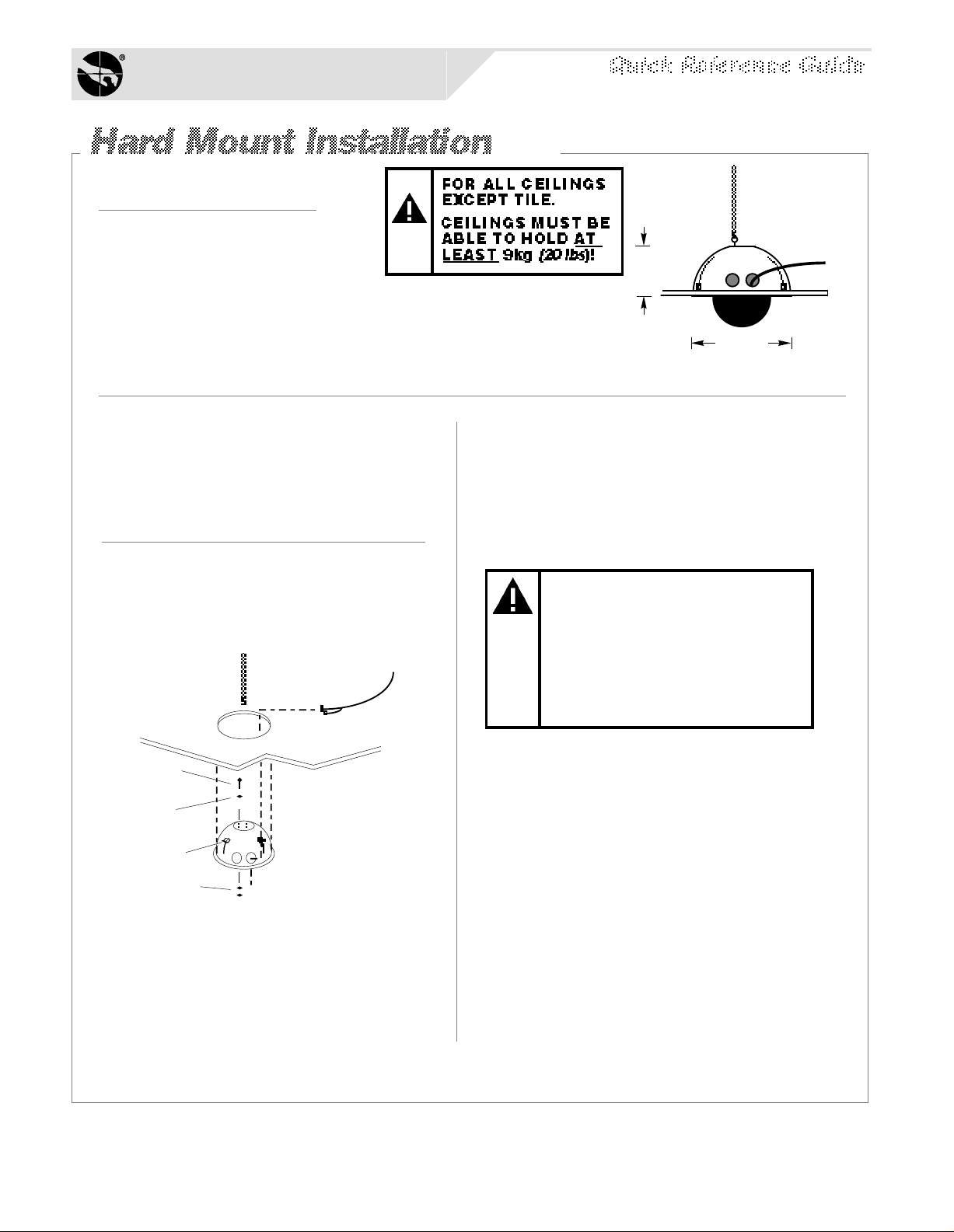
20cm
(8")
39.4cm
(15.5")
MAX
3.
Procedure
IMPORTANT: Shipping box contains a
template—do not throw the template out.
1.
Using the template, scribe a 35.6cm
(14")* hole in the ceiling or tile. Cut out
the hole.
[d]
[e]
[b]
[a]
[f]
[c]
2.
Place a washer [a] over the eyebolt
supplied [b]. Insert the eyebolt into a
hole in the top of the housing and
secure using a washer and nut [c].
*U.S. Customary Measurements in italics are rounded off.
Using an S-hook, hang safety chain [d]
from a strong ceiling member and, using
a second S-hook, attach other end of the
chain to the eyebolt. Keep the chain as
taut as possible. Tighten both ends of
each S-hook.
KEEP CHAIN AS TAUT AS
POSSIBLE! CLOSE ENDS
OF EACH S-HOOK!
DO NOT USE SPRINKLER
OR FIRE CONTROL
SYSTEM SECURING THE
SAFETY CHAIN!
4.
Feed video and multiconductor cables [e]
through one of the two holes in the side of
the housing. Then cover all openings in
the housing with the aluminum tape
supplied.
5.
With the three mounting tabs [f] of the
housing in the up position, insert the
housing into the ceiling hole, then from
inside the housing bring the tabs down
and tighten their screws to secure. The
housing is now ready for chassis
installation (page Q-8).
SENSORVISION SpeedDome
Q-1
Page 4
Sensormatic
SENSORVISION SYSTEMS
Required Parts
Hard Mount Kit
0351-0393-01
Description Qty. Part No.
"S" hook, open
Chain, Navy link
Eye bolt, 10-24 w/nut
Washer, flat, SS #10
Nut, locking, 10x24
Aluminum tape
2
6
1
2
1
4 FT
Adj. Ceiling Mount Kit
0351-0394-01
Support, L-shape
Support, Z-shape
Washer, flat #10
Nut, wing 10-32
Screw, 10-32x3/4
Spacer, Nylon
Adapter plate
Screw, mach. M6x12
2
2
8
8
2
16
1
4
2897-0004
2898-0002
2882-0112
2848-8100-17
2838-9154-05
3200-0115-01
0500-3439-01
0500-3440-01
2848-6301-23
2834-0007-01
2804-7931-05
3110-0016
0500-3982-01
5801-4074-311
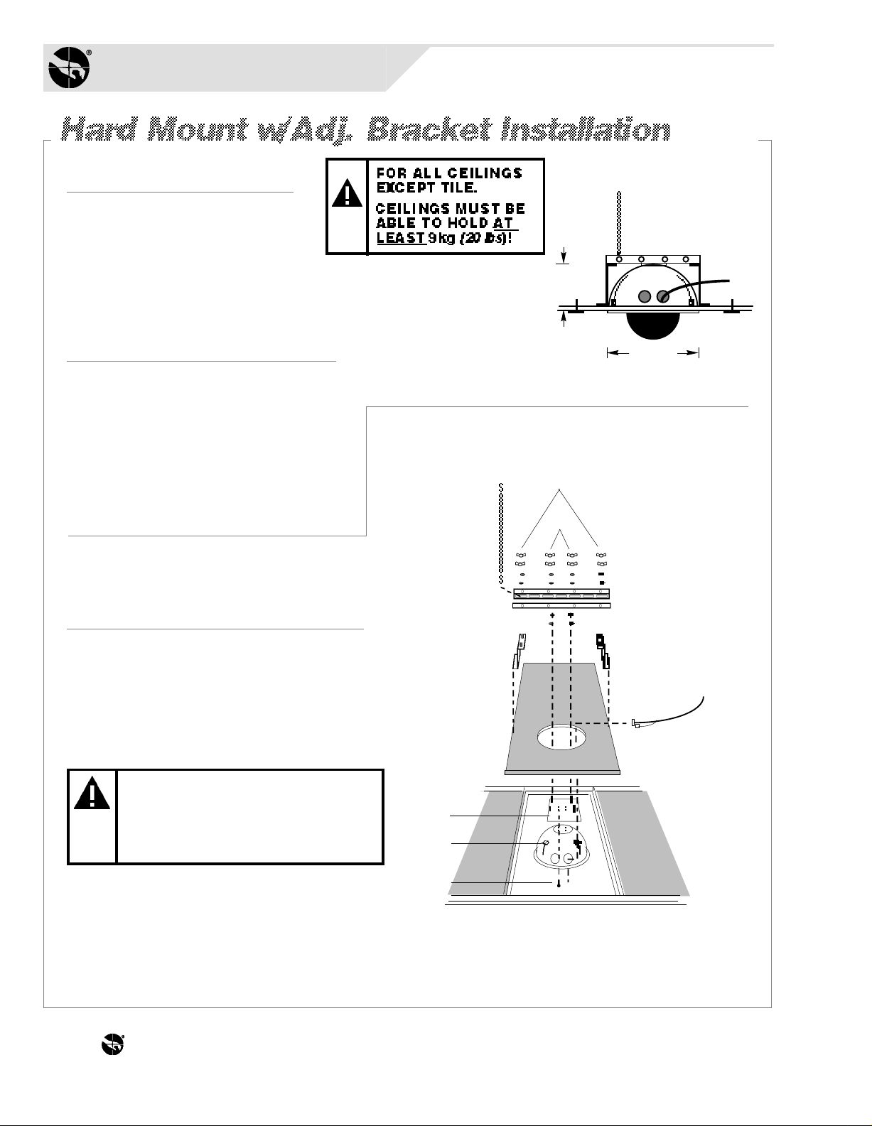
20cm
(7.9")
39.4cm
(15.5")
MAX
[c]
[h]
[i]
Procedure
IMPORTANT: Shipping box contains a
template—do not throw the template out.
1.
Tile ceilings only. Remove the ceiling
tile(s) and inspect the ceiling frame. The
frame must be capable of withstanding 9kg
(20 lbs) of weight and the forces generated
as the dome pans and tilts.
All ceilings. Using the template, scribe a
35.6cm (14") hole in the ceiling or tile. Cut
out the hole.
*U.S. Customary Measurements in italics are rounded off.
*
IF CEILING FRAME
CANNOT SUPPORT DOME,
ASK BUILDING
MAINTENANCE TO INSTALL
ADDITIONAL CEILING
[b]
[f]
[a]
[j]
[e]
[g]
[d]
THE WORLD LEADER IN LOSS PREVENTION Q-2
Page 5
2.
7.
Place "Z" supports [a] on the ceiling's top
surface. For tile ceilings, make sure the
edge of the supports rests flush with edges
of tile. Refer to diagram on page Q-4.
3.
Place the two "L" supports [b]—cut to
length, if necessary—over the threaded
studs of the "Z" supports and fasten
together using four washers and wing nuts
provided [c].
4.
From inside the housing, insert the four
screws [d] provided through the holes in
the top of the housing and into the
adapter plate [e].
5.
Place enough spacers [f] over each stud
in the adapter plate to compensate for
the thickness of the ceiling.
Bring the three mounting tabs of the
housing down and tighten their screws to
secure. Then secure the plate to the "L"
supports using washers and wing nuts [h].
8.
Using an S-hook, hang safety chain [i]
from a strong ceiling member and, using a
second S-hook, connect the other end of
the chain to one of the "L" supports. Keep
the chain taut. Tighten both ends of each
S-hook.
KEEP CHAIN AS TAUT AS
POSSIBLE! CLOSE ENDS
OF EACH S-HOOK!
DO NOT USE SPRINKLER
OR FIRE CONTROL
SYSTEM SECURING THE
SAFETY CHAIN!
9.
6.
With its three mounting tabs [g] in the up
position, insert the housing into the
ceiling hole until the studs in the plate fit
through the slots in the "L" supports.
Feed video and multiconductor cables [j]
through one of the two holes in the side
of the housing. Then cover all openings
in the housing with the aluminum tape
supplied. The housing is now ready for
chassis installation (page Q-8).
SENSORVISION SpeedDome
Q-3
Page 6
Sensormatic
SENSORVISION SYSTEMS
Required Parts
Required Parts
Standard Ceiling Mount
0351-0376-01
Description Qty. Part No.
Bar, ceiling tee
S-hook, open
Chain, Navy link
Tab
Clip, T-bar
1
2
6 FT
2
4
0500-0263-01
2897-0004
2898-0002
0500-0264-04
1400-0033-01
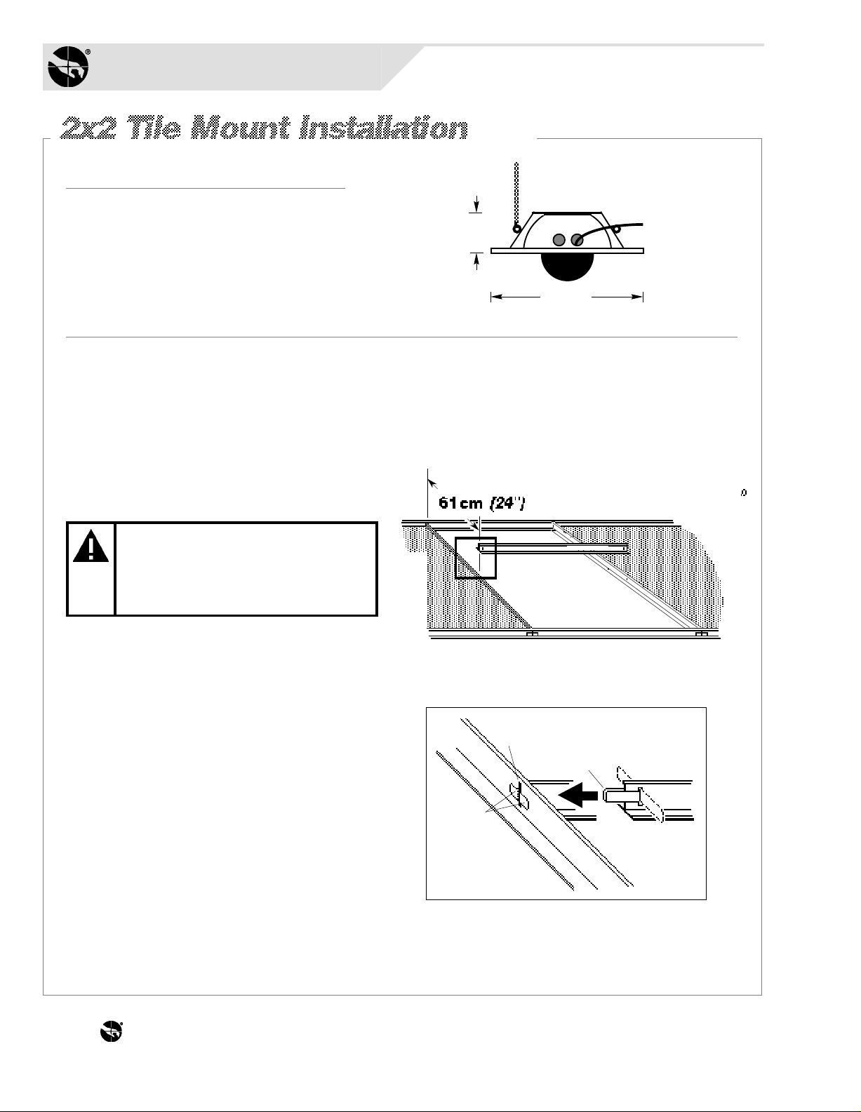
Procedure
1.
Remove the ceiling tile(s) and inspect
the ceiling frame. The frame must be
capable of withstanding 9kg (20 lbs) of
weight and the forces generated as the
dome pans and tilts.
*
19cm
(7.5")
60.7cm
(23.9")
IF CEILING FRAME CANNOT
SUPPORT DOME, ASK
BUILDING MAINTENANCE
TO INSTALL ADDITIONAL
CEILING SUPPORTS.
For 2x2 openings, skip steps 2 and 3.
2.
Cut the 2x4 ceiling tile to 60.3cm (23.75")
using the length of the T-bar supplied [a]
as a guide. Then, attach this T-bar (see
detail) by centering steel tab [b] through
the slot at end of the T-bar. Bend the tab
as shown [c].
3.
Slide the tab through the slot in the
existing frame [d] 61cm (24") from the
T-bar opposite. Bend the ends of the tab
outward [e] to secure. Repeat for the other
end of bar.
[a]
AREA OF DETAIL
[d]
[e]
[c]
[b]
*U.S. Customary Measurements in italics are rounded off.
THE WORLD LEADER IN LOSS PREVENTION Q-4
Page 7
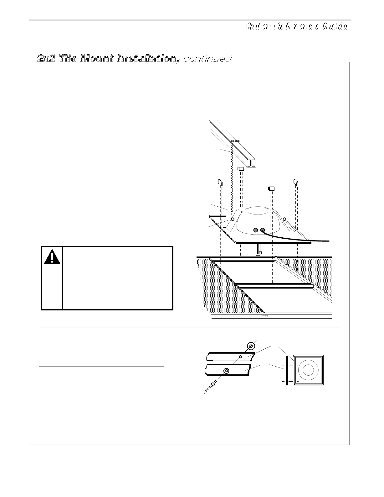
4.
[f]
[m]
[l]
[k]
[j]
[i]
[h]
[g]
KEEP CHAIN AS TAUT AS
POSSIBLE! CLOSE ENDS
OF EACH S-HOOK!
DO NOT USE SPRINKLER
OR FIRE CONTROL
SYSTEM SECURING THE
SAFETY CHAIN!
Set the housing [f] into the ceiling opening. For slightly larger openings, see box
below. If installing in a 2x2 ceiling, remove
an adjacent ceiling tile to aid installation.
5.
Clamp the housing to the T-bars by snapping a T-bar clip [g] over the raised edge of
the housing and the T-bar. Center this clip
along the edge. Repeat for each side of
housing.
7.
Feed video and multiconductor cables [m]
through one of the two holes in side of the
housing and reinstall the adjacent ceiling
tile. See chassis installation on page Q-8.
6.
Wrap safety chain [h] around a strong
ceiling member [i]; attaching it to itself
using an S- hook [j]. Attach the other end of
the chain to one of two eyelets [k] on the
housing using a second S-hook [l]. Keep
the chain as taut as possible. Close both
ends of each hook.
Add extension bars to the
housing for ceiling openings
slightly larger than 2x2 or 2x4.
[D]
[B]
[A]
Extension Bar
0351-0243-01
Description Qty. Part No.
Bar, extension
Rivet, pop .125x.390
Washer, flat No. 5
Bar, ceiling tee
Tab
Clip, T-bar
4
16
16
1
2
4
0500-3326-01
2873-0004-05
2848-1408-01
0500-0648-01
0500-0264-04
1400-0033-01
side view detail
top view[C]
Extension bars [A] mount to the edge of
the housing [B] to provide a proper fit.
Buttjoint as many bars as required using
pop rivets [C] and washers [D], four per
bar, as shown above. Do not use clips.
SENSORVISION SpeedDome
Q-5
Page 8
Sensormatic
SENSORVISION SYSTEMS
Required PartsRequired Parts
Required Parts
Pendent Mount Kit
0351-0392-01
Description Qty. Part No.
1400-0069-01
Flange, 1-1/4" dia.
Fitting, pipe tee
Nipple, short 1-1/4
Anchor bolt, 1/4x2-1/4
w/hardware
Pipe, 1-1/4", straight, 6m
max, threaded both ends
Cap
1
1
1
4
1
1
1417-0040-01
1417-0041-01
2880-0011
CE supplied
0500-3964-01
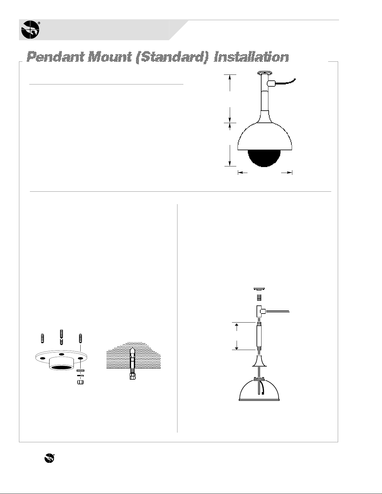
Procedure
1.
Using the flange [a] as a template, mark
hole locations on ceiling for four bolts.
Remove the flange and drill four .64cm
*
(1/4") holes to required depth.
For each hole, screw two nuts onto the
anchor bolt provided, with two threads of the
second nut extend- ing over end of the bolt
to protect the bolt threads from damage [b].
Hammer the bolt into ceiling leaving only
its threads exposed. Remove the nuts and
bolt the flange to the ceiling using the flat
washers, lock washers and nuts supplied [c].
6.1M
(20') MAX
30.4cm
(12")
35.6cm (14")
MAX
3.
Feed video and multiconductor cables [h]
through center hole of pipe tee and down
through the pipe. Note: Remove the CinchJones connector, if used, to enter pipe.
Slip the cap [i] onto the pipe, then thread
housing [j] onto the pipe. See chassis
installation on page Q-8.
[g]
[e]
[h]
[f]
[a]
[c]
[b]
2.
Thread the straight pipe [d] (not supplied)
and nipple [e] into pipe tee [f]. Thread the
nipple of the entire assembly into flange [g].
U.S. Customary Measurements in italics are rounded off.
*
THE WORLD LEADER IN LOSS PREVENTION Q-6
6m (20') max
[i]
[d]
[j]
Page 9
Required Parts
Required PartsRequired Parts
Adjustable I-Beam Clamp Install Kit
0351-0391-01
Description Qty. Part No.
0500-3975-01
12
1
2
4
8
1
1
1
0500-3976-01
5801-4194-311
5840-0500-020
5826-0500-020
1417-0041-01
1417-0040-01
1400-0069-01
Base plate
Clamp plate
Screw, mach. M6x70
Washer, flat
Nut, locking
Fitting, pipe nipple
Fitting, pipe tee
Flange, 1-1/4"
6.1M (20') MAX
30.4cm
(12")
*
35.6cm
(14") MAX
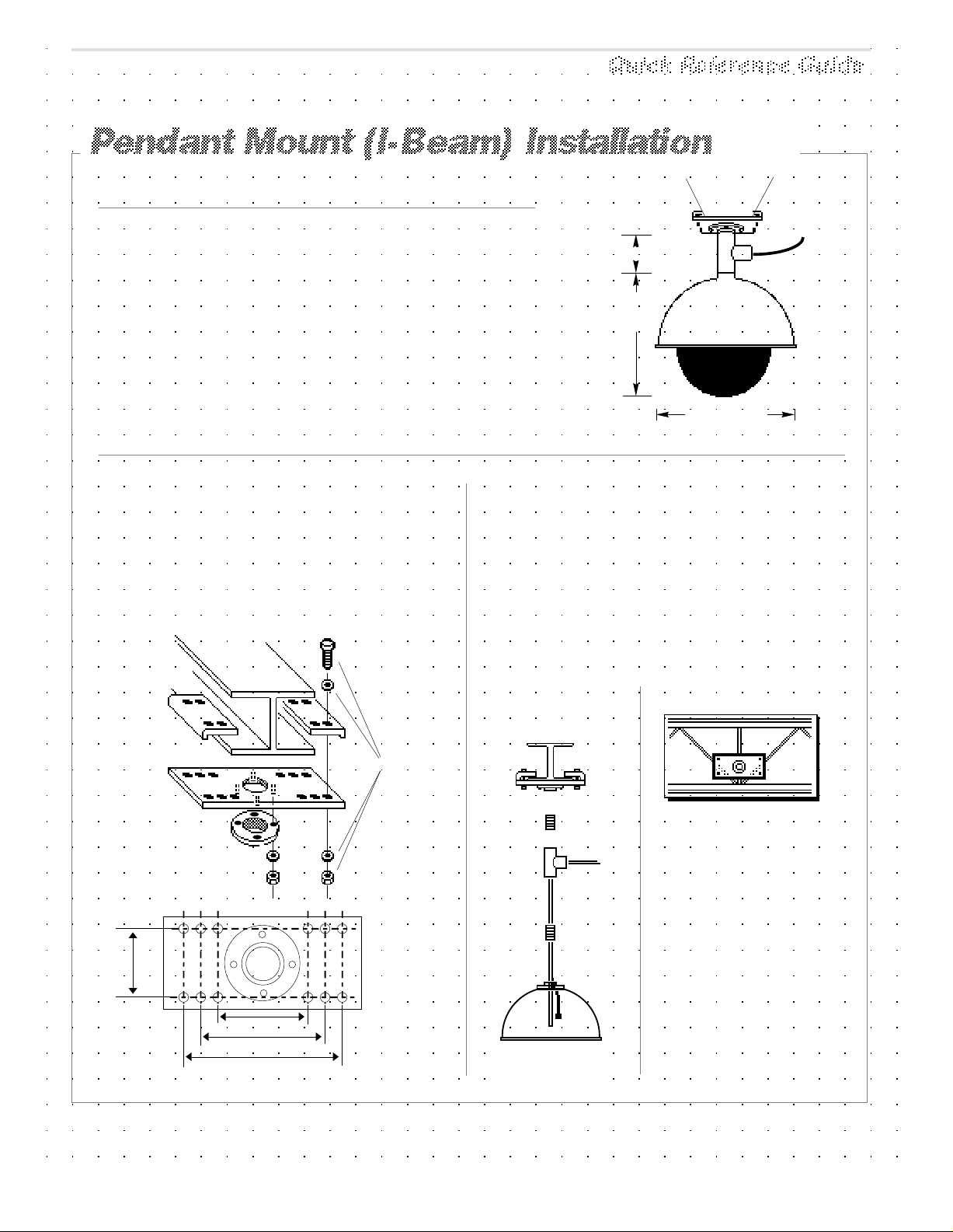
Procedure
I-beam attachment . Set the base plate
[a] against a suitable ceiling member [b].
Secure the plate using clamps [c] and
hardware supplied [d]—see base plate
hole-to-hole dimensions, below. Attach the
flange [e] using hardware supplied [f].
[b]
[c]
[d]
[a]
[e]
Base plate
hole-to-hole
dimensions
[f]
Vertical/Horizontal mounting. Thread
nipples [g] and [h] into the pipe tee [i], and
screw the entire assembly into the base [j].
Next, feed video and multiconductor cables
[k] through center hole of pipe tee. Note:
Remove the Cinch-Jones connector, if used,
to enter pipe.
Finally, thread the housing [l] onto the pipe.
See chassis installation on page Q-8.
Horizontal
Mounting
[j]
[g]
[k]
[i]
Note: If replacing pipe tee
with pipe, cable exiting pipe tee
must be no farther than 15.2cm
(6") from I-beam clamp.
90mm
(3.5")
128mm (5")
179mm (7")
230mm (9")
*
U.S. Customary Measurements in italics are rounded off.
[l]
SENSORVISION SpeedDome
Q-7
Page 10
Sensormatic
SENSORVISION SYSTEMS
Chassis Installation
Required PartsRequired PartsRequired PartsRequired Parts
SpeedDome Install Kit
0351-0377-01
Description Qty. Part No.
2111-0035-01
Connector, BNC
BNC jack
Nylon Cable Tie
1
1
1
2111-0034-01
6009-0006
Procedure
1.
Snap the ball [a] of the lanyard
hanging from the chassis into the
bracket [b] at the top of the housing.
[b]
[d]
[c]
2.
Squeeze the spring-loaded ejector
pins [c] together to seat the chassis in
the corner receptacles [d]. The PC
board must face the cables exiting
the access holes in the housing.
3.
With the chassis hanging down,
connect the video and multiconductor
cables to their receptacles [e]—refer
to instructions on page Q-19. Do not
use the alarm input connector [f]
unless connecting alarms to domes.
4.
Set the thumbwheel switches [g] to the
appropriate address. Example: for address 16,
Thumbwheel Switches
MSB LSB
P3 P4
1 6
J1
[g]
[j]
[e]
[f]
[a]
[h]
[k]
4 plcs.
[i]
Alarm
Input
AC
Video
THE WORLD LEADER IN LOSS PREVENTION Q-8
and
Data
(continued on page Q-9)
Page 11

5.
Attach the skirt assembly or optional
bubble assembly [h] to the chassis by
inserting its T-lanyard into a slot [i] on the
chassis until both ends catch securely.
6.
To lock the chassis in the housing,
squeeze ejector pins [j] and swing the
chassis all the way up, while easing the
cables up through the access holes.
Release these pins into the remaining
corner receptacles.
EJECTOR PINS MUST BE
FULLY INSERTED IN
THEIR RECEPTACLES.
7.
Snap the four pins of the skirt (or bubble)
assembly into the four chassis
receptacles [k].
8.
To compensate for accidental jarring
during assembly, recalibrate the dome
as follows:
At the console, call up the
a.
dome address number.
Press and hold the FAST key.
b.
Then—in order—press and
hold the ZOOM OUT,
FOCUS FAR, and IRIS OPEN
keys.
When the dome begins to pan
and tilt, release the keys.
Once calibrated, which takes about
a minute, the dome is ready for use.
Installation is complete.
SENSORVISION SpeedDome
Q-9
Page 12
Sensormatic
SENSORVISION SYSTEMS
Required Parts
Over Roof Install Kit
0351-0279-01
Description Qty. Part No.
Fitting, 90° pipe
Anchor bolt, 1/2x5 1/2"
Anchor, hollow wall, w/ P
Bolt, hex 1/2-13x4"
Washer, lock1/2"
Cable tie, Nylon, 7.5"
Rod, thread 1/2-13x18"
Nut, Hex 1/2-13"
Washer, flat, SS, P, .531ID X 1.25OD
Washer, flat, ST, Z, .812ID X 2.0OD
RTV compound
Pipe sealant
Washer, flat 5/16"
Nut, hex 5/16-18"
Bolt, hex 3/8-16x3/4"
Adaptor, BNC, male to female
Nut, hex, 1.5" pipe w/seal
1
4
3
1
4
10
1
2
2
1
1
1
8
8
2
1
1
0500-3499-01
2880-0049
2880-0074-01
2880-8917-01
2847-0300
6009-0005
0500-2734-01
2838-9117-04
2848-8101-11
2848-1409-16
1600-0001
1600-0095-01
2848-6301-02
2838-9116-01
2880-0082-01
2113-0004
1417-0042-01
[b]
25cm (10")
Other Parts/Assys
Plate, mounting
Bracket, mounting
Base wall/pole mount
Arm, mounting outdoor
Cover, base (optional)
1
1
1
1
1
0500-3637-01
0500-3638-01
0500-3463-01
0200-0173-01
0500-3668-01
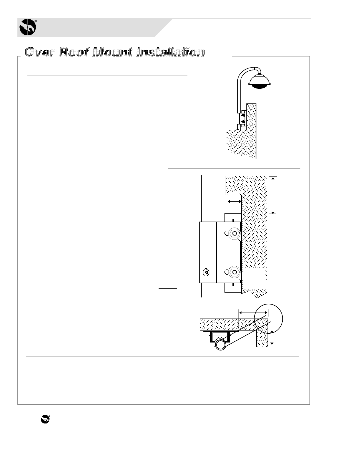
Procedure
Mounting to a solid wall: Mount bracket assembly
[a] to a solid wall or poured concrete cap, where possible.
Mounting to a parapet: Mounting to the inside of
a parapet is preferred. Typically, for the bubble to
clear, mount the base within:
25cm (10") of the top of the parapet.
•
A parapet with a 5cm (2") lip is shown [b].
13cm (5") from the corner of the building [c].
•
Mounting area (including clearance):
Minimum 33cm (13") x 48cm (19").
Note: If the above requirements cannot be
met, mount the dome to the outside of the
wall (a decorative cover can be purchased to
enhance the look of the base). Alternately,
*
(continued on page Q-11)
a 10-inch extender can be screwed into the
end of the pipe, but tell the customer that
increased vibration from wind gusts may
result.
5cm (2")
(top view)
[a]
[c]
(side view)
13cm (5")
Max
8cm (3")
Max
*
U.S. Customary Measurements in italics are rounded off.
THE WORLD LEADER IN LOSS PREVENTION Q-10
Page 13

Place plate [a] in desired location, level, and mark slots. Plate
MUST BE LEVEL. Remove template, then drill four 1/2-inch
holes to the required depth for
type of wall and hardware used.
TOP
[e][d][c]
[a]
For each hole into solid concrete, screw two nuts
[b] onto an anchor bolt, with two threads of second
nut extending over end of bolt to protect threads.
Hammer bolt into wall leaving 1-1/4 inch exposed.
Remove nuts and attach a 1/2-inch flat washer [c],
lock washer [d] and nut [e]. If voids are
encountered, see NOTE below.
Slip slots of mounting plate [f] over bolts,
togglers, or rods [g] and secure using proper
hardware. Mount base [h] to the plate using
hardware provided—any set of four studs can be
used. Feed cables through bottom of bracket [i].
Slip smooth-end of pipe [j] over cable and into
bracket. Secure pipe by tightening screw [k] and
level by adjusting nuts [l]. If using a decorative
cover [m], slide it over pipe.
Apply pipe sealant to pipe threads [n], then slip
elbow [o] over cable and screw elbow onto pipe.
Once on, elbow opening should face down.
Note: Approximately 36cm (14") of cable must
exit elbow. The mount is now ready for housing
and chassis installation on page Q-16.
[m]
Cover
(optional)
[j]
[i]
[k]
[n]
[f]
[l]
[b]
[o]
36cm (14")
[g]
[a]
NOTE: Voids encountered while drilling...
One void only: Insert toggler (provided) through
hole where void ocurred. Insert associated bolt.
A
B
INSERT
metal
channel
thru hole.
PULL
plastic
tab to
seat
channel
C
D
SLIDE
plastic
cap along
tab until
seated
on wall.
SNAP off
plastic
legs at
cap by
pushing
outward.
Two or more voids: For each void, drill hole
through wall. Then, insert threaded rod (provided)
through hole and attach hardware shown. Purchase
additional rods/hardware as required.
MOUNTING BRACKET
GOES HERE
Lock
Washer
Nut
1/2 inch
Flat Washer
SENSORVISION SpeedDome
1/2 inch
Flat Washer
Nut
3/4 inch
Flat Washer
Q-11
Page 14

Sensormatic
SENSORVISION SYSTEMS
Required Parts
Wall Mount Install Kit
0351-0283-01
Description Qty. Part No.
Washer, flat ST, Z, .344IDX.875OD
Nut, hex Nylon-LK CAD 5/16-18
Anchor, wedge, bolt, 1/4 X 2.2
Pipe sealant
Plug, 1-7/8 x 1"
RTV compound
Adaptor, BNC, male to female
Nut, hex, 1.5" pipe with seal
Other Parts/Assys
Pipe, 12 in. long
Base, wall/pole
Support, wall/pole
Fitting, 90° pipe
Corner Bracket Mount only:
Corner Brkt, mounting (optional)
4
4
4
1
1
1
1
1
1
1
1
1
1
2848-6301-02
2838-9116-01
2880-0011
1600-0095-01
0649-0685-01
1600-0001
2113-0004
1417-0042-01
0500-3465-01
0500-3463-01
0500-3464-01
0500-3499-01
0500-3636-01
WALL
MOUNT
(side view)
OPTIONAL
CORNER
BRACKET
MOUNT
(top view)
Procedure
Place wall-mount base [a] or corner bracket
[b] in desired location, level, and mark
mounting holes [c].
Drill four 1/4-inch holes to the required
depth. For each hole:
Screw two nuts onto anchor bolt, with two
•
threads of second nut extending over end
of bolt to protect threads [d].
Hammer bolt into wall leaving 1-1/4
•
inch of bolt exposed. Then, remove
nuts.
Slip base shown or corner bracket over bolts
and secure using hardware [e]. Secure base to
studs of corner bracket, if used. Then loosely
thread a washer and nut [f] onto the four
threaded studs of the base [g].
(continued on page Q-13)
[a]
[c]
(front view) (front view)
(side view)
[b]
[d]
[f]
[e]
[g]
(top view)
THE WORLD LEADER IN LOSS PREVENTION Q-12
Page 15
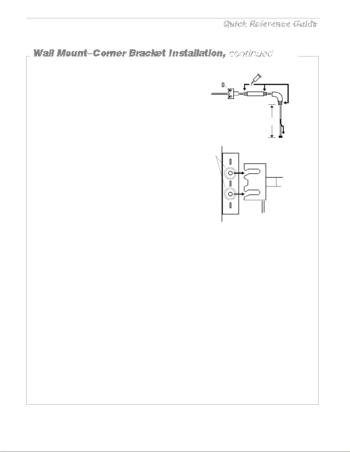
Feed camera dome cables [h] through
mounting bracket (i).
Apply sealant [j] to threads of straight
pipe [k], then slip pipe over cable and
screw pipe into bracket.
Slip elbow [l] over cable and screw elbow
onto pipe. Once on, elbow opening should
face down. Note: Approximately 36cm (14")
of cable must exit elbow. If so, insert plug [m]
and seal with RTV.
[m]
[h]
[i]
*
[j]
[l]
[k]
36cm (14")
Hook bracket [n] on threaded stud between
washer and base [o] while feeding excess
cable [p] back through hole in bracket. Level,
and tighten nuts [q] on both sides of base to
secure.
The mount is now ready for housing and
chassis installation. See page Q-16.
*
U.S. Customary Measurements in italics are rounded off.
[q]
[o]
[n]
[p]
SENSORVISION SpeedDome
Q-13
Page 16
Sensormatic
SENSORVISION SYSTEMS
Required Parts
Pole Install Kit
0351-0282-01
Description Qty. Part No.
2848-6301-02
Washer, flat 5/16"
Nut, hex 5/16-18
Screw, M, HXHD, SS, 1/4 - 20 X 1"
RTV compound
Pipe sealant
Plug, 1-7/8 dia. 1" thick
Adaptor, BNC, jack to plug
Nut, hex 1.5" pipe w/seal
Other Parts/Assys
Pipe, 12 in. Long
Base, Wall/Pole
Support, Wall/Pole
Clamp package (see note)
Fitting, 90° pipe
4
4
2
1
1
1
1
1
1
1
1
2
1
2838-9116-01
2802-8401-72
1600-0001
1600-0095-01
0649-0685-01
2113-0004
1417-0042-01
0500-3465-01
0500-3463-01
0500-3464-01
6010-0043-01
0500-3499-01
Note: Two clamp
packages are provided:
one for the dome, one for
the J-box. Straps in each
package are sufficient
for 10cm (4") to 30.5cm
(12") wide poles. For
larger widths, order an
additional package.
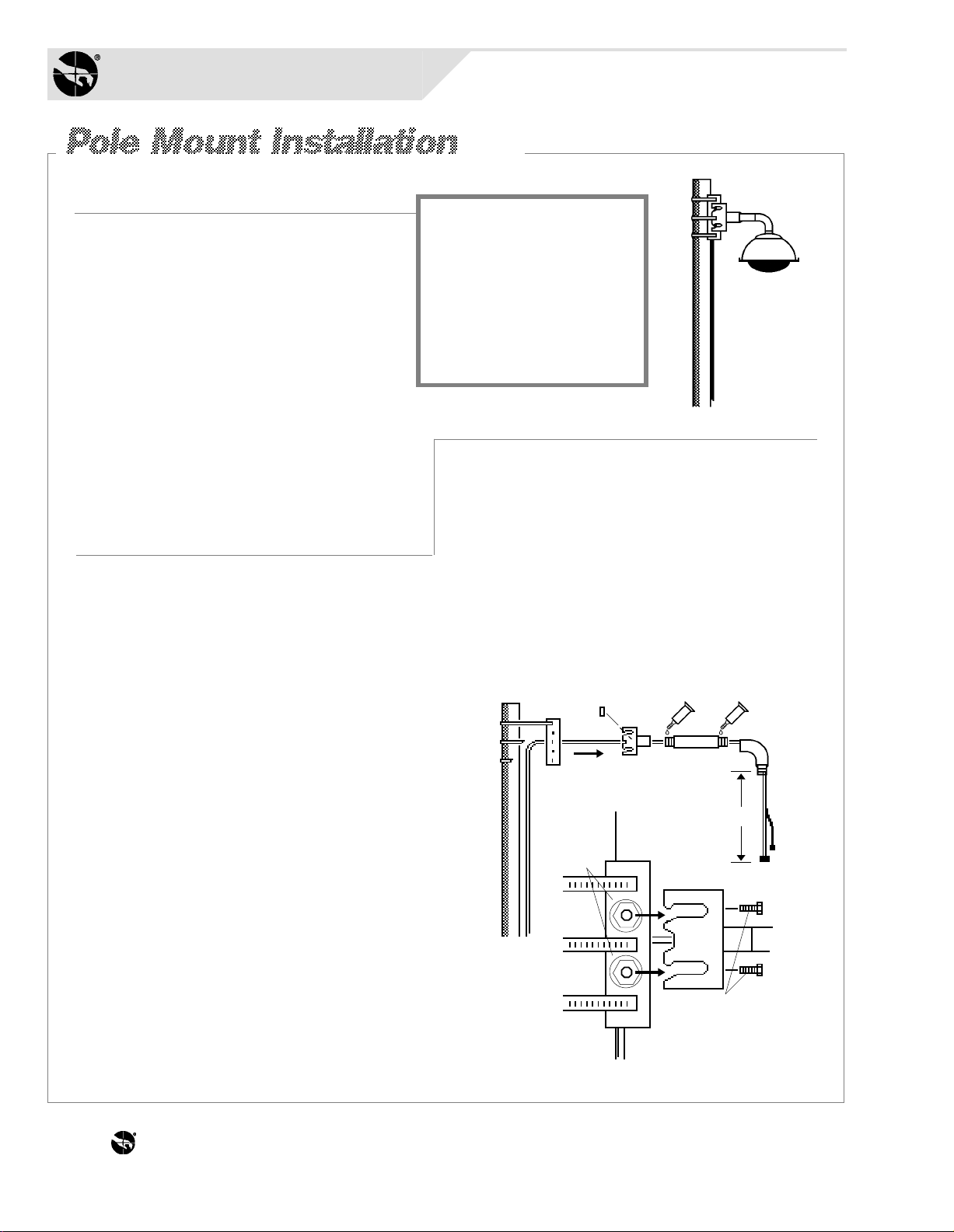
Loosely thread washer and nut [i] onto the
four threaded studs of base [j]. Next, insert
two 1/4-20 leveling screws [k] into bracket
[l]. Then, hook bracket on threaded stud
between washer and base while feeding
excess cable [m] back through hole in base.
Procedure
Procedure
Feed camera dome cables [a] through the
large hole in mounting base [b].
Following the directions on back of the
clamp package (see NOTE above), strap
the mounting base securely to the pole [c].
Feed cables exiting base through the hole
in the mounting bracket [d].
Apply sealant [e] to threads of straight pipe [f],
then slip pipe over cable and screw into
bracket.
Slip elbow [g] over cable and screw elbow
onto pipe. Once on, elbow opening should
face down. Note: Approximately 36cm (14")
of cable must exit elbow. If so, insert plug [h]
into bracket and seal with RTV.
*
U.S. Customary Measurements in italics are rounded off.
Use leveling screws to level. Tighten nuts
on both sides of base to secure. The mount
is now ready for housing and chassis
installation. See page Q-16.
[c]
[b]
[h]
[d]
[e]
[f]
[a]
36cm (14")
[i]
[j]
*
[l]
[k]
[m]
[g]
THE WORLD LEADER IN LOSS PREVENTION Q-14
Page 17
Required Parts
Ceiling Mount Install Kit
0200-0163-01
Description Qty. Part No.
Flange
Fitting, pipe tee
Nipple, short 1-1/2x 2
Anchor bolt, 1/4x2-1/4
w/hardware
Pipe sealant
Plug, 1-7/8 dia., 1" thick
RTV compound
Label, blank, paper, thermal
Adaptor, BNC, male to female
Nut, hex, 1.5" pipe w/seal
1
1
2
4
1
1
1
1
1
1
1400-0058-01
1417-0036-01
1417-0037-01
2880-0011
1600-0095-01
0649-0685-01
1600-0001
2450-0008-01
2113-0004
1417-0042-01
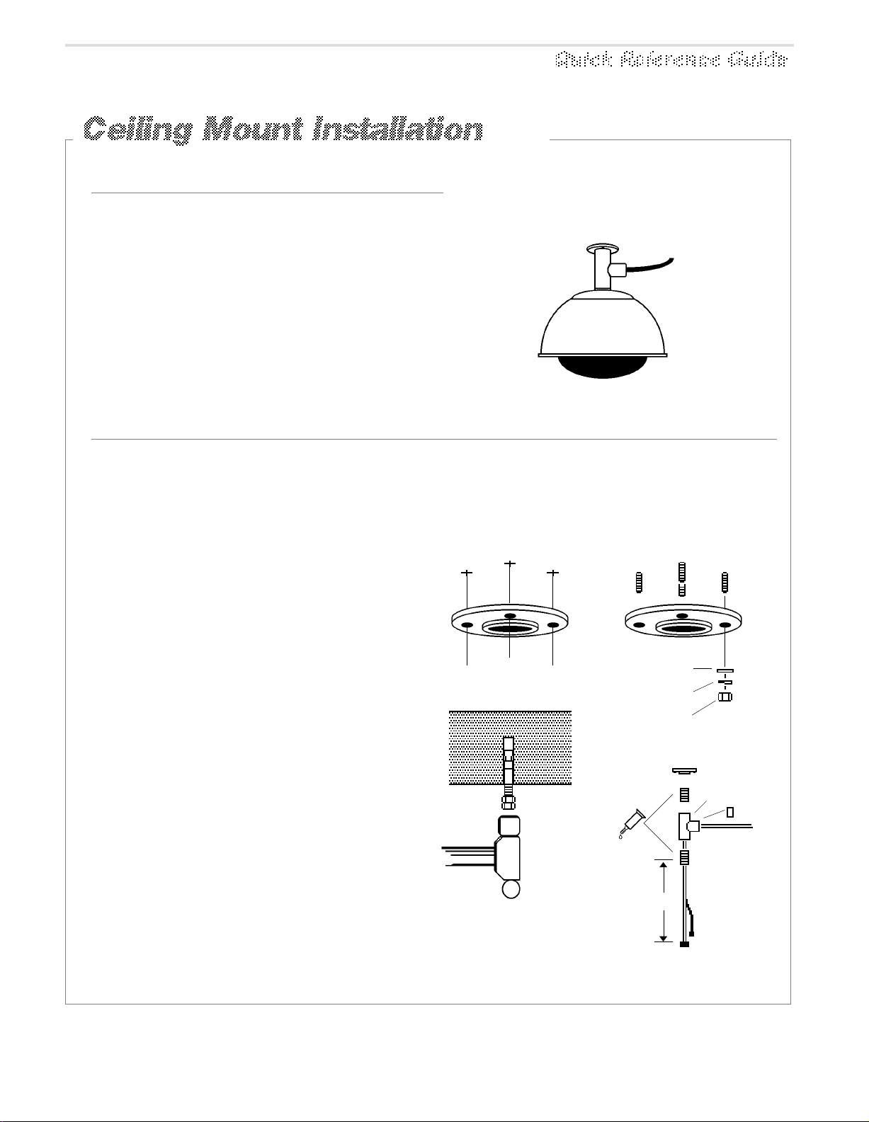
Procedure
Place the mounting flange [a] on the
ceiling in the desired location. Then, using
the flange as a template, mark locations for
four bolt holes. Remove the flange.
Drill four 1/4-inch holes to the required
depth. For each hole, screw two nuts
onto an anchor bolt, with two threads of
second nut extending over end of bolt to
protect threads [b].
Hammer the bolt into the ceiling leaving
1-1/4 inch of bolt exposed. Remove nuts.
Bolt the mounting flange to the ceiling
using a 1/2-inch flat washer [c], lock
washer [d], and nut [e].
Apply pipe sealant to nipples [f], then
screw nipples into the pipe tee [g].
Screw the entire assembly into the flange
[h]. Then, feed the camera dome cables [i]
through the center hole of the pipe tee.
Note: Approximately 36cm (14") of cable
*
must exit the nipple. If so, insert plug [j]
and seal with RTV.
The mount is now ready for housing and
chassis installation. See page Q-16.
[a]
[c]
[d]
[e]
[h]
[b]
[f]
36cm (14")
[g]
[j]
[i]
U.S. Customary Measurements in italics are rounded
*
SENSORVISION SpeedDome
Q-15
Page 18

Sensormatic
SENSORVISION SYSTEMS
1
[a]
Using tamper-proof tool
(T-20), remove captive
bubble attachment screws [a]
from housing, then remove
bubble [b].
[b]
[e]
2
[c]
[d]
[f]
[g]
[h]
Screw 1.5" hex nut [c], with its white (or
yellow) seal facing the cap [d], onto the
pipe. Next, apply pipe sealant [e] to
threads of elbow (or nipple, if this is a
ceiling mount). Then feed the composite cable (f) through the SpeedDome
cap [d] and through the housing [g].
Thread the dome housing onto the
elbow (or nipple), compressing the cap
against the housing until tight. Level as
shown [h]. Apply RTV around the hex
nut.
[j]
3
FEMALE
COMPRESSION-TYPE
CONNECTOR
PN 2109-0254-06
Existing composite cable
from J-Box
Referring to the chart below, replace
the Cinch-Jones connector [i] with
female compression connector [j]
(located at P4 on the SpeedDome
chassis).
Female Compression-Type
Connector
PIN CONNECTIONS
1
brown
2
yellow
3
black
4
red
5
white
6
green
7
orange
7
DESCRIPTIONPI
data out (Lo)
data out (Hi)
ac
Gnd.
ac
data in (Lo)
data in (Hi)
1
[i]
4
[k]
Next, connect the composite cable
compression connector [k] to J2, and the video
connector to J1, on the Outdoor Interface
Board [l], mounted on the outside of the
bracket. Make sure when connecting to this
board, that the screws of the compression
connector are turned toward the inner black
assembly. Tie wrap the composite cable to the
bracket assembly to make way for chassis
installation.
THE WORLD LEADER IN LOSS PREVENTION Q-16
[l]
5
[m]
[n]
Snap the ball of
the lanyard [m]
in- to the
bracket [n] at
the top of the
housing.
(continued on page Q-17)
Page 19

6
Squeeze the spring-loaded ejector pins [n] together to
seat the chassis in the corner receptacles [o]. The
RS422 board [p] must face the SpeedDome interface
board cables [q] inside the housing.
7
Set the thumbwheel switches [r] to the appropriate
address. Example: for address 16,
MSB LSB
P3 P4
1 6
J1
To connect alarm to
an outdoor SpeedDome, add lightning
protection using a
dataline protector,
PN 4815-0021-01.
Alarm
Input
AC and
DataVideo
8
Then, with the camera chassis hanging down,
connect the video and data SpeedDome Interface
Board cables [q] to their receptacles [s]. Do not
use the alarm input connector [t].
9
To lock the chassis in the housing, squeeze ejector
pins [u] and swing the chassis all the way up, while
easing the cables into place. Release these pins
into the remaining corner receptacles.
ENSURE EJECTOR PINS ARE FULLY
INSERTED IN THE RECEPTACLES.
10
Snap the four pins of the skirt assembly [v] into the four
chassis receptacles [w]. Then screw the attachment screws
of the bubble [x] into the three housing receptacles [y].
11
To compensate for accidental jarring during assembly,
recalibrate the dome as follows:
At the console, call up the dome address
a.
number.
Press and hold the fast key. Then—in order—press
b.
and hold the zoom out, focus far, and iris open keys.
[n]
[w]
[o]
[q]
[y]
[p]
[t]
[r]
[s]
[u]
[v]
[x]
When the dome begins to pan and tilt, release the keys.
Once calibrated, which takes about a minute, the dome
is ready for use.
DOME INSTALLATION IS COMPLETE.
SENSORVISION SpeedDome
Q-17
Page 20

Sensormatic
SENSORVISION SYSTEMS
Required Parts
Parts/Assys
Description Qty. Part No.
0400-0529-01
Chassis, Fixed/Drone
Shroud, Fixed
Bubble Kit, Smoked, 9-Inch
Clamp Kit, Adjust. I-Beam
2x2 Indoor Housing
Pendant Indoor Housing
Hard Mount Indoor Housing
1
1
1
1
1
1
1
0500-4218-01
0351-0386-03
0351-0391-01
0200-0176-01
0200-0177-01
0200-0178-01
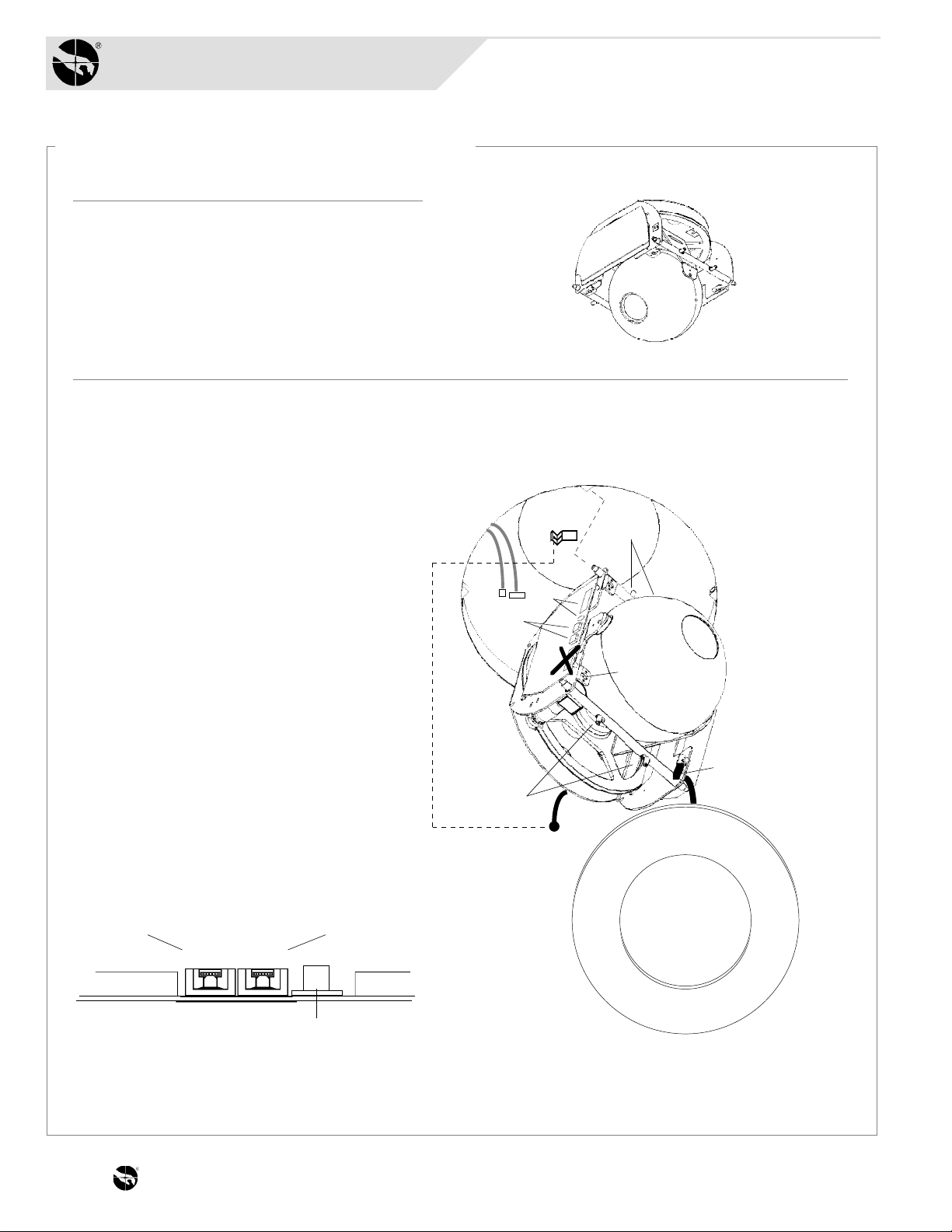
Procedure
1.
Snap the ball of the lanyard [a] into the
bracket at the top of the housing. Then flex
the chassis [b] to insert its mounting studs
into the four corner mounts of the dome
housing to be used: Hard Mount (page Q-1),
2x2 (page Q-4), or I-Beam (page Q-7).
2.
Attach the fixed camera [c] to the swivel
mount. If necessary, move bracket [d] to
turn the camera horizontally (it is not
necessary to loosen the wing nut [e]).
Note: Cover the camera’s LED “on”
indicator with electrical tape.
3.
Using a video test cable and portable monitor,
adjust the camera’s focus and iris using
information provided with the camera. Then,
connect camera video to the console room.
[a]
[e]
[b]
[d]
Swivel Mount
[c]
LED Indicator
[g]
4.
With the studs of the bubble [f] aligned with
the holes in the chassis, nest the shroud [g]
in the bubble and turn its viewing slot so that
the camera lens can see out. Then fasten the
shroud and bubble assembly to the chassis
by placing its studs against the chassis
holes and pressing firmly on the bubble.
THE WORLD LEADER IN LOSS PREVENTION Q-18
[f]
Page 21

Adapting a Composite Cable
for SpeedDome
Replace Cinch-Jones with
female compression-type
connector (supplied with
dome).
FEMALE COMPRESSION-TYPECONNECTOR
PN 2109-0254-06
Existing composite cable
from J-Box
1
7
Female Compression-Type Connector
PIN CONNECTIONS
DESCRIPTIONPI
1
2
3
4
5
6
7
brown
yellow
black
red
white
green
orange
data out (Lo)
data out (Hi)
ac
Gnd.
ac
data in (Lo)
data in (Hi)
WARNING:
Disconnect cable from
power source when
performing cable
conversions.
...or add Patch
PATCH CABLE
PN 0650-0657-01
Extending a
SpeedDome Cable
Add to a length of bulk
composite cable, male and
female compression-type
connectors and male and female
BNCs from SpeedDome Cable
Conversion Kit, 0351-0403-01.
MALE COMPRESSION-TYPECONNECTOR
PN 2109-0271-07
Existing SpeedDome
cable from J-Box
Adapting a SpeedDome
Cable for a Mini-Dome, etc.
Replace female compressiontype connector with
Cinch-Jones connector.
Existing SpeedDome
1
FEMALE BNC
CONNECTOR
PN 2111-0034-01
6
8
(front view)
cable from J-Box
Male and Female
Compression-Type Connectors
PIN CONNECTIONS
DESCRIPTIONPI
1
brown
2
yellow
3
black
4
red
5
white
6
green
7
orange
7
FEMALE
CINCH-JONES
PN 2107-0005-01
12
34
5
7
data out (Lo)
data out (Hi)
ac
Gnd.
ac
data in (Lo)
data in (Hi)
PI
1
2
3
4
5
6
7
8
FEMALE COMPRESSION-TYPECONNECTOR
1
PN 2109-0254-06
7
MALE BNC
CONNECTOR
PN 2111-0033-01
Female Cinch-Jones
PIN CONNECTIONS
DESCRIPTION
orange
green
black
red
white
drain
brown
yellow
data in (Hi)
data in (Lo)
ac
Gnd.
ac
N.C.
data out (Lo)
data out (Hi)
To SpeedDome
SENSORVISION SpeedDome
Q-19
Page 22

THE WORLD LEADER IN LOSS PREVENTION Q-20
Page 23

4.0
4.0
Service
Service
Fault Isolation Checklists, Replacement Parts, Adjustments, and Component
Interconnections in this section:
• Fault Isolation Checklists ..................................................................... Q-21
Video But No Dome Response / Control................................... Q-21
Video / Dome Control But Status Incorrect ............................... Q-22
Loss of Lens Function ............................................................... Q-23
Loss of All Lens Functions ........................................................ Q-24
No Tilt Function ......................................................................... Q-25
No Pan Function / Continuous Pan ........................................... Q-26
No Video But All Functions Work .............................................. Q-27
Poor Video But All Functions Work ........................................... Q-28
Picture Too Light or Too Dark ................................................... Q-29
Dome Targeting Incorrect......................................................... Q-30
Dead Dome............................................................................... Q-31
• Replacement Parts...............................................................................Q-33
Dome CPU Board...................................................................... Q-33
RS422 Interface Board.............................................................. Q-34
Camera/Lens Board.................................................................. Q-35
Monochrome Camera ............................................................... Q-36
Color Camera............................................................................ Q-37
Pan, Tilt, Zoom, Iris, and Focus Motors..................................... Q-38
Clock-Spring Cable...................................................................Q-39
Slip-Ring.................................................................................... Q-40
Power Supply ............................................................................ Q-41
• Adjustments......................................................................................... Q-43
Back Focus ............................................................................... Q-43
Imager Head Cable Reinsertion................................................ Q-44
• Component Interconnections............................................................... Q-45
• Pin-to-Pin Wiring ..................................................................................Q-46
SENSORVISION SpeedDome 4-1
Page 24

4-2 THE WORLD LEADER IN LOSS PREVENTION
Page 25

Sensormatic
SENSORVISION SYSTEMS
Video But No Dome Response / Control
What to check. What to do.
1.
Dome status.
2.
Data at J-Box.
Check the dome # in question for the correct
dome type and condition. If the dome # is
incorrect, reset the dome.
For a new installation, check data wiring at P4
on the RS422 board on the dome.
Use a data tester to test the data line out of
the J-Box. Ensure that the LED status
indicators show good data at each data port. If
an LED indicates bad data, check the data path
back to the control box for improper wiring.
3.
Inside dome.
a. boards and cables.
b. address.
4.
Data into dome.
Make a visual inspection of the inside of the
dome. Ensure that the power and data cables
are properly connected and the boards are
properly seated.
Ensure that the dome is correctly addressed.
Use a data tester to test the data at pins 6
(data Lo) and 7 (data Hi). If data is not present
going into the dome, check the data path back
to the J-Box for improper wiring.
If data is present, replace the RS422 interface
board. If that does not solve the problem,
replace the CPU board. If replacing both
boards does not solve the problem, unplug the
slip-ring connector at JP4 from the CPU board
to ensure that the eyeball connection is not
loading down the system. If this does not solve
the problem, replace the chassis.
NOTE: Testing a chassis at a known working
location will isolate a bad chassis or a bad
connector/cable/J-Box. If a working dome fails
in the bad dome location, the problem is with
the connector/cable/J-Box.
5.
Pan, tilt.
See Q-25 and Q-26.
SENSORVISION SpeedDome
Q-21
Page 26
Sensormatic
SENSORVISION SYSTEMS
Video / Dome Control But Status Incorrect
What to check. What to do.
1.
Dome status.
2.
Data at J-Box.
Check the dome # in question for the correct
dome type and condition. If the dome # is
incorrect, reset the dome.
Disconnect all domes from the J-Box except
the problem dome. Use a data tester to test
the data line out of the J-Box. Ensure that the
LED status indicator shows good data. If the
data tester indicates bad data, check the
wiring path back to the control box for
improper connections.
3.
Data from dome to J-Box.
Use a data tester to test the data at pins 1
(data Lo) and 2 (data Hi) of P4 on the RS422
interface board. If data is not present, replace
the board.
If that does not solve the problem, replace the
CPU board. If replacing both boards does not
solve the problem, unplug the slip-ring
connector at JP4 from the CPU board to
ensure that the eyeball connection is not
loading down the system. If this does not solve
the problem, replace the chassis.
NOTE: Testing a chassis at a known working
location will isolate a bad chassis or a bad
connector/cable/J-Box. If a working dome fails
in the bad dome location, the problem is with
the connector/cable/J-Box.
THE WORLD LEADER IN LOSS PREVENTION Q-22
Page 27

Loss of Lens Function
What to check. What to do.
1.
Connection to camera/lens board.
Verify that the failed operation is isolated to
the suspect dome.
Ensure that the clock spring ribbon cable is
properly connected to the camera/lens board
plug J5.
If the dome does not zoom, focus, iris, or tilt,
replace the camera/lens board with a known
working camera/lens board. Retest.
If some but not all motors are working, replace
the motor in question with a known working
motor. If this solves the problem, replace the
motor.
NOTE: Only zoom/focus/iris motors are
interchangeable.
If the lens functions do not have a full range of
motion, then re-align the motor(s).
2.
RS422 interface board.
3.
Voltage on camera/lens board.
4.
Camera focus.
On the S1 switch pack of the RS422 interface
board, switch position 3 to ON.
If the lens rotation is not smooth with voltage
applied and the lens motor disabled, then
replace the camera lens.
If the dome does not have power, check the
input voltage to the RS422 board. Also check
the DC voltage coming from the dome power
supply to the CPU board. If 12Vdc and 5Vdc are
not present out of the dome power supply,
replace it. If 12Vdc and 5Vdc are present out of
the dome power supply, replace the
camera/lens board.
If the camera does not focus properly while
zooming in and out, adjust the back focus. See
page Q-43.
SENSORVISION SpeedDome
Q-23
Page 28

Sensormatic
SENSORVISION SYSTEMS
Loss of All Lens Functions
What to check. What to do.
1.
Dome switches.
2.
Camera/lens board.
3.
Sprockets.
Ensure that the position of SW3 on S1 of the
RS422 interface board is set to OFF for
enabling lens functions.
Ensure that all connectors to and from the
camera/lens board are properly seated. If
that does not solve the problem, replace the
camera/lens board.
Check to see if the sprockets are hung up and
adjust them accordingly. If the motor gears
are too tight, adjust the gaps of the sprockets
and gears with a 1/4 watt resistor lead. See
page Q-37.
THE WORLD LEADER IN LOSS PREVENTION Q-24
Page 29

No Tilt Function
What to check. What to do.
1.
Connection to P1.
2.
Sprocket.
3.
Tilt motor when the tilt function is
commanded.
4.
Data when the tilt function is
commanded.
Reset the dome and observe the orientation
(tilt). Verify that the motor is connected to P1
on the camera/lens board.
Check to see if the sprocket moves freely and
adjust it accordingly. If the motor gear is too
tight, adjust the gap distance of the sprocket
and gear with a 1/4 watt resistor lead. See
page Q-38.
Plug a known working tilt motor into P1. If the
motor works with the tilt command, replace
the tilt motor. If the tilt motor does not work,
replace the camera/lens board.
If no data is present, check the data path for
improper wiring.
NOTE: Tilt motors are not interchangeable
with other motors.
SENSORVISION SpeedDome
Q-25
Page 30

Sensormatic
SENSORVISION SYSTEMS
No Pan Function / Continuous Pan
What to check. What to do.
1.
Connection to P3.
2.
Sprocket.
3.
Pan motor when the pan function
is commanded.
Reset the dome and observe the orientation
(pan). Verify that the motor is connected to
P3 on the CPU board.
Check to see if the sprocket moves freely and
adjust it accordingly. If the motor gear is too
tight, adjust the gap distance with a 1/4 watt
resistor lead. Ensure that it rotates smoothly
without power applied to the dome.
Plug a known working pan motor into P3. If
the motor works with the pan command,
replace the pan motor. If the pan motor does
not work, replace the dome CPU board.
4.
Data when the pan function is
commanded.
5.
Slip-ring assembly.
If no data is present, check the data path for
improper wiring.
If the camera continuously pans when the
stop or reset command is issued, replace the
slip-ring assembly.
NOTE: Pan motors are not interchangeable
with other motors.
THE WORLD LEADER IN LOSS PREVENTION Q-26
Page 31
No Video But All Functions Work
What to check. What to do.
1.
Iris adjustment from controller.
2.
RS422 board.
3.
Clock spring ribbon cable.
4.
Voltages/zoom, focus, and iris
functions.
Open the iris and verify that video is present.
Check for the presence of video out of the
RS422 board. If video is coming out of the
RS422 board, check the J-Box, composite/
video cable and monitors for the problem.
If video is not coming from the RS422 board,
check for visual damage to the ribbon cables
and verify that the iris is operating.
Ensure that the clock spring ribbon cable is
correctly connected to the camera lens
board.
If voltages are not present and/or the zoom,
focus, and iris functions are not working,
replace the camera/lens board.
If replacing the camera/lens board does not
solve the problem, replace the camera.
SENSORVISION SpeedDome
Q-27
Page 32

Sensormatic
SENSORVISION SYSTEMS
Poor Video But All Functions Work
What to check. What to do.
1.2.Video, gray "Humbar."
Monitor
Video, no sync.
If the monitor is a dedicated (full time)
monitor, remove the looping video and set the
termination switch to 75 ohms.
If that does not correct the problem, isolate
the ground lug on the monitor power cord
using a 2-cond extension cord. DO NOT cut or
damage the line cord. If isolation of the
ground lug corrects the problem, order and
install a ground loop transformer (isolation
transformer).
If the video coming in directly from the dome
is poor, set the switches on the RS422
interface board to LL, SW5 on S1.
If the video coming in directly from the dome
is good, but the customer monitor video is
poor, check monitor, cabling, and connectors
for improper connections.
NOTE: Keep at least 1.5m (5') from high
voltage lines, flourescent lights, neon lights,
etc. when installing video and data cables. If
you must cross a 110Vac line, do so at right
Monitor
THE WORLD LEADER IN LOSS PREVENTION Q-28
angles to the cable.
NOTE: Use a quality coaxial cable (Beldon
8241 or equivalent).
Page 33

Picture Too Light or Too Dark
What to check. What to do.
1.
Iris adjustment at controller.
2.
S1 switch pack.
3.
Iris control.
4.
Video cable.
Open or close the iris at the controller to suit
or reset the iris to auto function by holding
the iris open and close buttons at the same
time.
Ensure that the settings of the S1 switch
pack on the RS422 board are 3 and 4 (off).
Verify that the iris control is working properly.
If the motor sprocket is jammed, make the
appropriate adjustments to the sprocket. See
page Q-38.
Plug the focus motor into the iris motor jack.
If the camera focuses when you use the iris
control, replace the iris motor. If the camera
does not focus when you use the iris control,
replace the camera/lens board.
If the video cable has been spliced too many
times, it could adversley effect the video
signal.
The dome looses approximately 3db of video
signal for each splice.
5.
Terminations.
The maximum allowable distance for video
cable between a dome and monitor is 305m
(1000').
Ensure that the video lines are properly
terminated.
SENSORVISION SpeedDome
Q-29
Page 34

Sensormatic
SENSORVISION SYSTEMS
Dome Targeting Incorrect
What to check. What to do.
1. Check the service history of the dome to see
Dome service history.
if it has been replaced recently. Re-download
the software from the console to the dome.
The dome may have been put back into the
housing in reverse. Also check to see if the
dome is shifting in the ceiling. If it is shifting,
install the necessary clips. If it is a pendant
mount, you may need to secure it with wires
to keep it from swinging or swaying.
THE WORLD LEADER IN LOSS PREVENTION Q-30
Page 35

Dead Dome
What to check. What to do.
1.
Composite cable at J-Box.
2.
Voltage on RS422 interface board.
3.
Voltage on CPU board.
Make a visual inspection of the J-Box to
ensure that the composite cable is connected
properly. Unplug the cable and wait 45 sec.
Plug the cable back in and test dome
operation.
Check the voltage (22Vac min.) at pins 3 and
5 of P4 on the RS422 interface board. If
voltage is not present, check the J-Box for
improper wiring and the dome power supply.
If that does not solve the problem, check
voltage (22Vac min.) at pins 1 and 3 of P5 on
the RS422 interface board. If voltage is not
present, replace the board.
Check pins 2 and 3 of P2 on the CPU board for
12Vdc and pins 1 and 2 for 5Vdc. If voltage is
not present, replace the fuse on the dome
power supply. If that does not solve the
problem, replace the dome power supply
assembly.
If that does not solve the problem, disconnect
JP4 from the CPU board. Check the dome for
pan control. If it does not have pan control,
replace the CPU board.
4.
Camera/lens board.
Disconnect J5 on the camera/lens board.
Check the dome for pan control. If it does not
have pan control, replace the clock spring
assembly and/or the slip-ring assembly.
If that does not solve the problem, replace
the camera/lens board. If that does not solve
the problem, replace the chassis.
SENSORVISION SpeedDome
Q-31
Page 36

THE WORLD LEADER IN LOSS PREVENTION Q-32
Page 37

WARNING: Unexpected pan
and tilt can cause injury or
damage the dome during
servicing. To prevent such
movement, always disconnect
power/data connector P4 from
the RS422 interface board
1.
[a]
[e]
[d]
JP4
Remove the RS422
interface board (page
Q-34). Then remove the
CPU board by first
disconnecting
the slip ring [a], pan
motor [b], and power
supply cables [c], then
removing two M3x10
screws
[d] and two standoffs [e].
[d]
[e]
2.
Secure the new board using the
screws and standoffs. Then
connect the following three cables:
• Slip ring cable to JP4,
• Pan motor cable to P3,
• Power supply cable to P2.
DOME CPU BOARD REPLACEMENT IS COMPLETE.
Dome CPU Board
0301-0478-01
[c]
P2
[b]
P3
3.
Reinstall the RS422 interface board
(go to page Q-34).
SENSORVISION SpeedDome
Q-33
Page 38

Sensormatic
SENSORVISION SYSTEMS
WARNING: Unexpected pan
and tilt can cause injury or
damage the dome during
servicing. To prevent such
movement, always disconnect
power/data connector P4 from
the RS422 interface board
1.
Disconnect all cables from the RS422
interface board.
2.
On the new board, set S1 DIP switches to
the same settings (if different) as the
board to be replaced.
P2
S1
P5
P1
Note: S1 factory settings are listed on
a label affixed to the chassis.
3.
Disconnect this board from the dome
CPU board by removing its two M3x10
mounting screws [a].
Note: If removing the RS422
interface board in order to
replace the dome CPU board,
go to page Q-33, then return to
this page and complete step 4.
4.
Noting its orientation, plug in the new
board and reinstall the two mounting screws.
Then reconnect cables in the following order:
• Video cable to J1,
• AC power out cable to P5,
• External sync, if used, to P1,
• Alarm out cable, if used, to P2,
• Alarm in cable, if used, to P3, and last
• AC power/data cable to P4 (see WARNING).
Dome CPU Board
P4P3 J1
[a]
WARNING: Connecting the AC
power/data cable will cause the
dome to immediately pan and
tilt.
THE WORLD LEADER IN LOSS PREVENTION Q-34
5.
Reassemble the SpeedDome chassis
and recalibrate.
Page 39

WARNING: Unexpected pan
and tilt can cause injury or
damage the dome during
servicing. To prevent such
movement, always disconnect
power/data connector P4 from
the RS422 interface board
1.
Remove the lens and camera shrouds (four
screws each). Then disconnect all six cables
from the old camera/lens board [a]. Next, remove
the three M3x10 screws [b]from the board and
the M3x10 screw and nut [c]connecting the
voltage regulator to the eyeball casting.
2.
To avoid pulling the voltage regulator out of
the board, first secure the new board to the
eyeball casting using three screws [b]. Then
reattach the regulator to the eyeball casting
using the M3x10 screw and nut. Finally,
reconnect the following six cables (dressing
them as shown):
• Tilt motor cable to P1.
• Zoom motor cable to J2.
• Focus motor cable to J3.
• Iris motor cable to J4.
• Camera cable to P6.
• Clock spring cable to J5.
Reassemble the lens and camera shrouds
using the eight screws. CAMERA/LENS
BOARD REPLACEMENT IS COMPLETE.
[b]
Screw connecting
regulator to
eyeball casting
[c]
J5
[b]
[c]
J3
[b]
Camera/Lens Board
0301-0204-01
J2
P6
[a]
J4
Iris Ring
Zoom Ring
Focus Ring
P1
3.
Reassemble the SpeedDome chassis and
recalibrate.
SENSORVISION SpeedDome
Q-35
Page 40

Sensormatic
SENSORVISION SYSTEMS
WARNING: Unexpected pan
and tilt can cause injury or
damage the dome during
servicing. To prevent such
movement, always disconnect
power/data connector P4 from
the RS422 interface board
WARNING: The camera is
sensitive to ESD. Use a ground
strap when installing.
1.
Remove the lens and camera shrouds (four
screws each). Then remove two M3x8 screws
[a] from the back of the camera [b] and
unplug its connector from P6 on the
camera/lens board [c].
2.
Lift the camera off the back of the lens and
replace it with a new one. Reinstall the two
screws and reconnect its cable to P6 on the
camera/lens board.
3.
Restore power by plugging connector P4 into the
dome. The dome will return to its home position.
4.
Check backfocus by zooming in on a distant
object and focusing as clearly as possible, then
zooming out. If the picture is out of focus, see Back
Focus Adjustment, page Q-43. If OK, continue.
P6
[a]
[c]
Monochrome
Camera
1/2" CCD EIA, 60Hz
2003-0026-01
1/2" CCD CCIR, 50Hz
2003-0026-02
[b]
Iris Ring
Zoom Ring
5.
Reassemble the lens and camera shrouds using
the eight screws. CAMERA REPLACEMENT IS
COMPLETE.
6.
Reassemble the SpeedDome chassis and
recalibrate.
THE WORLD LEADER IN LOSS PREVENTION Q-36
Focus Ring
Page 41

WARNING: Unexpected pan
and tilt can cause injury or
damage the dome during
servicing. To prevent such
movement, always disconnect
power/data connector P4 from
the RS422 interface board
WARNING: The color camera
imager head is both delicate
and sensitive to ESD. Use a
ground strap when installing.
Be careful not to dislodge its
ribbon cable from the camera.
1.
Remove the lens and camera shrouds (four screws
each). Then remove the old camera [a] by first
unplugging its grey ribbon cable [b] from P6 on the
camera/ lens board, by removing four M3x10
screws [c], and finally, removing the two M2x6
screws [d] securing the imager head to the lens.
Gently lift the camera away from the casting.
2.
Detach the PCI board from the old camera by
removing two M3x10 screws [e], and unplug the
J3 cable. Reassemble this board into the new
camera using the same two screws.
3.
With the grey ribbon cable hugging its chassis,
gently position the new camera into the eyeball
casting. Secure the camera using the four
previously removed screws. Connect the grey
ribbon cable to P6 on the camera/lens board.
4.
Noting how the imager head cable is looped, plug
the imager head onto the back of the lens. Then,
using the two previously removed screws to secure
the imager head.
5.
Restore power by plugging connector P4 into the
dome. The dome will return to its home position.
Color Cameras
1/2" CCD NTSC, 60Hz
2003-0027-01
1/2" CCD PAL, 50Hz
2003-0027-02
[c]
Imager
Head
Note how
imager
head ribbon
cable is
looped.
[d]
[a]
[b]
PCI Board
P6
Focus Ring
6.
Check backfocus by zooming in on a distant object
and focusing as clearly as possible, then zooming
out. If the picture is out of focus, see Back Focus
Adjustment, page Q-43. If OK, continue.
7.
Reassemble the camera and lens shrouds using
the eight screws. CAMERA REPLACEMENT IS
COMPLETE.
8.
Reassemble the SpeedDome chassis and
recalibrate.
Camera
cable must
hug
camera
chassis as
camera is
positioned
into eyeball
casting.
[e]
Iris Ring
Zoom Ring
SENSORVISION SpeedDome
Q-37
Page 42

Sensormatic
SENSORVISION SYSTEMS
WARNING: Unexpected pan
and tilt can cause injury or
damage the dome during
servicing. To prevent such
movement, always disconnect
power/data connector P4 from
the RS422 interface board
Remove the lens and camera shrouds (four screws each). Then
remove the motor suspected of being defective. Tilt, zoom, focus
and iris motors secure to the eyeball casting using two M3x10
screws each. The pan motor secures to the carriage assembly.
Refer to the notes and diagrams for exact motor placement.
Note: Outline the bracket of the old motor with a pencil
before removing to simplify the alignment of the new motor.
Note: When installing screws in the zoom, focus and
iris motors, use the round hole [a] to align the motor,
then use the oblong hole [b] to adjust the gear mesh.
Note: Calibrate gear mesh using a 1/4-watt
resistor or .05mm (.02") dia. drill rod.
Iris Ring
Zoom Ring
Focus Ring
Note: Zoom, focus and iris motors are identical
and can be exchanged when troubleshooting.
Unless only the pan motor was replaced, reassemble
the lens and camera shrouds using the eight screws.
Then reassemble the SpeedDome chassis and
recalibrate.
Zoom Motor
3501-0008-01
[a]
[b]
Pan Motor
3501-0009-01
Focus
Tilt Motor
3501-0010-01
Motor
3501-0008-0
Iris Motor
3501-0008-01
THE WORLD LEADER IN LOSS PREVENTION Q-38
Page 43

Remove the lens and camera shrouds (four
screws each). Next, detach the old clockspring cable by unplugging it from the J5
connector on the camera/ lens board [a] and
by removing two M3x10 screws [b] securing it
to the base of the yoke bracket. Then unplug
the cable from the slip ring connector [c],
unwind it, and slip it out of the retainer/spool
assembly [d].
2.
The new cable has an inked marking [e] on
it. Crease the cable along this marking to
form a 90° bend. Holding the cable’s male
connector [f] in your hand, insert the bend
into the retainer as shown in the detail.
Connect the cable’s male connector to the
slip ring connector at the base of the yoke
bracket and secure it using the previously
removed screws. Dress the cable’s female
end [g] clockwise around the spool approximately 1-1/2 times and connect its connector to J5 on the camera/lens board.
3.
Reassemble the SpeedDome chassis and
recalibrate.
5.
WARNING: Unexpected pan
and tilt can cause injury or
damage the dome during
servicing. To prevent such
movement, always disconnect
power/data connector P4 from
the RS422 interface board
before servicing.
IMPORTANT:
It is not necessary
to disassemble the
eyeball assembly
from the carriage
assembly to
perform this task.
Eyeball assembly is
shown
disassembled for
explanation
purposes only.
[a]
[d]
[c]
[b]
1.
AREA OF DETAIL
Bend
Retainer/
Spool Assy.
To slip ring
connector at
yoke bracket.
To J5,
cam./lens bd.
Male Connector
Female
Connector [g]
[f]
[e]
Reassemble the lens and camera shrouds
using the eight screws. CABLE REPLACEMENT IS COMPLETE.
Cable Assy.
0650-0623-01
4.
SENSORVISION SpeedDome
Q-39
Page 44
Sensormatic
[e]
[g]
[c]
[a]
[b]
[d]
Slip Ring Assy.
2100-0004-01
[f]
[h]
SENSORVISION SYSTEMS
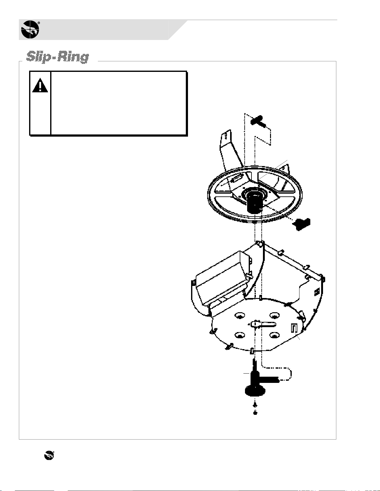
WARNING: Unexpected pan
and tilt can cause injury or
damage the dome during
servicing. To prevent such
movement, always disconnect
power/data connector P4 from
the RS422 interface board
1.
Ready the old slip-ring assembly for removal by unplugging its
female connector [a] from the clock-spring cable connector
at the yoke bracket, unplugging its ribbon cable [b] from JP4
of the dome CPU board, and by removing its two M3x8
screws [c] from at the base of the carriage assembly.
2.
Cut the tie wrap [d] and remove the old slip ring [e] and
washer [f] while carefully feeding its female connector
down through the slip-ring receptacle [g].
3.
Insert the new slip ring by carefully inserting its female
cable connector through the receptacle (making sure
the washer [f] stays at the end of the slip ring as it
enters the receptacle). Then position the slip-ring
ribbon cable in the slot of the receptacle and slowly
turn the slip ring clockwise approx. 3/4-turn until its
flange [e] firmly seats against the carriage assembly.
Secure the slip ring using the two screws.
4.
Connect the cable exiting the end of the receptacle
to the clock-spring cable connector and tie wrap it
[d] to the chassis. Then slip the ribbon cable into its
retaining notch [h] and connect it to JP4 of the dome
CPU board.
SLIP-RING ASSY. REPLACEMENT IS COMPLETE.
5.
Reassemble the SpeedDome chassis and recalibrate.
THE WORLD LEADER IN LOSS PREVENTION Q-40
Page 45

WARNING: Unexpected pan
and tilt can cause injury or
damage the dome during
servicing. To prevent such
movement, always disconnect
power/data connector P4 from
the RS422 interface board
1.
Disconnect power supply cables from P5 [a]
on the RS422 interface board and from P2 [b]
on the dome CPU board.
2.
Cut the tie wraps [c] to release the
cables from the chassis.
[a]
3.
Detach the supply by removing four
M3x10 screws [d] from the corner tabs.
4.
Attach the new supply to the chassis
using the four screws previously
removed. Then secure its cables along
the chassis, as shown, using six new tie
wraps.
[b]
[c]
6 Places
5.
Plug the cable having the large connector into
P5 on the RS422 interface board and the other
cable into P2 on the dome CPU board.
POWER SUPPLY REPLACEMENT IS COMPLETE.
6.
Reassemble the SpeedDome chassis and
recalibrate.
Power Supply
5606-0002-02
SENSORVISION SpeedDome
[d]
Q-41
Page 46

THE WORLD LEADER IN LOSS PREVENTION Q-42
Page 47

WARNING: Unexpected pan
and tilt can cause injury or
damage the dome during
servicing. To prevent such
movement, always disconnect
power/data connector P4 from
the RS422 interface board
WARNING: If servicing a color
camera, be careful not to
disturb the copper-colored
imager cable exiting the imager
Before you begin:
Does the dome use a bubble? If so, remove
the contact eye (if used) and adjust the back focus
of the camera through the bubble. If not, adjust
back focus of the camera through the contact eye.
Focus Ring
Zoom Ring
Iris Ring
Please note: Cameras should not require
adjustment in the field. However, if a camera
image that is focused when zooming in does not
stay in focus when zooming out, perform the
following mechanical adjustment.
1.
Remove the lens and camera shrouds (four screws
each). Then, using the appropriate tool*, loosen the
back focus setscrew (just beneath the back focus
wheel). This screw keeps the wheel stationary.
2.
Restore power by plugging connector P4 into the
dome. The dome will return to its home position.
3.
Disable the lens motors for manual adjustment by
flipping S1, switch 3 on the RS422 board to ON
(disable).
4.
Connect a monitor to the video out BNC (J1 on
RS422 interface board) and manually open the
iris completely.
.035 Allen Wrench for set screw (old version) or
*
screwdriver for Phillips Head screw (new version).
Back focus
Screw
Back focus
Wheel
5.
Manually zoom in on a distant object, focus as
clearly as possible, then zoom out. Next, focus
the picture by turning the back focus wheel
clockwise or counterclockwise for best picture.
Repeat this procedure until the camera stays in
focus through the entire zoom range.
6.
Turn S1, switch 3 on the RS422 interface board
to OFF (enable).
7.
Reassemble the lens and camera shrouds using
the eight screws. BACK FOCUS ADJUSTMENT
IS COMPLETE.
8.
Reassemble the SpeedDome chassis and
recalibrate.
SENSORVISION SpeedDome
Q-43
Page 48
Sensormatic
SENSORVISION SYSTEMS
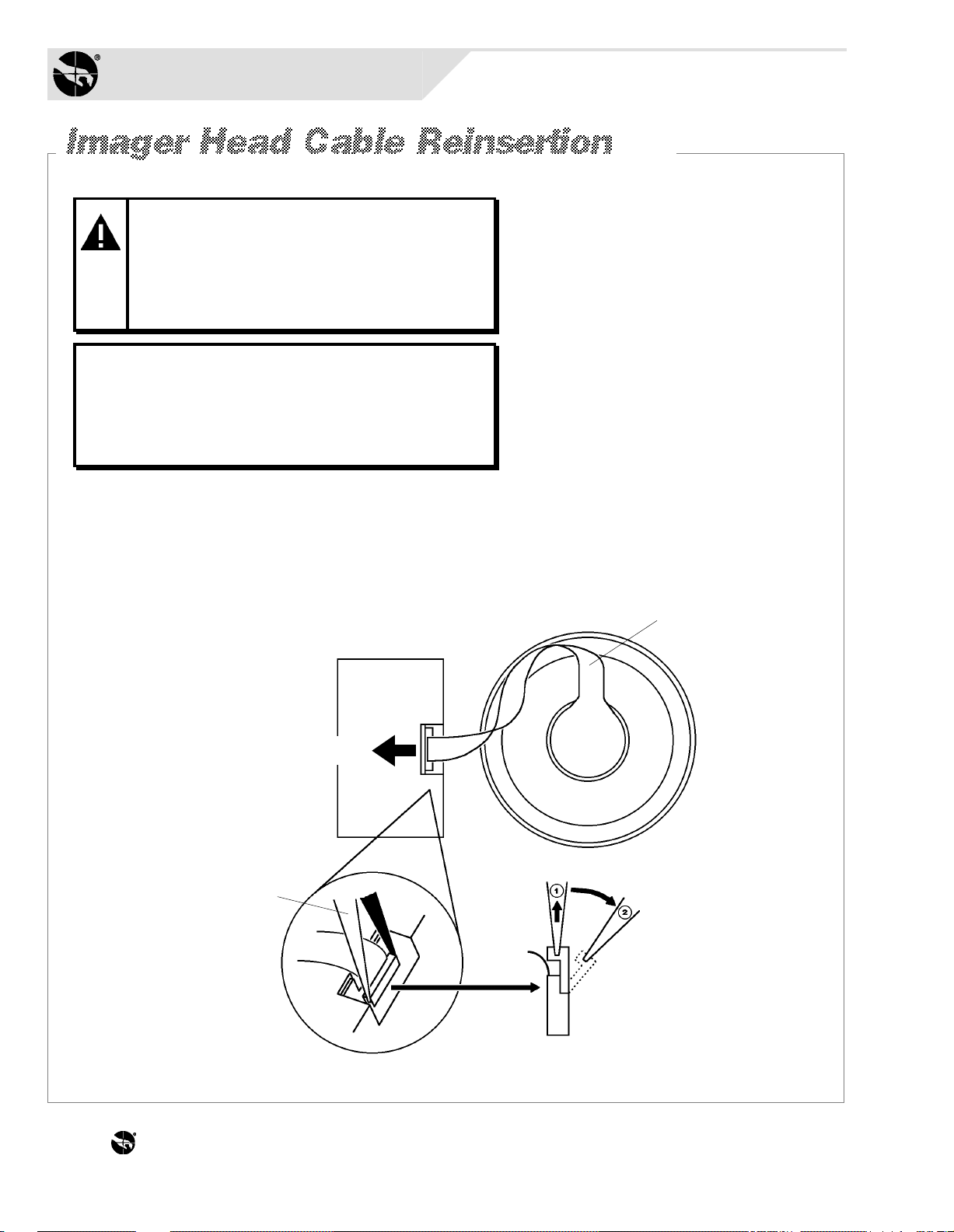
COLOR CAMERAS ONLY!
WARNING: Perform this
procedure ONLY if the imager head
cable was dislodged from the
camera while performing the back
focus adjust- ment procedure or
while replacing the color camera.
IMPORTANT: Note the orientation of
the ribbon cable as it is seated in the
camera. The exposed contacts of the
cable provide the connection between
the camera and the imager head.
Procedure
Using a pair of needle nose pliers, grab the ends of
the camera cable clamp [a] and gently pull it up until
it swings to one side [b]. Next, noting how the ribbon
cable is looped [c], reseat the cable into the
connector. Finally, using the pliers,
push the top of the clamp down to
lock the cable in place.
Color Camera
Ribbon Cable
Cable contacts face this way.
Needle Nose Pliers
[c]
Imager
Head
Lens Body
[b]
[a]
THE WORLD LEADER IN LOSS PREVENTION Q-44
Page 49

Monochrome
Monochrome
Camera Options:
1/2" CCD EIA, 60Hz
2003-0026-01
1/2" CCD CCIR, 50Hz
2003-0026-02
NOTE: Monochrome
camera uses cable PN
0650-0666-01. Color
camera has cable
permanently attached
to the PCI board.
Camera Lens*Camera Lens*
Camera
J1 J3
J2
P6 P1 J2 J3 J4
J5
Clock-Spring
Ribbon Cable Assy.
0650-0623-01
Color
Camera
1/2" CCD NTSC, 60Hz
2003-0027-01
1/2" CCD PAL, 50Hz
2003-0027-02
*
Outdoor Lens Options:
(Monochrome/Color)
1/2" F1.2, 8-80mm
2004-0051-03
1/2" F1.8, 12-120mm
2004-0051-04
DC OUTPUT
P2
5606-0002-02
P5
Power Supply
AC INPUT
AC/DATA FROM
INDOOR J-BOX OR
OIB*, PAGE 48.
Receives female 7-pin
compression-type
connector
2109-0254-06
JP4
JP2 JP3
JP1 JP2
P4
P3
ALARM INPUT
Receives female 8-pin
compression-type
connector
2109-0254-07
P2
AUX. OUTPUT
Receives female
6-pin connector
2109-0108-05
P1
EXT. SYNC
Receives female 2-pin
compression-type
connector
2109-0254-01
P3
J1
VIDEO OUTPUT
TO INDOOR
MONITOR OR
OIB*, PAGE 48.
BNC Connector
p/n 2112-0009-01
*Outdoor Interface Board (outdoor version only).
SENSORVISION SpeedDome
Q-45
Page 50

Sensormatic
SENSORVISION SYSTEMS
(A4)
(G/L In)
A. Gnd.
+12Vdc In
AGC (A6)
+12Vdc In
(BLC) (A7)
12Vdc Gnd.
+12Vdc Gnd.
123456789
J1
123456789
J2
Color CameraMonochrome Camera
Video (Lo) Gnd.
Video (Hi) Signal
123456789
P6
Cam. Gnd.
Vert. Sync.
Hor. Sync.
Cam. +12Vdc
B0B1B2B3B4
(A3)
ALC (A5)
Video Out
Video Gnd.
Video Gnd.
1011121314151617181920
10111213141516
B5 (BLC)
D/A 1 (AGC)
D/A 2 (ALC)
10111213141516
A0
(A2)
X (A1)
V-Fine
(Vcc-Comm. VDD)
N.C.
NAGCV
P1
5V-1
Out B
ALC Video
1
J3
N.C.
Channel B
Channel A
(Vcc) +5Vdc
1234567
ALC Gnd.
2
Gnd.
Out A
Out A
(Vcc) +5Vdc
12345
J2
Gnd.
Channel A
Channel B
Out B
7, 8, 8, 10, N.C.
6
Out A
(Vcc) +5Vdc
12345
J3
Gnd.
Channel A
Channel B
Out B
7, 8, 8, 10, N.C.
6
Out A
(Vcc) +5Vdc
12345
J4
Gnd.
Channel B
Channel A
Out B
7, 8, 8, 10, N.C.
6
Cam. Gnd.
Vert. Sync.
Hor. Sync.
Cam. +12Vdc
Video (Lo) Gnd.
Video (Hi) Signal
123456789
P6
THE WORLD LEADER IN LOSS PREVENTION Q-46
B0B1B2B3B4
10111213141516
B5 (BLC)
D/A 1 (AGC)
D/A 2 (ALC)
N.C.
NAGCV
Out B
Channel B
Channel A
(Vcc) +5Vdc
1234567
P1
N.C.
Gnd.
Out A
Out A
(Vcc) +5Vdc
12345
J2
Gnd.
Channel A
Channel B
Out B
7, 8, 8, 10, N.C.
6
Out A
(Vcc) +5Vdc
12345
J3
Gnd.
Channel A
Channel B
Out B
7, 8, 8, 10, N.C.
6
Out A
(Vcc) +5Vdc
12345
J4
Gnd.
Channel B
Channel A
Out B
7, 8, 8, 10, N.C.
6
Page 51

12345
P6
6
J5
JP4
123
P2
Gnd.
+5Vdc
+12Vdc
Power
Supply
AC
AC
(E) Gnd.
123P51
123456789
Gnd.
TXD
RXD
Reset
Spare
+12Vdc
Gnd.
+12Vdc
123456789
JP2
+5Vdc (Vcc)
JP1
Vert. Sync.
Horz. Sync.
CLR
N.C.
TX A1
RX A1
1
2
111214151819222326273031343538394243464749
+12Vdc
+5Vdc (Vcc)
Address Line 0
Address Line 1
Address Line 10
2
111214151819222326273031343538394243464749
101112
Camera Gnd.
Video (Lo) Gnd.
Camera +12Vdc
Video (Hi) Signal
Gnd.
+12Vdc
Vert. Sync.
Composite/H.D.
101112131415161718
Address Line 2
Address Line 11
Address Line 12
Video (Lo) Gnd.
Video (Hi) Signal
Address Line 3
Address Line 4
Address Line 13
Address Line 14
Clock-Spring
Home H
Home Gnd.
Address Line 5
Address Line 6
Address Line 15
Address Line 16
Assy.
Ribbon Cable
Address Line 7
Address Line 8
Address Line 9
Address Line 17
Address Line 18
TTL Line Sync 50/60Hz
50
Gnd.
Ext. Comp. Sync.
3, 4, 5, 6, 7, 8, N.C.
37, 40, 41, 44, 45, 48
9, 10, 13, 16, 17, 20, 21,
24, 25, 28, 29, 32, 33, 36,
50
Out B
Channel B
1234567
P3
1234578
JP3
Data Line 0
+5Vdc (Vcc)
Video (Lo) Gnd.
Video (Hi) Signal
1234578
JP2
N.C.
Channel A
+5Vdc (Vcc)
Alarm 3
Alarm 2
Alarm 1
Data Line 1
Gnd.
Out A
9
111216172023242728293236404347
Reset *
Alarm 0
Data Line 2
Data Line 3
9
111216172023242728293236404347
UNUSED CONNECTIONS
Signals from JP3 to JP2 that are not being
used on the RS422 Interface Board are as
follows:
ME *
Data Line 4
Data Line 5
TXA 0
Data Line 6
RXA 0
Data Line 7
WR *
DMAEND 1 *
DREQ 0 *
DREQ 1 *
41.
42.
44.
MPU Clk
Wait *
Int. *
13.
15.
19.
RD*
REG 2*
RTS 0 *
REG 4 *
Bus Ack. *
Bus Req *
LIR *
Reg 5 *
45.
46.
48.
49.
* Signal is active low.
IOE *
PF *
SCCENBL *
DMAEND 0
*
21.
33.
35.
39.
50
25, 31, 37 N.C.
6, 10, 14, 18, 22, 26, 30, 34, 38 Gnd.
50
1234567
P4
AC
AC
Gnd.
Data In (Lo)
Data Out (Hi)
Data Out (Lo)
INDOOR:
FROM J-BOX.
OUTDOOR:
FROM OIB*,
SEE PAGE 48.
Data In (Hi)
1234567
P3
Gnd.
Gnd.
Alarm 0
Alarm 1
Gnd.
Alarm 2
8
Gnd.
Alarm 3
12345
P2
Gnd.
Out 0 (P0)
Out 1 (P1)
Out 2 (P2)
Out 3 (P3)
6
+12Vdc
J1
ALARM INPUT AUX. OUTPUT INDOOR:
TO MONITOR.
OUTDOOR:
*Outdoor Interface board.
FROM OIB*,
SEE PAGE 48.
1
P1
Video
Ext. Com. In
Ext. Comp. Ref.
SENSORVISION SpeedDome
2
Q-47
Page 52

Sensormatic
SENSORVISION SYSTEMS
FROM J1
RS422 INTERFACE
BOARD
Video
Video Gnd.
TO P4
RS422 INTERFACE
BOARD
J2
AC/DATA FROM
OUTDOOR J-BOX
HEATER STRIP
5305-0003-01
*Inside Outdoor Housing
MAIN
COOLING
FAN
0650-0678-01
E1E1E6E5E1E1E1E1E9E8E7E4E3E2 E1E1
LOW TEMP.
CUT-OUT
THERMOSTAT
COOLING
FANS
0300-0414-01
J3
J1
VIDEO
OUTPUT
BNC
THE WORLD LEADER IN LOSS PREVENTION Q-48
Page 53

Sensormatic Electronics Corporation
500 Northwest 12th Avenue
Deerfield Beach, Florida 33442 U.S.A.
Telephone 305/420-2000
Telefax 305/420-2017
Toll-free 800/241-6678
®
THE WORLD LEADER IN LOSS PREVENTION
© 1994 Sensormatic Electronics Corporation
 Loading...