

Sensor Therm Regulus RD, Regulus RDK, Regulus RDS, Regulus RDSS, Regulus RDKS User Manual
...
PID Program Controller
Regulus RD / RDS / RDK / RDKS / RDKK / RDSS
User Manual

PID Program Controller Regulus RD / RDS / RDK / RDKS / RDKK / RDSS
Content
2
Content
1 General ............................................................................................................................................... 3
1.1 Information to this Manual ......................................................................................................... 3
1.2 CE Conformity ........................................................................................................................... 3
1.3 Limitation of Liability .................................................................................................................. 3
1.4 Terms of Warranty .................................................................................................................... 3
1.5 Copyright ................................................................................................................................... 3
1.6 Explanation of Symbols ............................................................................................................ 4
1.7 Disposal .................................................................................................................................... 4
1.8 Intended Use ............................................................................................................................. 4
1.9 Scope of Delivery ...................................................................................................................... 4
2 Safety .................................................................................................................................................. 5
2.1 General ..................................................................................................................................... 5
2.2 Electrical Connection ................................................................................................................ 5
2.3 Use of a Pyrometer with Laser Targeting Light ........................................................................ 5
2.4 Secure start / Enable Front Panel Start .................................................................................... 5
2.5 Responsibility of the Operators ................................................................................................. 5
3 Electrical Connection........................................................................................................................ 6
3.1 Pin Assignment ......................................................................................................................... 6
3.1.1 Thermocouple Types -K and -S ........................................................................................... 9
3.1.2 Digital Inputs ........................................................................................................................ 9
3.1.3 Digital Outputs ................................................................................................................... 10
3.1.4 Analog Outputs .................................................................................................................. 11
4 Commissioning ............................................................................................................................... 11
4.1 Operation Modes .................................................................................................................... 11
5 SensorTools Software .................................................................................................................... 12
5.1 Installation ............................................................................................................................... 12
1.1 Program Start .......................................................................................................................... 12
5.1.1 Connecting the Regulus .................................................................................................... 12
5.2 General Settings ..................................................................................................................... 13
5.2.1 Select / Combine Measuring Devices ................................................................................ 13
5.2.2 Pyrometer Alignment ......................................................................................................... 15
5.2.3 Device Configuration ......................................................................................................... 15
5.2.4 Start a Control Process in Manual Mode ........................................................................... 19
5.2.5 Create Program Sequences .............................................................................................. 21
5.3 Starting a Program .................................................................................................................. 24
5.4 Graphical Display / Data Recording ........................................................................................ 25
5.4.1 Data Playback .................................................................................................................... 27
5.5 Communication / Options ........................................................................................................ 28
5.6 Spot Size Calculator ............................................................................................................... 28
6 Device Handling .............................................................................................................................. 29
6.1 Menu Settings ......................................................................................................................... 30
6.1.1 Status Messages / Error Codes ......................................................................................... 32
7 Technical Data ................................................................................................................................. 33
8 Communication via Serial Interface / Interface Commands ....................................................... 34
Index ......................................................................................................................................................... 38

PID Program Controller Regulus RD / RDS / RDK / RDKS / RDKK / RDSS
General
3
1 General
1.1 Information to this Manual
This manual enables the safe and efficient use with the device. The manual is part of the instrument and
has to be kept in a location where users of the controller always have access to.
Read this manual carefully before operating. For secure working all security notes and operation procedures in this manual has to be followed.
Additionally the local accident prevention regulations and common safety regulations of the instruments’
operational area are valid.
The descriptions may differ from the current delivery status, since the pyrometer is continuously developed. Illustrations in this manual are for basic understanding and can differ from the actual construction.
1.2 CE Conformity
The product conforms to the following standards:
CE conformity: DIN EN 61326-1 (electromagnetic compatibility)
RoHS: 2011/65/EU
1.3 Limitation of Liability
All information and notes in this manual are made under consideration of valid standards and rules,
state of technology and our expert knowledge for many years.
The producer assume no liability for damages due to:
Non-observance of this manual
Usage out of intended use
Assignment of unskilled personnel
Unauthorized modifications
Technical modifications
Usage of spare parts not approved
The responsibilities of the delivery contract are valid as well as our general terms and conditions and
terms of delivery and the valid statutory rule at date of the conclusion of contract.
1.4 Terms of Warranty
A warranty period is 24 months from date of shipment form the Sensortherm facility. The seller will repair or replace the device at its own discretion. Further claims of the buyer against the seller or its
agents are excluded, especially claims for damages that are not incurred in the delivery itself. This shall
not apply in cases of intent, gross negligence, or the absence of assured properties. Damage or misuse
of the product will be determined and void the warranty coverage. Repairs paid by the customer will include a 180 days warranty from date of shipment. Transportation costs are to be paid by the customer.
Any claims for damage caused by misuse, neglect or tampering with the sensor are excluded.
1.5 Copyright
This manual is protected by copyrights and are intended solely for internal purposes.
It is not permitted to transfer these instructions to third parties, duplication in any kind and form - including excerpts - as well as recovery and / or notification of contents without written permission of the manufacturer, except are internal purposes.
Contraventions are liable for damages. All other rights reserved.

PID Program Controller Regulus RD / RDS / RDK / RDKS / RDKK / RDSS
General
4
1.6 Explanation of Symbols
The following symbols are used in this manual for restrictions, preventive measures and security notes.
Please pay attention to this symbols for safety reasons.
WARNING: This combination of symbol and signal word indicates a potentially dangerous
situation that can lead to death or serious injury if not avoided.
CAUTION: This combination of symbol and signal word indicates a potentially dangerous
situation that can result in minor or moderate injury if not avoided.
CAUTION, LASER RADIATION: This combination of laser radiation symbol and signal
word indicates the dangers of a laser targeting light.
NOTE: This combination of symbol and signal word indicates a potentially hazardous situation that can lead to property and environmental damage if not avoided.
INFO: This symbol indicates useful tips, recommendations and information for efficient and
trouble free operation.
1.7 Disposal
Dispose of the product properly when it is no longer usable: pyrometers include electrical and electronic
waste and have to be recycled or disposed environmentally friendly or to send to the manufacturer for
disposal.
1.8 Intended Use
The Regulus RD is a programmable PID temperature controller in table housing. It is optimized for use
with one or two Sensortherm pyrometers as temperature sensor. A second pyrometer can be used for a
second measurement point or to enlarge the overall temperature range when using 2 different ranges.
Types RDS and RDK are additionally equipped with a connection of a thermocouple probe type S or K
(Pt10Rh-Pt, temperature range 0-1750°C or NiCr-Ni, temperature range 0-1300°C), types RDSK, RDKK
or RDSS with 2 thermocouples. Selecting a pyrometer and a temperature probe with different temperature ranges enables e.g. operation of temperature recording with a pyrometer after temperature probe
recording. This enables a temperature control with a very long temperature range.
Operating the Regulus with a temperature sensor of other manufacturers is only possible via the analog
4-20 mA input.
1.9 Scope of Delivery
Regulus program controller in table housing
4 plug connectors for sensors and electrical connections, inputs/outputs and 2 for relays contacts, 1
USB cable
Software SensorTools
Info: Connection cables are not included in scope of delivery and have to be ordered separately.

PID Program Controller Regulus RD / RDS / RDK / RDKS / RDKK / RDSS
Safety
5
2 Safety
2.1 General
Any person who is tasked to carry out work with the device must have read and understood the operating instructions before beginning. Operation and maintenance of the system may only be performed by
trained personnel.
2.2 Electrical Connection
When connecting or when working on the mains voltage, the general safety guidelines are observed,
e.g. when connecting power transformers. Supply voltage can be lethal when touching. Improper installation can cause serious injury or physical damage. Only qualified personnel are allowed to work with
mains voltage.
2.3 Use of a Pyrometer with Laser Targeting Light
For easy alignment, the pyrometers may be equipped with a laser targeting light, laser class 2 (according to IEC 60825-1-3-4) and has a sticker shown on the right. The laser emits a visible red light with a
maximum power of < 1 mW and a wavelength around 650 nm.
Safety precautions:
Never look into the direct or reflected laser beam.
Do not point the laser to anyone.
If laser radiation hits the eye, the eyes must be intentional-
ly closed and the head immediately moved out of the
beam.
2.4 Secure start / Enable Front Panel Start
In factory settings the device is set to secure start (“Enable front panel start”). This means the “controller
start” function of the Regulus can only be activated if an additional push button (must also be connect-
ed) is pressed. The function is helpful to prevent an accidentally controller start after changing a setting.
The button has to be connected to one of the digital inputs and activated via software menu (digital inputs). Deactivation is possible but not recommended (see 3.1 Pin Assignment).
2.5 Responsibility of the Operators
If the device is used in the commercial sector the operator is subject to the legal responsibilities for
workplace safety.
In addition to the safety instructions in this manual follow the regulations of safety, accident prevention
and environmental protection.
Laser
beam
direction
Laser warning label
on the device

PID Program Controller Regulus RD / RDS / RDK / RDKS / RDKK / RDSS
Electrical Connection
6
3 Electrical Connection
3.1 Pin Assignment
*) Note connector code: All connectors are coded (red plastic pins) to prevent accidentally inter-
change with other connectors.
Plug Connectors (Manufacturer Phönix Contact)
X1 to X4
Printed-circuit board connector type MC 1,5/12-STF-3,8 Ref.-No. 18 27 800
Cable housing type KGG-MC 1,5/12 Ref.-No. 18 34 440
X5 to X6
Printed-circuit board connector type MSTB 2,5/6-STF Ref.-No. 17 86 873
Cable housing type KGG-MSTB 2,5/6 Ref.-No. 18 03 905
Connectors X1 (Sensortherm pyrometer / external Sensor A) and
X2 (Sensortherm pyrometer / external Sensor B):
Pins
X1
Pins
X2
Function
Cable colors
Sensortherm
pyrometers
1
13
+24 V power supply for pyrometer / external sensor A or B
White
2
14
0 V power supply for pyrometer / external sensor A or B (GND1)
Brown
3
15
+I Analog input (4-20 mA) from sensor / pyrometer
Green
4
16
–I Analog input (4-20 mA) from sensor / pyrometer (GND1)
Yellow
5
17
Not connected
(Grey)
6
18
Not connected
(Pink)
7
19
Shield
Orange *)
8
20
Ground for digital interface RS232/RS485 to external sensor A
(GND1)
Red
9
21
TxD/D+/A for RS232/RS485 to external sensor A or B
Black
10
22
RxD/D-/B for RS232/RS485 to external sensor A or B
Violet
11
23
TxD/D+/A for RS232/RS485 to external sensor A or B
Grey-pink
12
24
RxD/D-/B for RS232/RS485 to external sensor A or B
Red-blue
*) Shield connection of a Sensortherm pyrometer: Only connect the pyrometer to system ground,
the orange shield cable is not connected to the Regulus to prevent ground loops and stray electric
currents.
X8: USB to PC
External sensor X1
External sensor X2
X7: RS232
X9: 24 V power supply
Ground
X10+11: Thermocouple connectors
X5+6: Relays outputs
X3+4: Digital inputs /
control output
Pin 13...........24
Pins 1...........12
Pin 37...........48
Pin 25...........36
Pin 55....60
Pin 49....54
Connector codes *)

PID Program Controller Regulus RD / RDS / RDK / RDKS / RDKK / RDSS
Electrical Connection
7
Regulus
25
...
30
45
>10 kOhm
0 V
+24 V
Input A-F
Switch or push
button, see 3.1.2
Digital Inputs
0 V
+24 V
44 *
)
31 *)
Regulus
34
35
36
Internal resistance
0–5 V
0–10 V
V
A
48
Galvanically isolated
from the power supply
0–20 mA
4–20 mA
Setpoint setting
via external
voltage 0–10 V
2 kΩ
Regulus
31
32
33
Internal resistance
40 kΩ
0 V
+10 V reference voltage
(only devices up to SN 1426)
Setpoint
setting via
potentiometer
Voltage
supply
from SN 1427:
+10 V externally
Connector X3 – Digital Inputs / External Setpoint Settings/ Control Output
Pin
Function
25
+ Digital input A
26
+ Digital input B
27
+ Digital input C
28
+ Digital input D
29
+ Digital input E
30
+ Digital input F
The inputs are activated with +24 V (can be taken from the power supply or connected externally).
*) Devices up to serial number 1426, these 24 V are available at pin 44
*) Devices up to serial number 1426, these 24 V are available at pin 31
When using an external voltage, 0 V (ground power supply, Pin 45) must be used as a reference
point.
44 *)
Up to SN 1426: 24 V (parallel to power supply connector X9) for digital inputs
31 *)
From SN 1427: 24 V (parallel to power supply connector X9) for digital inputs
NOTE to “enable front panel start”:
One digital input can be selected for the function “Enable front panel start” (see settings in 3.1.2
Digital Inputs and Software 5.4 Device configuration). This security function avoids the
accidentally start of the controller due to an additional push button which has to be pressed to-
gether with the “Start” button on the controller. A permanent connection of +24 V (pin 31 or 44)
to the desired output deactivates the function (on your own risk, not recommended).
31
Only devices up to SN 1426:
+10 V reference voltage output
32
0–10 V analog input for external control of the reference
value with potentiometer *
33
Ground for 0–10 V analog input
for ext. control of the reference
value with potentiometer
(GND1)
Note: External setpoint setting with external voltage or potentiometer: In manual mode the reference value can be adjusted via external voltage 0–10 V.
For devices up to serial number 1426, this voltage can e.g. can be taken from the 10 V reference
voltage output (pin 31) and a 2 kOhm potentiometer (as a voltage divider to pins 31-33, the internal
resistance of the input is 40 kOhm).
From serial number 1427 this connection has 24 V for use with the digital inputs, therefore a 10 V
reference voltage must be provided externally.
34
0–20 mA or 4–20 mA
analog control output
35
0–5 V or 0–10 V
analog control output
36
Ground for pin 34 and Pin 35
(GND3)
Outputs selectable via software, see 5.4.

PID Program Controller Regulus RD / RDS / RDK / RDKS / RDKK / RDSS
Electrical Connection
8
Regulus
44
45
Output
Max. 100 mA
0 V
+24 V
100 kΩ
Min. 240 Ω
37
...
43
Regulus
46
47
48
Internal resistance
0–5 V
0–10 V
0–20 mA
4–20 mA
V
A
36
Galvanically isolated
from the power supply
Connector X4 – Digital Outputs / Actual Value Output
Pin
Function
37
+ Output A
38
+ Output B
39
+ Output C
40
+ Output D
41
+ Output E
42
+ Output F
43
+ Output G
44
+24 V power supply (connected parallel to power supply connector X9)
e.g for supply the Regulus when the power supply input should not be used.
45
Ground for power supply (is parallel to the power supply input X9) (GND1)
46
0–20 mA or 4–20 mA
analog actual value output
47
0–5 V or 0–10 V
analog actual value output
48
Ground for pin 46 and pin 47 (GND3)
Outputs selectable via software (see 5.4)
Connectors X5 + X6 – Relays Contacts
X5 and X6 are 4 relay changeover contacts (230 V, 6 A), switched from the outputs A-D.
Pin
Function
X5
49
Center of relays contact RC1
50
RC 1: Pins 49-50 closed at inactive output A
51
RC 1: ins 49-51 closed at active output A
52
Center of relays contact RC2
53
RC 2: Pins 52-53 closed at inactive output B
54
RC 2: Pins 52-54 closed at active output B
X6
55
Center of relays contact RC3
56
RC 3: Pins 55-56 closed at inactive output C
57
RC 3: Pi Pins 55-57 closed at active output C
58
Center of relays contact RC4
59
RC 4: Pins 58-59 closed at inactive output D
60
RC 4: Pins 58-60 closed at active output D
Connector X7 – PC Interface
Pin
Function
2
RS232 PC RxD / RS485 PC D-
3
RS232 PC TxD / RS485 PC D+
5
Ground for interface (GND2)
1 2 RC
49 50 51 52 53 54
3 4 RC
55 56 57 58 59 60

PID Program Controller Regulus RD / RDS / RDK / RDKS / RDKK / RDSS
Electrical Connection
9
3.1.1 Thermocouple Types -K and -S
Please consider the special characteristics of thermocouples if the device is equipped with corresponding connectors. Thermocouple probes are sensitive against temperature variation. Using a Regulus and
a thermocouple with different device temperatures can induce a failure current that results in a temperature display different of the effective temperature.
Always ensure that temperatures of thermocouple and Regulus are the same to achieve a correct temperature result. Wait a certain time after storage or transport the Regulus and a thermocouple in different temperature environments before correct temperature measurement can be achieved. Depending
on the temperature deviations a wait time of 15 to 60 minutes is recommended.
Reduce interference: Induction systems
may cause interferences to the temperature
measured with a thermocouple. To reduce
this, the inductor and the heated object
must be connected to the earth terminal on
the back of the Regulus with a ground wire
of at least 4 mm².
3.1.2 Digital Inputs
The instrument is equipped with 6 digital inputs to operate the instrument
partially extern. Every input can be assigned to one of these functions (see
Software 5.4 Device configuration).
24 V has to be connected either with a push button or switch to an input to
activate its function (see under 3.1 Connector X3).
Start / Stop controller (push button):
Every trigger starts or stops the controller in turn.
Activate controller (switch):
Controller is active as long as input signal is active (24 V to the desired pin).
Emergency stop (switch):
Controller is active if 24 V is set. Without voltage input controller is deactivated, all outputs will be set
to 0 V or 0 mA (safe condition).
Reset error (push button):
Resets the controller in case of a device error. The controller tries to continue operation.
Program step trigger (push button):
In program mode the next program step can be selected.
Enable front panel start (push button): Front panel can only be done with additionally connected
and pressed push button (see 3.1 Pin Assignment Connector X3). The input for this function can
be selected. Stop function on front panel is always executable.
INFO:
Enable front panel start is a security setting to prevent an accidentally controller start.
Deactivation is possible but not recommended.
External program selection (switch), (only inputs A - E): allows the external selection of the manual
mode or a program. The inputs are binary coded, i.e.:
- With a digital input only a program or "Manual" can be activated. With 2 inputs are 3 programs
available, with 3 inputs 7 programs with 4 inputs and 15 programs with 5 inputs, all 26 programs
are available.
At all combinations not listed, "manual" is activated.
Selectable functions:
Induction system
Regulus
Thermocouple
Ground wire min. 4 mm²
Earth terminal
PID Program Controller Regulus RD / RDS / RDK / RDKS / RDKK / RDSS
Electrical Connection
10
Activated
program
Digital Input
(1 = input active)
Program
to activate
Digital Input
(1 = input active)
Activated
program
Digital Input
(1 = input active)
A B C D E A B C D E A B C D E
Manual
0 0 0 0 0 9 1 0 0 1 0
18
0 1 0 0 1 1 1 0 0 0 0
10
0 1 0 1 0
19
1 1 0 0 1 2 0 1 0 0 0
11
1 1 0 1 0
20
0 0 1 0 1 3 1 1 0 0 0
12
0 0 1 1 0
21
1 0 1 0 1 4 0 0 1 0 0
13
1 0 1 1 0
22
0 1 1 0 1 5 1 0 1 0 0
14
0 1 1 1 0
23
1 1 1 0 1 6 0 1 1 0 0
15
1 1 1 1 0
24
0 0 0 1 1 7 1 1 1 0 0
16
0 0 0 0 1
25
1 0 0 1 1 8 0 0 0 1 0
17
1 0 0 0 1
26
0 1 0 1 1
3.1.3 Digital Outputs
The instrument is equipped with 7 digital outputs. Via software every output can be assigned to different functions (see 5.4 Device configuration)
The state of the digital outputs can be adjusted:
NO (normally open): outputs have in active state 24 volts to the pins and
in inactive state 0 V (output max. 100 mA, load min. 300 Ω).
NC (normally closed): outputs have in active state 0 volts to the pins
and in inactive state 24 V (output max. 100 mA, load min. 300 Ω).
Additionally a verification time and hold time in ms can be set (see 5.4 De-
vice configuration):
The verification time defines how long an event is active until the out-
put is activated (for example, the temperature is exceeded).
The hold time defines the time how long the output is hold at least. This feature is useful e.g. if a
PLC error signal requires a signal time of at least 10 ms for a proper recognition.
Selectable Functions
No function
Output is always set to logic 0
Limit value output
If activated a temperature value can be entered from where a contact has to be active (LEDs on the
Regulus show the active state. Additionally outputs A-D are switching the relays). The hysteresis is
the value at how many degree below the limit value the output is switched back. Additionally it can be
selected if the contact is active with exceeding the temperature value or if the contact is inactive (logic
NO or NC).
Message controller active
Output is active if controller is active (in manual mode, program mode or open loop mode).
Message controller ready
Activates the output if a pyrometer or thermocouple is found or the analog input detects a 4 mA signal
(indicates that without connection error the controller is ready to use).
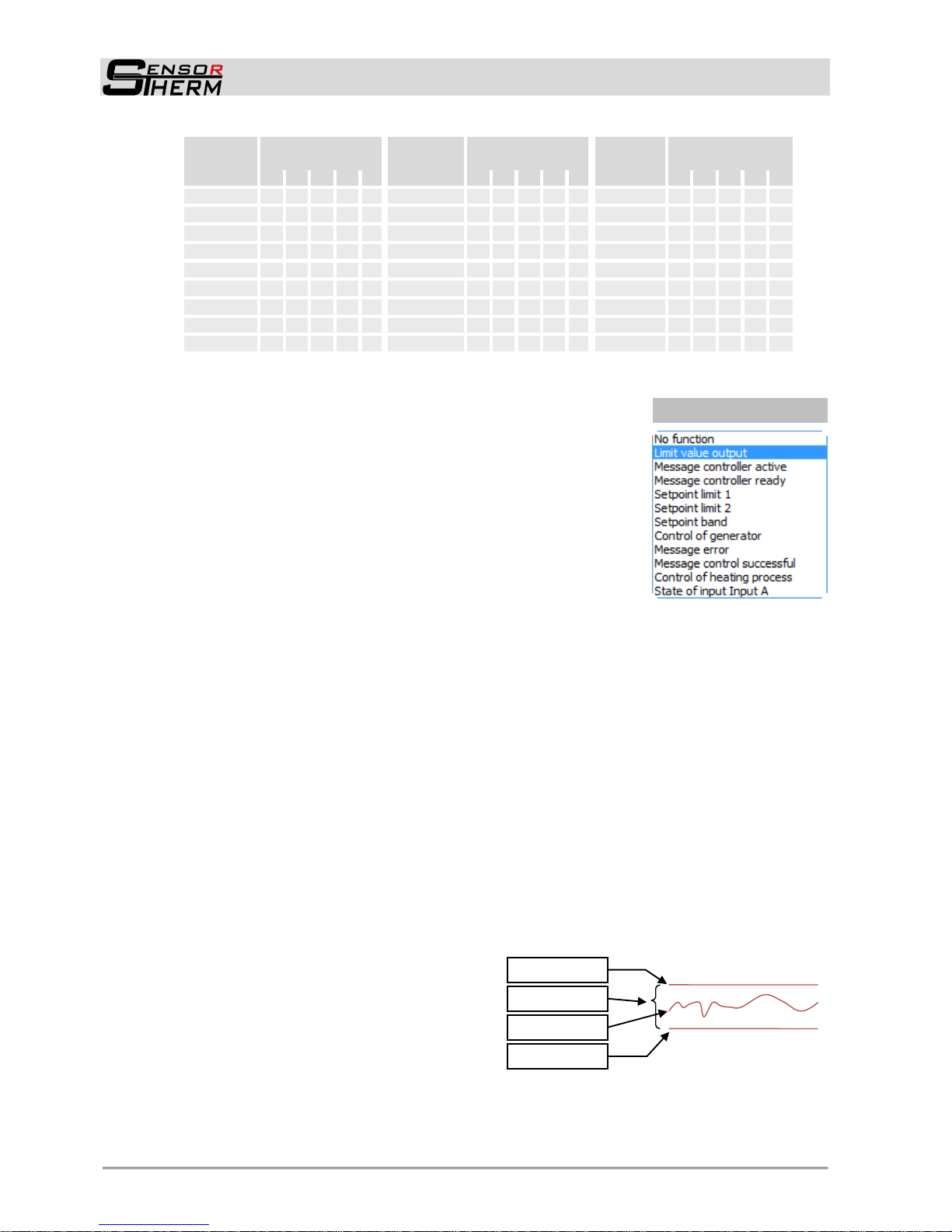
Setpoint limit 1 / Setpoint limit 2
The setpoint limit is a limit temperature above or
below the setpoint temperature that should not
exceeded or to be below. Two setpoints can be
defined. The output is activated if the measured
value exceeds the defined setpoint value. The
output is also activated if the measured value
falls below the defined value. Entry of the setpoint value has to be done relative to the setpoint, positive or negative, e.g. 20°C if the setpoint value is 800°C and the output should be active at
820°C.
Example
Setpoint limit 1
Setpoint band
Setpoint limit 2
Measured value
Selectable functions:

PID Program Controller Regulus RD / RDS / RDK / RDKS / RDKK / RDSS
Commissioning
11
Setpoint band
The setpoint band is composed of the 2 setpoint limits and defines a range within the temperature
has to be. The output is activated if the measured value is outside the defined value.
Control of generator
Allows to enter generator-specific settings for shutdown the generator if the control output falls below
a limit value and reclosing (see under 5.4 Device configuration control of generator).
Message error
Output is active in case of an device error (see 6.2.1 Status Messages / Error codes)
Message control successful
Output is active if control process is finished:
- in manual control: if ramp time and/or hold time is finished
- program mode: if the complete program is executed (with all optional replays)
Note: The output signal is not set if a new controller start is faster than an adjusted verification time.
Control of heating process (belongs to "peak detection“, see under 5.4.2 Create Program Se-
quences Peak detection): Activates the output during the verifying period.
State of input A (not selectable on output G): Detects the state of input A and activates the output
accordingly.
3.1.4 Analog Outputs
2 analog outputs are available:
Control output: According to the requirements the control output can be set to
0-20 mA, 4-20 mA, 0-10 V, 0-5 V or 10 V PWM mode.
Actual value output: According to the requirements the actual value output can be set to
0-20 mA, 4-20 mA, 0-10 V, 0-5 V.
4 Commissioning
4.1 Operation Modes
Different operation modes can be executed with the Regulus (further explanations are to find in the corresponding sections of the software descriptions):
Manual mode
In manual mode an actual value and the required PID parameters are set.
Manual mode can be started directly on the device, per remote push button or via software.
Program controlled
When operating as a program controller, the controller starts predefined program sequences created
via software. Up to 26 programs with a maximum of 256 steps each can be created (limitation: programs + steps max. 990).
A program start can be done via software or directly on the Regulus. Programming itself only can be
done via software SensorTools.
Open loop mode
Starts a control process without feedback from a connected sensor. Anyway, a pyrometer or sensor
can be used to display the current measuring temperature.

PID Program Controller Regulus RD / RDS / RDK / RDKS / RDKK / RDSS
SensorTools Software
12
5 SensorTools Software
5.1 Installation
With the minimum requirements devices can be connect and configured. When capturing or recording
data, the performance is potentially impaired, that is errors or interruptions in data transfer can occur.
With the recommended requirements all software features should be fully available.
Min. system requirement: Pentium IV processor with min. 1.6 GHz and 2 GB RAM
20 MB hard drive capacity for the program
RS232 or RS485 interface or USB2 (use of an RS232 or RS485 to USB interface converter is required)
Recommended: i7 multi-core processor with 3 GHz and 16 GB RAM
20 MB hard drive capacity for the program
RS485 interface
Screen resolution min. 1024x768
Operation system: Windows Vista Ultimate, 7, 8, 8.1, 10
To install, start the setup program. It can be found on the supplied CD or can be downloaded from
sensortherm.de/en/download-section. If the setup program is on USB stick, it should be copied first to
hard disk.
Follow the on-screen instructions
INFO: There are regularly provided software and firmware upgrades available that add functionality or fix bugs. It is recommended always to install the latest software and firmware (available
on the home page in the download area under www.sensortherm.de/en/download-section).
In SensorTools can be checked to a new version, see 5.7).
5.2 Program Start
Starting the software opens
the main window of the program. The Regulus is not connected automatically.
5.2.1 Connecting the Regulus
For successful communication with the Regulus it has to be connected first. The status line on bottom of
the software window shows the current connection status:
Select the computer’s com port the device is connected to. Also a COM port must be
selected when connecting via an USB converter.
Note: Ensure the interface used at the PC is selected on the Regulus. If necessary
change the setting directly at the Regulus, changing via software is not possible (see
6.2 Menu setting <COM Interface > RS).
Press the search button if the com port is unknown. The Regulus will be connected
automatically if the port is found.
Press the connect button to connect the Regulus to the software. All controller settings and programs will be read out and displayed in the software.
The button changes to “Diconnect” when connected. Click to disconnect.
The status line informs about device and connection status.
A detected Regulus shows temperature information, the type of operation mode and a (preset) setpoint.
Follow the instruction to setup the Regulus.
INFO: a Regulus connected to the software has blocked push buttons.
"Keylock" appears when pressing a key.
Select PC
interface
or search
automatically
Connect with
software
Status line
Homepage link

PID Program Controller Regulus RD / RDS / RDK / RDKS / RDKK / RDSS
SensorTools Software
13
Software Window – Overview
5.3 General Settings
5.3.1 Select / Combine Measuring Devices
The connected pyrometer(s) or temperature probes have to be selected and configured be-
fore temperature measurement is successful.
Select connected
measuring devices
Combine multiple
measuring devices
and set as selection
to be used for measurements later
Measurement data
and information field
Operating mode
(manual mode /
program selection))
Direct access to
control parameters in
manual mode
Controller start /stop
Device configuration
Create control programs
Select / combine
measuring devices
Main window
Control window
Graph window for displaying measurement and control data
Time axis settings
Temperature scale
Time axis
(current
time)
Data recording, data
recording settings, data
playback
Information to sample time
and control time
Select display graphs
(right click to change the
color settings of the
graph), activates or deactivates graphs
Control value scale
Measuring temperature or
underflow / overflow of
sensor‘s temperature range
Setpoint temperature in
manual mode or
program selection

PID Program Controller Regulus RD / RDS / RDK / RDKS / RDKK / RDSS
SensorTools Software
14
A Sensortherm pyrometer (digital sampled) is connected via serial interface and the temperature
range is automatically read out.
A Sensortherm pyrometer (analog sampled) is connected via serial interface and analog input, but
the analog output of the pyrometer used as signal transmitter. This connection can be selected if a
very rapid evaluation is necessary which does not work via interface, for example, at long interface
cables or when using high-speed pyrometers.
"Sensor settings" is used to configure pyrometer settings
For analog sampled devices the current output and temperature range must be set. The Regulus
can handle temperature ranges from 0-3300°C, the entered “temperature range” is the range of the
analog output range.
Thermocouples are available depending on the model.
At measurement errors, the temperature curve can be provided with an
offset.
Combine measuring devices:
All connected measuring devices can be combined as a unit and a transfer temperature are defined.
Two measuring devices can measure sequentially, for example, a thermocouple for the lower temperature range and a pyrometer for the higher.
4 combinations are possible (selection A, B, C, D). Then, each selection can then be used for the
measurement process, in program mode even each program can be assigned another combination
(manual mode: see 5.4.1 Start a Control Process in Manual Mode -> “Sensor adjustment”. Program mode: 5.4.2 Create Program Sequences setting field = Measuring device selection).
is used to assign 2 connected measuring devices to a selection:
- Component 1 and 2: each selection will be done by the connected measuring devices. However,
component 1 is always defined by the lower temperature range.
Use the arrow key button to swap the measuring devices.
Example: Two sensors are connected, a NiCrNi thermocouple on X10 with a temperature range 01350°C and a pyrometer connected to “X1” with a temperature range of 350-1800°C.
The bar graph shows the complete temperature range, the handover temperatures of both components and the resulting hysteresis (temperature difference).
- The handover temperature / hysteresis defines the temperature at which the temperature measurement is hand over from one measuring device to another at increasing or decreasing temperature. The difference is the hysteresis.
- Upper measuring limit component 1: handover temperature, where component 1 changes to
component 2 when the temperature is increasing.
- Lower measuring limit component 2: handover temperature, where component 2 changes to
component 1 when the temperature is decreasing.
Note: The handover temperature of component 1 has to be higher than of component. 2
Upper measuring limit component 1
Hysteresis
Selected temperature range component 1
Possible temperature range component 1
Lower measuring limit component 2
Temperature range component 2

PID Program Controller Regulus RD / RDS / RDK / RDKS / RDKK / RDSS
SensorTools Software
15
5.3.2 Pyrometer Alignment
Precondition of a successful control process is a steady
temperature capturing. Align the pyrometer or sensor to an
area where a control process can be influenced (e.g. to a
faster heated border than a centered alignment).
5.4 Device Configuration
Here basic device settings are made.
Miscellaneous settings
- Setpoint deviation: The setpoint deviation is a global parameter that controls the program flow.
The setpoint level is the maximum deviation between actual value and nominal value to consider a
value as controlled successfully and start the next step.
- Range setpoint input: Defines the temperature range for the analog setpoint (possible range between 0 and 3300°C). The function is activated in the parameters control window.
- Key lock: To lock or unlock the key functions on the Regulus.
- None: All functions can be changed using the buttons on the unit.
- Active: The buttons on the unit are disabled.
- Menu lock: activates an input field for a 4-digit PIN code, which enables to protect changing of
parameters (PAR key) on the device. If activated, this code must be entered on the device before parameters with the PAR button can be changed.
Digital output
configuration
Digital input
configuration
Miscellaneous
settings
Analog outputs
configuration
Service functions,
and connection
settings
Example

PID Program Controller Regulus RD / RDS / RDK / RDKS / RDKK / RDSS
SensorTools Software
16
Analog outputs (see 3.1.4)
- Measurement temperature (actual value output) / control output: Select the required output for
the connected device.
- PVM interval (period’s time) (only available if 10 V PWM is selected): Select the value corresponding to your connected device.
- Adaptation: the temperature range span can be scaled down in order to adapt it to specific measurement conditions.
Press the test button
to check the functionality of the
analog outputs.
Moving the slide control will set
values for the selected output.
The “On” button will transmit
the test setting to the controller
output, the Regulus shows the
result.
As notification on the Regulus a
blinking “Testfunction” text ap-
pears.
Digital input configuration (see 3.1.2)
Select the desired function in the list box for each (connected) input.
Digital output configuration (see 0)
Select the desired function in the list box for each (connected) output.
Every output has its corresponding settings in the line beside the output function.
- Setpoint: Values can be entered only if “Limit value output” is selected.
- Hysteresis: Only active if “Limit value output” is selected
- Logic: Sets the general functions of the output. NO: “Normally Open” or NC: “Normally Closed”
- Extended settings: Depending on the selection are either available:
Time settings: A verification time and a hold time can be set:
- Verification time: select “immediately” to activate the output function immediately when hap-
pening. A time between 1 and 65535 ms delays the activation accordingly.
- Hold time: A time can set to remain activated output for a desired time.
- None: signal is active as long as the function is active
- Process start: signal is active up to the next start (of a program or manual start)
- Time value between 1 and 65534 ms: signal is active for the entered time.
Reference: for selecting which measurement temperature to be used for the output control (which
pyrometer or which sensor or sensor combination).
Setting control of generator
Note: This output sets the time settings to 0):
- Control value limit: Defines the limit the control
output should be activated (minimum generator
power, if this cannot controlled continuously down
to 0%). Below the set value the control function is
switched off).
- Pick up verification: specifies the time the controller output must reach the control value limit
without interruption, before the output is activated.
- Drop down verification: specifies the time the controller output must be less the control value limit without interruption, before the output is deactivated.
- Start delay: Delays checking the control value limit at a controller start.
- Output activation by control start: Activates the output directly at the control start without check-
ing the pick-up verification and start delay time.
Settings depending on the
connected
generator
Slide control
Output values
Activate Test
Control output
Test display

PID Program Controller Regulus RD / RDS / RDK / RDKS / RDKK / RDSS
SensorTools Software
17
Setting heating control
The output switches at a detected temperature peak (see in 5.4.2
Peak detection function). Switching back of the output can be de-
layed.
With the Test function digi-
tal inputs and outputs can be checked for errors.
Click on an “Output control” check box to activate the corresponding output. A green LED
symbol signalizes the activation.
Digital inputs are marked with a green LED
symbol if connected and active.
Activation of the outputs will also activate the
LEDs on the Regulus.
As notification on the Regulus a blinking “Testfunction” text appears.
CAUTION! Using the test function will activate the selected outputs.
All connected systems will start working.
Always pay attention to the security instructions of these systems!
Temperature unit
The temperature can be displayed and entered in °C or °F.
(Changing the mode will not change the entered values, no conversion will be done).
Service functions
To back-up, for printing or restore device parameters or create service files for remote diagnosis of problems.
- Create configuration file: A configuration file includes all
device settings made by user. This can be used e.g. to
setup a new pyrometer with the same values and settings
or to save the current status in case of a device replacement.
- Load configuration file: load a previously saved configuration data in the pyrometer.
- Print parameters: Prints the parameters of the currently
connected device.
- Print configuration file: Prints a saved file.
- Factory settings: Resets the device to its factory defaults.
- Create service file: A service file includes all device data
and all software settings made by user. Creating such a file
can be useful if a controller problem can’t be solved and help from our service could be useful.
- Upload service file: Transmitting a (possibly modified) file to the device it was created from.
Serial Interface
For setting the baud rate (not with USB), device address and interface delay (in the case of faulty data transfer).
Note: The serial interface type and the device address can be
changed directly on the Regulus (see 6.2 Menu settings under
<COM Interface>).
Device addresses from 00 to 97 are valid. Addresses 98 and 99 are
with special functions. The global address 99 can be used to communicate with every controller, independent of the set device address. This allows communication with devices with unknown addresses. The address 98 is a group
address used for RS485 devices in bus operation. With this address devices do not answer, useful to
change parameters of all connected devices at the same time.
Output check
Input check
Activate output
Test display
Regulus LEDs

PID Program Controller Regulus RD / RDS / RDK / RDKS / RDKK / RDSS
SensorTools Software
18
Data Collection (buffer mode) (Only available when connected via serial in-
terface. Not with USB, since this always runs with the highest possible speed).
The measurement data transfer from Regulus to the PC can vary depending on the requirements and
computing power. Speed and transferable amount of data are dependent on the baud rate and the
data mode. In the data collection window are shown the amount of measured values determined by
calculation for each baud rate and each mode. When set to "Auto. interval adjustment ", the corresponding values of baud rate selection will be entered automatically in the field on bottom right. When
required, they still can be adjusted manually, for example, if the calculated values still give problems.
USB always works internally with the baud rate 921.6 kBd.
ASCII mode: The Regulus always transfers separate readings to the software and shows
each in the graph as a pixel. In
addition to the transmission of
measured values, also regularly
status values are transmitted
(limit contacts or active laser
targeting light...), so that measured values do not always arrive at the same time interval.
For most applications this
speed is sufficient, a modern
PC can transmit every 5 ms a
value at 921 Kbits.
With buffer mode: Measurement data are temporarily
stored in the internal buffer of
the controller and periodically
transferred to the software in
blocks, additional control information (I/O states, laser targeting active,...) will be transmitted
cyclically. The buffer interval
defines how fast the internal
FIFO buffer of the Regulus is
filled. The shorter the time, the
more data per communication block will be transferred.
An interval time set too fast in relation to the baud rate and computing power leads to buffer overflows, which are represented by vertical bars in the graph. A modern PC reaches intervals of about
0.3 ms at 921 Kbits without buffer overflow, at 57 Kbits intervals of approximately 3.6 ms. If buffer
overflows occur, the interval time can be increased, the baud rate can be increased or unnecessary
programs and background services be stopped. A minor impact also has the reduction of the maximum data records in memory (see under 5.6 Data recording settings).
- Display mode:
- Controller display: In the software window
the actual measured temperature, the setpoint
and the control mode are displayed.
- Sample display: The software settings window, the temperatures of all sensors and actual value and setpoint display. This can be
used to display the temperatures of all measuring instrument combinations.
Active mode
Switching the display in the
measured values and the
info field (control window)
Current setting
(With USB port
always 921.6 kBd)
Open the settings
window
Transmission rate of
the serial interface in
Baud
Automatically take
over values/s
Manually adjust
buffer interval

PID Program Controller Regulus RD / RDS / RDK / RDKS / RDKK / RDSS
SensorTools Software
19
5.4.1 Start a Control Process in Manual Mode
In manual mode, a setpoint temperature and necessary PID
control parameters can be entered directly into the software
or at the Regulus. Starting the process will start to control to
the setpoint temperature with the set parameters. The control process will be hold until is finished manually or automatically if a hold time is entered which runs if the setpoint value
is reached.
Parameters can be changed during a running control process and will be taken over by pressing “Enter” on the key-
board. Invalid values will be automatically corrected to the
next possible value.
Note: all values in this “Control parameters” window can also
be set directly at the Regulus (see 6 Device Handling).
INFO: At control process where the temperature is
approached from a temperature higher than the
setpoint temperature should be optimized selecting
this field. If setpoint temperature is reached from
upper temperature the integration sum of PID control is set to 0. In this case undershooting the setpoint temperature is avoid in the control process.
Control mode : Switching between manual
mode and stored control programs. The mode is displayed once again in the upper display.
Measuring device selection :
To set, which measuring device selection is
used to carry out by the measurement (see
5.3.1 Select / Combine Measuring devices).
General parameters
- Setpoint: Setpoint specification
- Analog setpoint: when activated, the analog input is used to specify the setpoint externally via
voltage input (see under 3, Electrical Connection Connector X3 External Setpoint Settings).
- Ramp time (in 100 ms): The setpoint temperature will be approached by increasing the temperature with a uniform gradient of the temperature within the entered time.
- Hold time: to hold the reached control output value a hold time can be set. Control process is continuing automatically after reaching the setpoint temperature and expiring the hold time.
PID parameters
- Xp: The proportional band represents the reciprocal of the gain of the controller (Entering 0.1-
1000%, 0.1 = highest gain, 1000 = lowest gain).
- Ti: The integral time constant represents a kind of smoothing or delay (Note: Ti is a multiple of the
sampling time. Therefore, changes in the sampling time have an impact on this value).
- Td: The derivative time constant slowdowns the rapid rise to prevent overshooting (Note: Td is a
multiple of the sampling time. Therefore, changes in the sampling time have an impact on this value).
- Sampling time: Select how quick temperature values will be read out of the sensor. Select the parameter depending on the inertia of the heating process (Note: Ti and Td are a multiple of the
sampling time. Therefore, changes in the sampling effect changes in Ti and Td).
Current measuring
temperature, setpoint and control
mode
Select manual mode
Enter required values in the boxes.
Press “Enter” to take
over the values
Start the control
process
AutoTune for automatic detection of Xp
and Ti values
Setpoint entry
Hide rarely used
parameters
Previously determined
measuring devices
selection
Channel selection for
ratio pyrometers

PID Program Controller Regulus RD / RDS / RDK / RDKS / RDKK / RDSS
SensorTools Software
20
Power adjustments
- P-min: The minimum control output power defines the power which is to the control output at least.
- P-max: The maximum control output limits the power to the entered value.
- P-zsc: Limits the control output power as long as the beginning of the sensor’s or pyrometer’s
temperature (zero scale temperature) range is reached. This is useful to avoid a too fast start of a
heating process because the object temperature is out of the pyrometer’s temperature range.
Threshold values (values in this field are not available directly in the parameters menu of the Regu-
lus):
- Setpoint limit 1 and 2: Activates every selected “setpoint limit” output 1 or 2 (see 0 Digital Outputs
and 5.4 Device configuration) if the set temperature is exceeded or falls below. The required temperature has to be set relative to the setpoint temperature (in the control parameter field), not as
absolute value.
- P dynamic: Limits the power, the control output can control suddenly (standard 100%).
AutoTune settings
- The AutoTune target temperature defines the temperature that is used for Xp and Ti determina-
tion. The entry occurs in % and defines the difference between setpoint and actual value (example:
setpoint is 1000°C, the measurement object is cold which means the actual value is the pyrome-
ter’s beginning of temperature range and thus, for example, 500°C, then the target temperature is
750°C at 50% factory setting). Only a value below 100% prevents a temperature exceeding during
P-I-determination and thus a possibly material destruction due to overheating.
- Next start with AutoTune: Starts the AutoTune function prior to the next control start, then immediately the control process starts with the found PI parameters. This also works with an external
control start. The function is only active for one controller start and will be deactivated (unchecked)
with the next control start.
- Controller start always with AutoTune: starts AutoTune prior to every control start, then the con-
trol process directly starts with the found PI parameters (also works with an external controller
start).
The AutoTune function enables to detect automatically useful values for the proportional
band Xp and integral time constant Ti. The function tries to find the values Xp and Ti without overshooting the setpoint temperature.
NOTE:
AutoTune usually results in only a guide, their further optimization is necessary then.
Starting the Controller
Press Start to start the control process. Pressing the start button at
the Regulus will also start the procedure in the software.
Press stop to quit the process.
Press the red record button to store temperature and control values to the PC’s hard disc.
Note: Recording can be started simultaneously with controller start if corresponding setting is made
(see Data recording settings under 5.6: under “automatic recording by active control” and if required
“automatic end of recording by inactive control”).

PID Program Controller Regulus RD / RDS / RDK / RDKS / RDKK / RDSS
SensorTools Software
21
5.4.2 Create Program Sequences
Select the Programs tab to reach the window for creating or changing program sequences, save on the
computer and transmit them to the Regulus.
Overview
General Program Structure
26 programs can be generated, each with up to 255 program steps (limitation: the sum of the programs and steps
can not exceed 990).
All programs together will be called program list.
Create a New Program
The name appears in the list box shows the program parameters
New creates a new empty program with a name
(Note: only 16 characters can be displayed in the “control mode”
field (see 5.5))
Rename the current program
Saves the current program to a file
Delete: Removes the current program
Adds a stored program to the program list
Replace overwrites the current program with a stored one
Save: Saves the
complete program list
to a file.
Load: Loads a complete program list in
this window.
Save or load all
programs (program
list) to or from a data
storage medium
Transmit or read all
programs (program
list) to or from
Regulus
Program steps to be
executed
General program
parameters
Edit programs
Edit program steps:
Select sensor
Import of manual
values
New line
Delete line
Graphic chart of
current program
Transfer: Transfers all
programs (the program list) to Regulus.
Read: Transfers the
program list from
Regulus in the software.
Program A
Program steps
Program B
Program steps
Program C …
Program steps
Program list

PID Program Controller Regulus RD / RDS / RDK / RDKS / RDKK / RDSS
SensorTools Software
22
General Program Parameters
Settings in this field are only valid for the current program.
INFO: A control process where the temperature is approached from a temperature higher than
the setpoint temperature, the controller cannot control active, as the attainment of the temperature depends on the cooling rate of the material. If the setpoint temperature in this case is
reached from the higher temperature, the sum value of PID control is set to 0 to avoid an undershooting of the setpoint temperature as good as possible.
Start delay: The program start can be delayed (0 to 65.535 s)
Power till zero scale: Limits the control output power as long as the beginning of the sensor’s tem-
perature range is reached. This is useful to avoid a too fast start of a heating process because the
object temperature is out of the pyrometer’s temperature range.
Sampling time: Select how quick temperature values will be read out of the sensor. Select the pa-
rameter depending on the inertia of the heating process (Note: Ti and Td are a multiple of the sampling time. Therefore, changes in the sampling effect changes in Ti and Td).
P dynamic: Limits the power which the control output can control suddenly (standard 100%).
Minute base: Changes the time unit of ramp time and hold time to minutes instead of 100 ms base.
Open loop mode: Starts a control process without feedback. A pyrometer or sensor is not required in
this mode, a selected sensor in the sensor tab has no influence (see 5.3.1 Select measuring devices). Anyway the sensor or pyrometer can be used to check the object temperature.
In open loop mode a value for the controller output power (P-Set) has to be set to the program steps.
Cycles: To select how often a program shall start again if finished (1 - 65535 and infinity can be se-
lected).
Gradient ramp: A gradient in degree per second can be entered instead of ramp time values.
Peak detection: Automatically detects a defined positive or neg-
ative temperature peak to automatically go to the next program
step. Additionally, the digital output (see 0) “Control of heating
process” can be activated at detected temperature peak. It is activated when the program is running and during the verify time. At
a detected temperature peak the output is set to inactive (where
required with a delay if an appropriate hold time is set).
Peak detection settings:
- Verify time: Time from program start, within
the temperature peak should to be recognized
(up to firmware 2015_10: entry 0.001–65.535 s;
from firmware 2015_11: entry 0.1–6553.5 s). If
no temperature peak is detected within the verify time, the program will be canceled. If a temperature peak is detected, the next program
step is executed and the verify time has no
function anymore.
- Activation difference: Specifies the temperature where the peak detection starts to operate.
The value is entered relative (by difference) to
the setpoint.
- Detection difference: Specifies the sudden
temperature difference to the setpoint value
that identifies the difference as peak.
- Program step: defines the current program
step, the peak detection is to be executed.
- Peak form: defines whether the peak detection should work with sloping (negative) or rising temperatures (positive) or in both directions.
Setpoint
Actual temperature
Activation
threshold
Activation
difference
Detection
activated
No detection
Detection
difference
Next
program step
Negative peak
Positive peak
Output contact „Control of heating process“
1
0
Program step

PID Program Controller Regulus RD / RDS / RDK / RDKS / RDKK / RDSS
SensorTools Software
23
Entering Values for a Programmed Process
Setpoint: Setpoint specification
Ramp time (in 100 ms): The setpoint temperature will be approached by increasing the temperature
with a uniform gradient of the temperature within the entered time (0.0 s is off). During ramp time the
temperature is controlled continuously. A maximum ramp time of 655.35 °C/sec is possible.
Hold time: to hold the reached control output value a hold time can be set. Control process is contin-
uing automatically after reaching the setpoint temperature and expiring the hold time. During hold
time the temperature is not controlled, only hold.
Xp: The proportional band represents the reciprocal of the gain of the controller (Entering 0.1-1000%,
0.1 = highest gain, 1000 = lowest gain).
Ti: The integral time constant represents a kind of smoothing or delay (Note: Ti is a multiple of the
sampling time. Therefore, changes in the sampling time have an impact on this value).
Td: The derivative time constant slowdowns the rapid rise to prevent overshooting (Note: Td is a
multiple of the sampling time. Therefore, changes in the sampling time have an impact on this value).
P-min: The minimum control output power defines the power, which is to the control output at least.
P-max: The maximum control output limits the power to the entered value.
P-Set (only available in open loop mode): a value for the controller output power has to be set.
Ɛ1 / Ɛ2: To enter the material properties (emissivity or emissivity slope for ratio pyrometer) for py-
rometers connected to Component 1 or 2 (under measuring device selection for ratio
pyrometers, separate measuring channels can be selected).
Limit 1 and 2: If “setpoint limit 1” or “setpoint limit 2” is select as digital output (see 0 Digital Outputs
and 5.4 Device Configuration) the corresponding temperature can be set for every
program step.
Measuring device selection : To
set, which measuring device selection is
used to carry out by the measurement (see
5.3.1 Select / Combine measuring devices).
Table handling:
- Adds a program step behind the current line. Current values will be taken over.
- Imports values from the manual entry field in the row
- Deletes the line
Transfer: Transfers all programs (the program list) to Regulus.
Read: Transfers the program list from Regulus into the software.
Program steps
Graphic chart of
current program flow
Program parameters
Previously determined
measuring devices
selection
Channel selection for
ratio pyrometers

PID Program Controller Regulus RD / RDS / RDK / RDKS / RDKK / RDSS
SensorTools Software
24
5.5 Starting a Program
Program start will be done via the Regulus or in the
control window of the software.
Select a program to be executed.
Software: in the control window.
Regulus: With the PAR button select the (second)
menu point <Control Mode> and with the arrow keys
the program. Take over the program with “Enter”.
Press “PAR” repeated (or wait 60 s) until measuring
temperature is displayed, now the program can be
started with the start button.
Press the start button in the control window to start the control process.
Pressing the start button at the Regulus or external will also start the
procedure in the software.
Press stop to quit the process.
Graphic Chart of Current Program Flow
The graphic chart visualizes the planned control process. Example with values of the last screenshots:
Process:
Pressing “start” via software, at the Regulus or external will start a program or the manual mode, de-
pending on the selection.
A program stops automatically after the last step or after the last cycle if several cycles are set.
Pressing the stop button interrupts the control process. A restart begins with step 1.
A program step is reached successfully if the measuring tem-
perature is within the range near the setpoint, defined in the
device configuration (section 5.4, Device Configuration under
“Setpoint deviation”. Thereby the next program step is proceed.
Start
delay of
5 s
Step 1:
Actual value
of 700°C with
a hold time of
5 s
Step 2:
Actual value of
1000°C with a
ramp time of 5 s
and a hold time of
5 s
Step 3:
Actual value
of 1200°C
with a hold
time of 5 s
Step 4:
Actual
value of
1400°C
with a 7 s
ramp
Step 5:
Actual value
of 1400°C
controlled for
8 s
Step 6:
Act. value
of 100°C
(depicted
time is
estimated)
Step 7:
Actual value
of 500°C with
5 s hold time
Setpoint
deviation
Measured
value
Current measuring
temperature
Select a program
Current setpoint
Selected program

PID Program Controller Regulus RD / RDS / RDK / RDKS / RDKK / RDSS
SensorTools Software
25
5.6 Graphical Display / Data Recording
The graph window is used for monitoring the sensor temperature(s) and the control process. It shows
measuring information once the Regulus and a sensor is connected.
The colors in the graph show the measured temperature (the temperature, which is responsible for the
control process and can be seen on the device display or in the control window), the setpoint tempera-
ture (only if controller is started), the temperatures of the sensor combinations (see 5.3.1) and the power of the control value output.
The graph window in the main window shows the temperature profile in time.
The time axis (horizontal axis labeling of the X-axis) indicates the current time.
Scale X-Axis allows to set the time at which the graphs window is filled with measured values. If the
time is changed, the graph rebuilds itself from the window center.
- rebuilds the graph from the left.
- Sets a recording time to 0 (has only effect in the playback file)
Scale the graph: Beginning and end of temperature scale (left) and control out-
put (right) scale can be adjusted to represent the relevant area reasonable
- Scale per mouse click: With the green arrows of the upper and lower scale
range is changed
- Scale per entry: The upper and lower temperature can be entered via the
keyboard.
- Scale with mouse drag: With click, hold and drag on the gray arrows, the
start and end or the entire area can be moved.
- Automatic scale: automatically adjusts the scale (+10°C above the maximum value and -10°C below the minimum value):
- reads out the Regulus temperature range (0-3300°C)
- selects the range from all selected display graphs and always the
highest measured value.
Information field
- RD-1365 in the example on the right shows Regulus model and serial number.
- The sampling time T-Sample Shows the time between the last two received
measured values.
- The control time T-Contr. shows the time a control process is running already.
Select display graphs:
- Depending on the device type, different graphs can be displayed or hidden; the color can be
changed by right-clicking on a color field.
Select display graphs (right click
to change the color settings of the
graph), activates or deactivates
graphs
Time axis settings
Measured temp.
numerical / graphical
Direct access to
control parameters in
manual mode / Display the parameters
of each step in program mode
Temperature scale
Main window
Control window
Information to sample time and
control time
Data recording, data recording
settings, data playback
Controller start /stop
Operating mode
(manual mode /
program selection)
Current time
Control value scale
Scale per
mouse click
Scale with
mouse drag
Scale per
entry
Automatic
scale
Adapt to
pyrometer’s
temp. range

PID Program Controller Regulus RD / RDS / RDK / RDKS / RDKK / RDSS
SensorTools Software
26
The transferred measured value data can be recorded on hard disk for subsequent analysis.
Click the recording button to start and stop recording, the button flashes when recording is active
( ), Pause interrupts the recording. When recording is active, a red reference text is displayed above the graphics window (pyrometer model-serial number: write file pyrometer model-serial
niumber_sequential number.r2b).
Data recording settings
- File options (The selected option is displayed in the main
window above the graph with: pyrometer model and serial
number, file name and a running number):
- Overwrite file (Overwrite mode): Overrides the same
file with each new recording.
- Create new file (Fileindex mode) creates a separate
file for each recording.
- Append data (Append mode): With each new recording, the new values are appended to the previous one
- Storage interval: Writes a reading in the file with the set
storage interval. At 0.0 s, the storage is done as fast as
possible (depending on baud rate and buffer mode).
- Automatic recording by:
- Active control (shows only effect when equipped with a
PID controller): Starts recording automatically when a
controller-start takes place (also at an external start).
- Active I/O port: Starts recording when a digital input or
output is active. The port selection will be done at I/O
port at the bottom of the window.
- Back-time recording: If the record button is pushed (or recording is activated by active I/O port
and setting "automatic recording by active I/O port" is checked), values are stored retroactively for
the entered time but only as many, as entered under "Maximum data sets in memory".
- Automatic end of recording by:
- Inactive control (shows only effect when equipped with a PID controller): Stops recording when
a control process is stopped (even with automatic or external stop, error, etc.).
- Inactive I/O port: Stops recording when a digital input or output is disabled.
- Post-record of recording: recording can be continued for a while if control process is stopped,
e.g. to record a cool down process
- Maximum data sets in memory: Number of measurement data sets (consists of measuring temperature, emissivity, device temperature, setpoint-value...), the program maximum keeps in the
memory to display this on back-time recording or in the playback window (MEM button), (data recording, however, is only limited by disk size).
- As I/O port an digital input as well as output can be selected
INFO: If an output is used, the assigned function can be used for controlling the auto-
matic recording, for example for automatic recording when a certain temperature is exceeded (limit switch activated).

PID Program Controller Regulus RD / RDS / RDK / RDKS / RDKK / RDSS
SensorTools Software
27
5.6.1 Data Playback
Press the playback button in the main windows to open a playback window and show the last
measured values.
Press the “Load data” button to open a saved file and display in the playback win-
dow. To compare several measurement curves, you can select several files, each file will be opened
in a separate window. The SensorTools Viewer can also be opened by double-clicking on a data file.
Press “Copy data file” to copy one or separate files into another folder. Select the
files you want to copy, the original files are not removed. In the next window a folder can be selected
where files should be copied. Then a file name is suggested containing date and time. All selected
files will be numbered in sequence with the chosen name.
Hold down the mouse button and drag a selection to view a detail. To select details, a selection can be
dragged with the mouse. To move the view, on the temperature or time scale the view can be moved
with the mouse (middle of the scale) or the upper and lower limits are changed (upper or lower end of
the scale).
Color settings of graphs
(same as in main windows)
Recorded data
Current mouse position
File information of the vertical mouse
position
View the complete file
If zoomed in: jump to beginning or end or
to next image section
Save current selection
Export the current selection to a csv file
(e.g. to open in Excel)
Print current selection
Select and load file for viewing

PID Program Controller Regulus RD / RDS / RDK / RDKS / RDKK / RDSS
SensorTools Software
28
5.7 Communication / Options
Sprache / Language: Selects between German and English user interface.
Print configuration file has the same function as in the device configuration under "service func-
tions": Prints a stored device settings file.
The terminal field is a service field to communicate with the Regulus or a connected Sensortherm
pyrometer via interface commands (see 8 Communication via Serial Interface / Interface Com-
mands). Type in commands without device address. In standard use of the Regulus no entries are
required in this field.
Flash CS / IF / RD / RF firmware: The Regulus firmware can be updated when a new version of
Sensortherm was provided. Each SensorTools software has integrated the latest firmware with the
delivery date, and recognizes if it is not up to date when connecting a Regulus. The latest software
and firmware is available on the home page in the download area under
www.sensortherm.de/en/download-section.
- Click Flash CS / IF / RD / RF firmware to update the firmware
- After a warning note, the Regulus is disconnected, if it is not.
- Select in the next window the firmware from the proposed Regulus directory or another directory,
for example, if downloaded and stored.
- The firmware will be installed automatically, an information box informs about the success.
- For further use the Regulus must be reconnected to SensorTools.
Flash H3 / M3 / DI / DS firmware: An M3 or H3 pyrometer must be connected directly to the PC, to
update it to a new firmware version. The update process takes place by the SensorFlash software,
further procedure is described in the M3 / H3 instructions.
5.7.1 Spot Size Calculator
The spot size calculator is used to calcu-
late the pyrometer’s spot size diameter in
front and behind the focused measuring
distance. To do this, fill the white fields
with the basic data (see Spot Size Tables
in the corresponding pyrometer manual),
then values in the gray fields can be calculated.

PID Program Controller Regulus RD / RDS / RDK / RDKS / RDKK / RDSS
Device Handling
29
6 Device Handling
If connected to the power supply the instrument is ready to use. Interrupt the power supply to switch off
the device.
Main display
Shows the measured temperature of the connected pyrometer or sensor (upper display line) and depending on the measuring mode the setpoint temperature (manual mode) or the selected program
with current program step (lower display line)
- Underflow is displayed if temperature is below beginning of pyrometer’s temperature range
- Overflow is displayed if temperature is above end of pyrometer’s temperature range
Active outputs A-G
An activated output is indicated with an illuminated LED.
Status LEDs
- RDY (Ready): The device is ready for use.
- ACT (Action): Illuminated at active control processes.
- ERR (Error): Illuminated in case of a device error, additionally an error message is shown.
6.1 Key Functions
Parameter: Press the button repeated to get access to all settings sequentially (see 6.2 Menu
Settings). Every category is displayed in triangular brackets (e.g. <Setpoint>). A shown value
in the lower display line can be changed with the arrow keys. Without value a sub menu is
reached with “Enter”.
Arrow keys: Settings can be done with the arrow keys. Keep the button pressed to change the
values faster, reasonable for example when changing a temperature value. A changed value is
shown by a blinking display and will only be saved when pressing “Enter”. If no changes are
made within 60 s the main display shows the current measuring temperature again.
Laser targeting light: In measuring mode this button can be used to switch on and off a laser
targeting light of a Sensortherm pyrometer.
CAUTION, Laser Radiation, Laser Class 2:
Never look into the direct or reflected laser beam.
Do not point the laser to anyone.
If laser radiation hits the eye, the eyes must be intentionally closed and the head
immediately moved out of the beam.
Enter: Press Enter to take over a changed value.
Changing the setpoint value in manual mode will delay the program start function of 2 s.
Program start and stop: Starts and stops the manual mode or a program (depending on the
selection). For successful start the parameter mode has to be finished (displaying a parameter
category has to be finished). Either press PAR as often as measuring temperature is displayed
or wait 60 seconds. Then controller start is possible.
In case of a device error (see 6.2.1 Status Messages / Error Codes) this button is also used
to quit this message.
Controller activity display shows the manipulated variable in %.
Enter
Enter
PAR
Main display
Active digital outputs A-G
Status LEDs
Parameters: Controller
settings and selection
Controller activity
Program start and stop /
Take over a PAR value
Switch on / off the laser
targeting light of a Sensortherm pyrometer

PID Program Controller Regulus RD / RDS / RDK / RDKS / RDKK / RDSS
Device Handling
30
6.2 Menu Settings
The following table shows the menu points in sequence performed on the Regulus.
Note: The temperature unit of the Regulus in °C or °F is automatically set to the temperature setting of
a connected Sensortherm pyrometer.
Parameter categories
Description
Settings
<Setpoint>
Setpoint input for manual mode
Select this point to set the required setpoint for
manual mode (only available if program selection is set to Man=manual mode).
Beginning to end of
temp. range
<Control mode>
Program selection
Select a program (A-Z, programmed via software SensorTools) or manual mode (Man.).
Manual mode is automatically selected if a
program is selected that doesn’t exist.
Man
A - Z
<Control Para>
Controller parameters
Controller parameters for use in manual mode
Samp
Sampling time controller in ms
0.1 - 25
XP %
Proportional band in %
0.1 - 1000
TI ms -> TI s
Integral time constant in ms or s
0 - 65535 x SPms
TD ms -> TD s
Differentiation time constant in ms or s
65535 x SPms
Hold
Hold time in seconds
0 - 6553
Ramp
Ramp time in seconds
0 - 6553
Pmin
Minimum control value in %
0 - 99.9
Pmax
Maximum control value in %
0.1 - 100
Pzs
Power till zero scale
0 - 100
Pdyn
Output dynamic in %
0 - 100
<Extern1>
Pyrometer settings
Enables direct access to pyrometer settings
(see respective pyrometer manual for explanations to settings).
Pyro
Sensortherm or other sensors
Sensortherm,
Third party
DIGI
Analog / digital sampling
On / off
Zsc
Zero scale (beginning of temperature sub
range)
Beginning of temp.
range to FSC-51°C
Fsc
Full scale (end of temperature sub range)
ZSC+51°C to end of
temp. range
Emis
Emissivity
Depending on pyrometer type
Emis 1
Emissivity channel 1 (M3, H3, MQ, HQ series)
Depending on pyrometer type
Emis 2
Emissivity channel 2 (M3, H3, MQ, HQ series)
Slope
Emissivity slope (M3, H3, MQ, HQseries)
Temp
Channel selection of ratio pyrometers (M3, H3,
MQ, HQ series)
0=ratio
1=channel 1
2=channel 2
3=sum channel
T90
Response time
Depending on pyrometer type: 0-6
Max
Maximum value storage
Depending on pyrometer type: 0-8
<Logic Sensor>
Sensors
Selection of the connected pyrometers / sen-

PID Program Controller Regulus RD / RDS / RDK / RDKS / RDKK / RDSS
Device Handling
31
sors (configurable in software SensorTools).
Also temperature limits for the analog actual
value output can be set.
Sensor Select
Sensor selection
A, B, C, D
S.Zs
Beginning of temperature sub range
for actual value output
Beginning of temp.
range to SFSC-51°C
S.Fs
End of temperature sub range
for actual value output
SZSC+51°C to end of
temp. range
<Outputs>
Outputs
Settings of analog outputs, digital outputs and
limit switches
<Analog Outputs>
Analog outputs
Analog0
Output 0 (actual value output)
0 - 5 V, 0 - 10 V
0 or 4 - 20 mA
Analog1
Output 1 (control output)
0 - 5 V, 0 - 10 V
0 or 4 - 20 mA
P (PWM)
<Digi.Outputs>
Digital outputs
Outputx
Output x (sequentially for outputs A-G)
00=No function
01=Limit value output
02=Message control-
ler active
03=Message control-
ler ready
04=Setpoint limit 1
05=Setpoint limit 2
06=Setpoint band
07=Control of genera-
tor
08=Message error
09=Message control
successful
Polarx
Polarity output x (NO or NC)
(sequentially for outputs A-G)
Norm.O
Norm.C
<Limit switch>
Limit switches Limit switch x>
Limit switch x (sequentially for outputs A-G)
Tempx
Setpoint limit switch x
(sequentially for outputs A-G)
Beginning to end of
temp. range
Hysx
Hysteresis of limit switch x (sequentially for
outputs A-G)
0 - 1000
<Inputs>
Digital inputs
To configure the 6 digital inputs.
Inputx
Inputs x (sequentially for input A-G)
00=No function
01=Start/stop control-
ler
02=Activate controller
03=Emergency stop
04=Reset error
05=Program step
trigger
06=Enable front panel
start
<COM Interface>
Communication parameters
Configuration of the serial interface
RS
RS232 or RS485 setting
232 / 485
Baud
Baud rate (in Baud)
4800
115200

PID Program Controller Regulus RD / RDS / RDK / RDKS / RDKK / RDSS
Device Handling
32
(Baud rates >230400 only with RS485)
9600
19002
38400
57600
230400
460800
921600
Add
Address
00 - 97
Delay
Command delay (without unit, if necessary
value has to be checked experimentally)
0 (off) - 20
<Miscellaneous>
Miscellaneous settings
New Pincode
Set (new) pin for push button lock
(Off = no pin request)
off, 0000 - 9999
6.2.1 Status Messages / Error Codes
Display
Description
WAIT
(flashing) controller waits until pyrometer is ready for use
Underflow
Temperature is below beginning of sensors temperature range
Overflow
Temperature is above end of sensors temperature range
SCAN
(flashing) controller is searching pyrometer
PARA
(flashing) controller reads pyrometer parameters
TEST
Display test (always if power-up)
OPTI
(flashing) Controller performs an optimization
ERR 0001
Error (flashing): Pyrometer communication interrupted (EXT 1)
ERR 0002
Error (flashing): Current input of the pyrometer / sensor (EXT 1) is permanently 5%
below 4 mA or not connected properly.
ERR 0003
Error (flashing):Pyrometer (EXT 1) doesn’t support Fahrenheit
ERR 0101
Error (flashing): Communication to pyrometer (EXT 2) aborted
ERR 0102
Error (flashing): Current input of the pyrometer / sensor (EXT 1) is permanently 5%
below 4 mA or not connected properly.
ERR 0103
Error (flashing): Pyrometer (EXT 2) doesn’t support Fahrenheit
ERR 0201
Error (flashing): Sensor break of thermocouple 1
ERR 0301
Error (flashing): Sensor break of thermocouple 2
PERR xxx.1
Program error (flashing): Program error in step xxx (001-255)
Setpoint does not match to range of the sensor
PERR xxx.2
Program error (flashing): Program error in step xxx (001-255)
Temperature selection is not supported!
PERR xxx.3
Program error (flashing): Program error in step xxx (001-255)
Emissivity or emissivity slope out of sensor range
Press the start/stop button to quit the error message ( ).
Enter

PID Program Controller Regulus RD / RDS / RDK / RDKS / RDKK / RDSS
Technical Data
33
7 Technical Data
Measured value display /
Program and status display
LCD dot matrix 16x2 STN white text on blue background
LCD height of digits: 4.84 x 9.66 mm
Control output display
20 digit green LED bar display
Temperature unit
Switchable °C / °F
Sampling time
100 µs to 25 ms (in 10 µs selectable)
Number of programs
26
Program steps
overall 990 free assignable, up to 254 for each program
Program step duration
100 ms to 108 min in 100 ms steps adjustable, max. 45.5 days
Program period
max. 255 x 45,5 days
Proportional band Xp
0.1 to 1000%
Integral time constant Ti
0 to max. 27 minutes (1638 s),
adjustable in increments of 0.1 ms to 25 ms
Differential time constant Td
0 to max. 27 minutes (1638 s),
adjustable in increments of 0.1 ms to 25 ms
Control output limit
P
min
to P
max
adjustable from 0.0 to 100% in 0.1% steps
Dynamic control output limit
P
dyn
0.0 to 100% in 0.1% steps
AutoTune function:
To determine the PI parameters
Digital interface to pyrometer
RS232C (4800 bit/s to 230 kbit/s)
and bus-compatible RS485, half duplex, (4800 Bit/s to 921 Kbit/s)
Analog input for pyrometer
4-20 mA, resolution 16 Bit
(Option) Thermocouple input
type K
NiCr-Ni, temperature range 0-1300°C resolution 0.1°C
(Option) Thermocouple input
type S
Pt10Rh-Pt, temperature range 0-1750°C, resolution 0.1°C
Control output (analog)
0/4-20 mA switchable to 0-10 V, 0-5 V, resolution each 16 Bit,
accuracy <0.1%, PWM output
Actual value output
(analog)
0/4-20 mA switchable to 0-10 V, 0-5 V, resolution each 16 Bit,
accuracy <0.1%
Digital inputs
6 digital inputs (input resistance >10 kOhm)
Digital outputs
7 digital switching outputs (24 V / 100 mA)
Limit relays
4 limit relays: 230 V, 6 A (switching time: relays pull in time t ≤ 9 ms
relays dropout time t ≤ 5 ms
Digital interface to PC
USB / RS232C / RS485
Power supply
24 V DC (18 V - 32 V)
Current consumption
200 mA (24 V) without external wiring
Terminals
Screw terminals, nominal cross-section 1.5 mm
Isolation
Digital interface and analog output are galvanically isolated to each
other and to the power supply, thermocouple input galvanically isolated.
Operation temperature
0 - 60°C
Storage temperature
-20 - 70°C
Relative humidity
no condensing conditions
Housing
Aluminum
Dimensions
172 x 99 x 226 mm (W x H x D)
Weight
1700 g
Protection
Front IP65
CE mark
According to EU directives about electromagnetic immunity

PID Program Controller Regulus RD / RDS / RDK / RDKS / RDKK / RDSS
Communication via Serial Interface / Interface Commands
34
Storage: Store packages under the following conditions:
Do not store outdoors
Store dry and dust free
Do not expose to abrasive agents
Protect from sunlight
Avoid mechanical shock and vibration
Storage temperature: -20 to 70°C
Relative humidity: max. 95%
no condensing conditions
8 Communication via Serial Interface / Interface Commands
Interface commands are used to communicate directly with the Regulus or with a Sensortherm pyrometer via the Regulus. Commands can be used to write an own access control or can be entered in the
terminal field of the SensorTools software (see 5.7 Communication / Options) or entered via a terminal software.
Note: The interface commands do not include the possibility to write programs. Also some special
commands are omitted, if further help is necessary please contact our technical service.
Data is exchanged in ASCII format with the following transmission parameters:
8 bit, 1 stop bit, even parity (8,1,e)
Command sequence to write parameters:
2-digit device address command parameter <CR> (Carriage Return)
Command sequence to read out the current set parameters:
2-digit device address command <CR> (Carriage Return)
Device address (also see in 5.4 Device Configuration under Serial Interface):
in the terminal field of the SensorTools software no address is required.
Pyrometer commands: A connected Sensortherm pyrometer can be addressed directly by
writing the first command capitalized.
When writing with valid parameters, the response will be ok + <CR>
When writing with invalid parameters, the response will be no + <CR>
Example:
Input in terminal programs
with device address 00
Input in terminal program of SensorTools
without device address
00ar1<CR> sets the controller output to 4-20 mA
00ar reads out how the controller output is set
ar1<CR> sets the controller output to 4-20 mA
ar reads out how the controller output is set
Command
Parameter
Meaning / settings
ar X Controller output
X = 0, 1, 2, 3, 4
0=0-20 mA, 1=4-20 mA, 2=0-10 V, 3=0-5 V, 4=PWM (period 0.5, 1, 2, 4, 8 sec.)
af
XY
Digital input selection
X = 2, Y = 0, 1
X=2=analog input,
Y=0=no function, 1= analog input for manual control of the reference value
am
XAAAABBBB
Range selection for analog setpoint temperature range
X = 2,
X=2= analog input, AAAA= beginning of temp. range, BBBB=end of temp. range
as X Actual value
X = 0, 1, 2, 3, 4
0=0-20mA 1 = 4-20mA, 2=0-10 V, 3=0-5V
bd X Read / write EXT X interface (pyrometer)
X = 2...6,8,9,a,b
2=4800 Bd, 3=9600 Bd, 4=19200 Bd, 5=38400 Bd, 6=57600 Bd, 8=115200 Bd,
9=230400 Bd, a=460800 Bd, b =921600 Bd
bn Read reference number of Regulus controller
Answer in 16 digits

PID Program Controller Regulus RD / RDS / RDK / RDKS / RDKK / RDSS
Communication via Serial Interface / Interface Commands
35
bp Reference number of a connected Sensortherm pyrometer
br X Read / write user interface
X = 2...6,8,9,a,b
2=4800 Bd, 3=9600 Bd, 4=19200 Bd, 5=38400 Bd, 6=57600 Bd, 8=115200 Bd,
9=230400 Bd, a=460800 Bd, b=921600 Bd.
bup Read data on request (only one current packet!)
Answer: AAAABBBBCCCCDDDDEEEEFFFFGGHHJJKKLLMM (hex)
AAAA=Sensor0_Temperature
BBBB=Sensor1_Temperature
CCCC=Sensor2_Temperature
DDDD=Sensor3_Temperature
EEEE=Setpoint at ramp function (current ramp setpoint!)
FFFF=Control value, 0000-03E8 (0.1% steps) (corresponds 0.0-100.0%)
GG=Active program
HH=Active step
JJ=Data status byte 0
KK= Data status byte 1
LL= Data status byte 2
MM= Data status byte 3
Bit JJ KK LL MM
Bit0 (lsb) °F selected State Input 1 Controller active Unused
Bit1 State Output 1 State Input 2 State Sensor 0 Unused
Bit2 State Output 2 State Input 3 State Sensor 1 Unused
Bit3 State Output 3 State Input 4 Optimizing active Unused
Bit4 State Output 4 State Input 5 System error Unused
Bit5 State Output 5 State Input 6 State controlling finshed Unused
Bit6 State Output 6 Unused Optimizing at control start Unused
Bit7 (msb) Unused Unused Unused Unused
cm X Selection third party device or Sensortherm pyrometer on EXT X
X = 0 or 1
X=0 => third party device; X=1 => Sensortherm pyrometer
dg X Selection digital or analog sampling
X = 0 or 1
0=analog, 1=digital
fa X Celsius/Fahrenheit selection
X = 0 or 1
0=Celsius, 1=Fahrenheit
ga
XX
Device address Regulus
XX=00...99
gh
(ghX)
XYYYY
Hysteresis for limit switch
X = a…g, YYYY in 1/10°
a…g=selection digital output, YYYY= hysteresis value
gk
(gkX)
XYYYY
Value for setpoint limit X
X = a…g, YYYY in 1/10°
a…g=selection digital output, YYYY= setpoint limit value
hz
XXXX
Hold time
XXXX = 0000-ffff (hex)
in 100 ms steps (or in minutes, depending on setting …)
ia
(iaX)
XYYYY
Debouncing time for digital input X
X=a...f; Debouncing time: YYYY=0x0000...03E8 (0-1000 ms)
if X Regulus interface
X = 0 or 1
0=RS232, 1=RS485
in
XY
Digital input selection
X = a...f, Y = 0...5
a…f= digital input, 0=no function, 1=start/stop controller, 2=activate controller,
3=emergency stop, 4=reset error, 5 =program step trigger)
kda
XX
Key lock
X = 00: without key lock, X = 01: keys locked, X=04: Menu lock
m1
XXXXYYYY
Write temperature sub range for Extern 1 input
XXXX = 0000-ffff, YYYY = 0000-ffff in 1/10° hex
XXXX=beginning of sub range , YYYY=end of sub range
mb Read temperature range of Extern 1 input

PID Program Controller Regulus RD / RDS / RDK / RDKS / RDKK / RDSS
Communication via Serial Interface / Interface Commands
36
Answer: XXXXYYYY in 1/10° hex
XXXX=beginning of temp. range, YYYY=end of temp. range
me Read temperature sub range for Extern 1 input
Answer: XXXXYYYY in 1/10° hex
XXXX=beginning of temp. range, YYYY=end of temp. range
oa
XYYYY
Verification time of output X (A...G)
X = a…g, YYYY = 0000-ffff (hex)
a…g=digital output, YYYY=0-65535 ms
ob
XXXX
Start with optimized control (manual mode)
XXXX = 00C8...03E8h (20.0%-100.0%) 0.1% steps (hex)
od
XX
Output logic (NO, NC)
XX = 00-ff (hex)
0 = normal, 1 = inverted
Bit0=Output A, Bit1=Output B ...Bit6=Output G, (Bit can be 0 or 1), Bit 7 unused
oh
XYYYY
Hold time for output X (A...G)
X = a…g, YYYY = 0000-ffff (hex)
a…g=digital output, YYYY=0000-fffe (hex) (=0-65535 ms), ffff=infinity
op
XY
Output selection for output X (A...G)
X = a...g, Y = 0...9
a…g=digital output, 0=no function, 1=limit value output, 2=message controller ac-
tive, 3=message controller ready, 4=setpoint limit 1, 5= setpoint limit 2, 6=out of
setpoint band, 7=generator control, 8=message error, 9 = message control suc-
cessful
ot
XY
Reference temperature for output X (A...G)
X = A...G, Y = 0...4
0 = Current sensor, 1 = Sensor selection A, 2 = Sensor selection B,
3 = Sensor selection C, 4 = Sensor selection D
pg X Switching manual mode / program mode
X = 0 or 1
0=manual mode, 1=program mode
pp
XX
Program selection
XX = 00-1A
00= manual mode, 01-1A=program selection
pw X Pulse period PWM control output (only at command ar4)
X = 0...4
0=0.5 s, 1=1 s, 2=2 s, 3=4 s, 4=8 s
py X Command access to Extern 1 or Extern 2
X = 0 or 1
0= Extern 1, 1= Extern 2
re Start a reset
rg X Controller start / stop
X = 0...3 or q
0=controller stop, 1=controller start, 3=AutoTune, q=quit error
ro
XX
Controller options (manual mode)
XX = 00-ff
Bit0=Tuned falling edge
Bit1 to Bit7 unused
ro0
XX
Controller options (not memory-resistant)
XX = 00-ff
bit0=start optimized control, Bit1 to Bit7 unused
rz
XXXX
Read / write ramp time (manual mode)
X = 0000-ffff in 100 ms (hex)
0000-ffff=0-6553.5 s
sa Read serial number of a Sensortherm pyrometer on Extern 1 or 2
sg1
XXXX
Temperature deviation from setpoint value for limit value 1
XXXX = 8AD0-7530 in 1/10° (hex)
8AD0-7530 =+/- 3000°
sg2
XXXX
Temperature deviation from setpoint value for limit value 2
XXXX = 8AD0-7530 in 1/10° (hex)
8AD0-7530 =+/- 3000°
si Activate sensors (initialize)

PID Program Controller Regulus RD / RDS / RDK / RDKS / RDKK / RDSS
Communication via Serial Interface / Interface Commands
37
sn Read serial number of Regulus
so
XYYYY
Test function: output value on analog output or control output
X = 0 or 1, YYYY = 0000...ffff (hex)
0=analog output, 1=control output, YYYY=test output value
With YYYY=“xxxx“ => switch back to normal mode
ss
XX
Sensor selection A-D
XX = 00…03
00=A, 01=B, 02=C, 03=D
sw
XXXX
Setpoint (manual mode) in 1/10°
XXXX = 0000…80E8 (hex)
0000…80E8 =0-33000°
td
XXXXXX
Differential time constant Td (manual mode)
X=000000...00ffffh (hex)
000000...00ffff=0-65535 x Sampling time (xa)
ti
XXXXXX
Integral time constant Ti (manual mode)
XXXXXX = 000000...00ffff (hex)
000000...00ffff=0-65535 x Sampling time (xa)
ve Firmware version Regulus
Answer: AABBCC
AA=41 (=Regulus), BB= week, CC=year
vp Read firmware version of Sensortherm pyrometer on X1
xa
XXXX
Sampling time of controller in 10 us steps
XXXX = 000a...09c4 (hex)
10...2500=0.1 ms-25 ms
xb
XXXX
Setpoint deviation
XXXX = 0000... 03E8 in 1 /10° (hex)
0000...03E8 = 0 …100.0°C
xl
XXXX
Y-dynamic (manual mode)
XXXX=0001...2710 (hex)
0001...2710 =0.01%-100.00% in 0.01% steps
xp
XXXX
Proportional band Xp (manual mode)
XXXX= 0001....2710 (hex)
0001....2710=0.1-1000.0% in 0.1% steps
ym
XXXX
Minimum control output power P-min
XXXX= 0000.... 03E8 (hex)
0000....03E8=0.0-100.0% in 0.1% steps
yo
XYYYY
Output of a defined control value (Y-output)
X = 0 or 1; YYYY=0000...2710 (hex)
X=0=actual value, X=1=control output) YYYY=0.00%-100.00% in 0.01% steps.
with YYYY=“xxxx“ => switch back to basic function
Only at control output: a control start stops the output of a defined control value,
and activating Y-output stops a running control process.
ys
XXXX
Power till zero scale P-zs (manual mode)
XXXX = 0000...03E8 (hex)
0000...03E8=0.0%-100.0% in 0.1% steps
yx
XXXX
Maximum control output power P-max (manual mode)
XXXX = 0001...03E8 (hex)
0001...03E8=0.1%-100.0% in 0.1% steps

PID Program Controller Regulus RD / RDS / RDK / RDKS / RDKK / RDSS
Index
38
Index
A
Analog outputs ..................................................... 11
C
Commissioning .................................................... 11
Communication / options ..................................... 28
Communication via serial interface ...................... 34
Connecting the Regulus ...................................... 12
Create a new program ......................................... 21
Create program sequences ................................. 21
D
Data collection (buffer mode) ............................... 18
Data playback ...................................................... 27
Data recording ..................................................... 25
Device configuration ............................................ 15
Device handling ................................................... 29
Digital inputs .......................................................... 9
Digital outputs ...................................................... 10
E
Electrical connection .............................................. 6
F
Front panel start ..................................................... 5
G
General settings ................................................... 13
Graphical display ................................................. 25
I
Intended use .......................................................... 4
Interface commands ............................................ 34
M
Menu settings ...................................................... 30
O
Operation modes ................................................. 11
P
Pin assignment .......................................................6
Pyrometer alignment ........................................... 15
S
Safety .....................................................................5
Scope of delivery ....................................................4
Secure start ............................................................5
Select / combine measuring devices ................... 13
SensorTools software .......................................... 12
Serial interface..................................................... 17
Service functions ................................................. 17
Software Window – Overview ............................. 13
Spot size calculator ............................................. 28
Start a control process in manual mode .............. 19
Starting a program ............................................... 24
Status messages / error codes ............................ 32
Storage ................................................................ 34
T
Technical data ..................................................... 33
Thermocouple types -K and -S ...............................9

PID Program Controller Regulus RD / RDS / RDK / RDKS / RDKK / RDSS
39

Sensortherm GmbH
Hauptstr. 123
65843 Sulzbach
Phone: +49 (0)6196 64065-80
Fax: +49 (0)6196 64065-89
E-mail: info@sensortherm.de
Internet: www.sensortherm.de
© Sensortherm GmbH Regulus RD_RDS_RDK_RDKS_RDKK_RDSS (Dec. 08, 2017)
 Loading...