


Infrared Temperature Switch (Hot Metal Detector)
Polaris PS09 / PI16
User Manual

Infrared Temperature Switch (Hot Metal Detector) Polaris PS09 / PI16
Content
2
Content
1 General ............................................................................................................................................... 3
1.1 Information to this Manual ......................................................................................................... 3
1.2 CE Conformity and Standards .................................................................................................. 3
1.3 Limitation of Liability .................................................................................................................. 3
1.4 Terms of Warranty .................................................................................................................... 3
1.5 Copyright ................................................................................................................................... 3
1.6 Explanation of Symbols ............................................................................................................ 4
1.7 Disposal .................................................................................................................................... 4
1.8 Intended Use ............................................................................................................................. 4
1.9 Scope of Delivery ...................................................................................................................... 4
1.10 Model Design ............................................................................................................................ 4
2 Safety .................................................................................................................................................. 5
2.1 General ..................................................................................................................................... 5
2.2 Electrical Connection ................................................................................................................ 5
2.3 Laser Targeting Light ................................................................................................................ 5
2.4 Device Labels............................................................................................................................ 5
2.5 Responsibility of the Operators ................................................................................................. 5
3 Electrical Connection........................................................................................................................ 6
3.1 Cable Colors and Pin Assignment ............................................................................................ 6
3.1.1 Power Supply ....................................................................................................................... 6
3.1.1.1 Factory Settings ...............................................................................................................6
3.1.2 Switching Outputs ................................................................................................................ 7
3.1.3 Serial Interface RS232 or RS485 ........................................................................................ 7
3.1.3.1 Interface Converter (Accessory) ......................................................................................8
4 Mechanical Installation ..................................................................................................................... 8
4.1 Mounting ................................................................................................................................... 8
4.2 Ambient Temperature ............................................................................................................... 8
4.3 Alignment onto the Measuring Object ....................................................................................... 8
4.3.1 Alignment with the Laser Targeting Light ............................................................................ 9
4.4 Setting the Measuring / Focus Distance ................................................................................... 9
4.5 Spot Size Tables ..................................................................................................................... 10
4.5.1 Calculation of the Spot Size Diameter outside the Focused Distance .............................. 10
4.6 Parameters / Settings ............................................................................................................. 11
4.6.1 Emissivity ε ........................................................................................................................ 11
4.6.2 Response Time t90 ............................................................................................................. 12
4.6.3 Simulate a Switching Temperature .................................................................................... 12
4.6.4 Baud Rate .......................................................................................................................... 12
4.6.5 Address .............................................................................................................................. 12
4.6.6 Interface Delay (Answer Delay) ......................................................................................... 12
5 Configuring via SensorTools Software ......................................................................................... 13
5.1 Program Start .......................................................................................................................... 13
5.1.1 Connecting the Polaris ....................................................................................................... 13
5.2 Setting Window ....................................................................................................................... 13
6 Technical Data ................................................................................................................................. 15
6.1 Storage .................................................................................................................................... 15
6.2 Dimensions ............................................................................................................................. 15
6.3 Composition of the Type Number ........................................................................................... 16
6.4 Accessories ............................................................................................................................. 16
7 Maintenance ..................................................................................................................................... 17
7.1 Cleaning .................................................................................................................................. 17
7.2 Calibration ............................................................................................................................... 17
8 Communication via Serial Interface / Interface Commands ....................................................... 17
Index ......................................................................................................................................................... 19

Infrared Temperature Switch (Hot Metal Detector) Polaris PS09 / PI16
General
3
1 General
1.1 Information to this Manual
This manual enables the safe and efficient use with the device. The manual is part of the instrument and
has to be kept in a location where users always have access to.
Read this manual carefully before operating. For secure working all security notes and operation procedures in this manual has to be followed.
Additionally the local accident prevention regulations and common safety regulations of the instruments’
operational area are valid.
The descriptions may differ from the current delivery status, since the device is continuously developed.
Illustrations in this manual are for basic understanding and can differ from the actual construction.
1.2 CE Conformity and Standards
The product conforms to the following standards:
CE conformity: DIN EN 61326-1 (electromagnetic compatibility)
Laser safety: IEC 60825-1, laser class 2
RoHS: 2011/65/EU
1.3 Limitation of Liability
All information and notes in this manual are made under consideration of valid standards and rules,
state of technology and our expert knowledge for many years.
The producer assume no liability for damages due to:
Non-observance of this manual
Usage out of intended use
Assignment of unskilled personnel
Unauthorized modifications
Technical modifications
Usage of spare parts not approved
The responsibilities of the delivery contract are valid as well as our general terms and conditions and
terms of delivery and the valid statutory rule at date of the conclusion of contract.
1.4 Terms of Warranty
A warranty period is 24 months from date of shipment form the Sensortherm facility. The seller will repair or replace the device at its own discretion. Further claims of the buyer against the seller or its
agents are excluded, especially claims for damages that are not incurred in the delivery itself. This shall
not apply in cases of intent, gross negligence, or the absence of assured properties. Damage or misuse
of the product will be determined and void the warranty coverage. Repairs paid by the customer will include a 180 days warranty from date of shipment. Transportation costs are to be paid by the customer.
Any claims for damage caused by misuse, neglect or tampering with the sensor are excluded.
1.5 Copyright
This manual is protected by copyrights and are intended solely for internal purposes.
It is not permitted to transfer these instructions to third parties, duplication in any kind and form - including excerpts - as well as recovery and / or notification of contents without written permission of the manufacturer, except are internal purposes.
Contraventions are liable for damages. All other rights reserved.

Infrared Temperature Switch (Hot Metal Detector) Polaris PS09 / PI16
General
4
1.6 Explanation of Symbols
The following symbols are used in this manual for restrictions, preventive measures and security notes.
Please pay attention to this symbols for safety reasons.
CAUTION: This combination of symbol and signal word indicates a potentially dangerous
situation that can result in minor or moderate injury if not avoided.
CAUTION, LASER RADIATION: This combination of laser radiation symbol and signal
word indicates the dangers of a laser targeting light.
INFO: This symbol indicates useful tips, recommendations and information for efficient and
trouble free operation.
1.7 Disposal
Dispose of the product properly when it is no longer usable: infrared measuring devices include electrical and electronic waste and have to be recycled or disposed environmentally friendly or to send to the
manufacturer for disposal.
1.8 Intended Use
The infrared temperature switches Polaris are mainly used for non-contact detection of hot metal parts
and triggering a switching operation. They are equipped with 2 switching contacts with adjustable
switching temperatures. Also the switching status is indicated by LEDs on the rear panel. A laser targeting light can be used to align the devices to the measuring object.
Polaris-temperature switches measure in the short wave spectral range and are therefore mainly used
for measuring of metals, ceramics, graphite, etc.
A serial interface connection to to a PC is required configure the devices. The configuration itself will be
done via PC and SensorTools software or via interface commands.
1.9 Scope of Delivery
Infrared switch, SensorTools software, allen key 1.5 mm, user manual.
(A connection cables is not included in scope of delivery and has to be ordered separately).
1.10 Model Design
Focusable optics
Mounting thread
with mounting nut
M 40 x 1.5
Type label
LEDs to indicate system ready (middle)
or active switching outputs (left / right)
Laser targeting light button
Power supply and switching outputs
Serial interface connection

Infrared Temperature Switch (Hot Metal Detector) Polaris PS09 / PI16
Safety
5
2 Safety
2.1 General
Any person who is tasked to carry out work with the device must have read and understood the operating instructions before beginning. Operation and maintenance of the system may only be performed by
trained personnel.
2.2 Electrical Connection
When connecting or when working on the mains voltage, the general safety guidelines are observed,
e.g. when connecting power transformers. Supply voltage can be lethal when touching. Improper installation can cause serious injury or physical damage. Only qualified personnel are allowed to work with
mains voltage.
2.3 Laser Targeting Light
For easy alignment, the devices are equipped with a laser targeting light, Laser Class 2 (according to
IEC 60825-1-3-4) and has a sticker shown on the right. The laser emits a visible red light with a maximum power of < 1 mW and a wavelength around 650 nm.
Safety precautions:
Never look into the direct or reflected laser beam.
Do not point the laser to anyone.
If laser radiation hits the eye, the eyes must be intentional-
ly closed and the head immediately moved out of the
beam.
2.4 Device Labels
A nameplate and a laser targeting light warning label is to find on the Polaris housing.
The device must be mounted in a manner that the labels after installation are still clearly visible.
Keep the warning signs in always legible condition
Replace damaged labels
2.5 Responsibility of the Operators
If the device is used in the commercial sector the operator is subject to the legal responsibilities for
workplace safety.
In addition to the safety instructions in this manual follow the regulations of safety, accident prevention
and environmental protection.
Laser
beam
direction
Laser warning label
on top of the device

Infrared Temperature Switch (Hot Metal Detector) Polaris PS09 / PI16
Electrical Connection
6
0 V
Brown
Blue
+24 V
AK30
3 Electrical Connection
3.1 Cable Colors and Pin Assignment
The electrical connection of the Polaris (supply voltage and switching signals) will be done via the connectors on the rear panel. For
this purpose, connection cables are available as accessory (see
6.4 Accessories). To prevent accidental short circuits, not used
cable wires need to be placed, for example to the supplied screw
terminals.
Cable AK32: Power Supply and Switching Output Connector
Cable color
Function
Pin
Brown
+ 24 V DC power supply (possible range 12–30 V DC)
(to be fused by 250 mA slow blow)
1
View on device
plug
Blue
0 V DC power supply (ground)
3
White
Output 1
Each transistor output switches the positive
supply voltage to the output (positive switching),
max. current 30 mA
2
Black
Output 2
4
Cable AK31: Serial Interface Connector
Cable color
Function
Pin
Pin
Brown
RS232: TxD (to PC receive line RxD)
RS485: A (-)
2
1
View on device
socket
Black
RS232: RxD (to PC send line TxD)
RS485: B (+)
3 4 Blue
DGND (ground, electrically isolated)
5
3
3.1.1 Power Supply
With connection of the supply voltage (standard 24 V DC, possible range 12–
30 V) the unit is ready for operation with the following factory settings (changing
the settings is possible via software (see 5) or interface commands (see 8).
Interrupt the power supply to turn off the device, e.g. by disconnecting the connector.
Status LEDs:
Green (middle) when the device is ready to use.
Yellow (left and right) illuminates when the corresponding
transistor output is switched.
3.1.1.1 Factory Settings
Data transmission speed (baud rate) .... 19.2 kBd
Emissivity ε............................................ 100%
Response time t90 ................................. 4 ms
Device address ..................................... 00
Lower switch temperature output 1 ....... 790°C
Upper switch temperature output 1 ....... 800°C
Lower switch temperature output 2 ....... 890°C
Upper switch temperature output 2 ....... 900°C
4 1 3
Pin 5
Pin 3
Pin 2
4 3 1
2
AK31: Serial
interface
AK32: Power supply /
switching outputs
LED Output 1
LED Operating
status
LED Output 2

Infrared Temperature Switch (Hot Metal Detector) Polaris PS09 / PI16
Electrical Connection
7
Max. 30 mA
0 V
Output
+24 V
100 k
Ω
Brown
Blue
0 V
100 k
Ω
White
Max. 30 mA
Black
Output
3.1.2 Switching Outputs
The switching outputs are used to detect if a certain temperature
threshold is exceeded or falling below.
The output logic is invertible, see under 5.2 Setting window in the
SensorTools Software).
3.1.3 Serial Interface RS232 or RS485
Polaris are available with RS232 or RS485 interface, the built-in version is to find on the device label.
The serial interface is used for digital communication of the device with another computer, for example a
PC for data transmission to the software SensorTools.
The maximum transmission speed (in Baud) is limited by the cable length, it is halved with each doubling of the transmission path.
RS232: about 7 m cable length with 19.2 Bd. Adjustable are values from 1.2 and 57.6 kBd.
RS485: about 2 km with 19.2 kBd. Adjustable are values between 1.2 and 57.6 kBd.
Connecting one Polaris
via RS232 or RS485:
In a short RS232 or RS485 connection to the master (computer receiving the data), the Polaris is
connected directly as a point-to-point connection
with the master.
Connecting several Polaris via RS485:
For a reflection-free operation with longer cables, pay attention to the correct cable termination. Termination at the physical bus is on front and rear.
Master at the
beginning:
Master in the
middle:
When operating multiple devices (up to 32 are possible), each device needs to assign its own address
(directly on the device or via software SensorTools), under which it can be addressed later. For this
purpose, initially, each device must be connected individually and provided with an address (00-97). After that, all devices can be connected.
If specific parameters for all devices should be changed simultaneously, the global address 98 is used
(there is no response from the device). If the address of a device is unknown, you have the opportunity
to address each device independently of the set address with the global address 99 (connect only one
device).
RxD
TxD
GND
TxD Brown
RxD Black
DGND Blue
RS232 (PC)
Pin 2
Pin 3
Pin 5
A (-)
B (+)
GND
A (-) Brown
B (+) Black
DGND Blue
RS485
(Master /
PC)
Master
A (-)
B (+)
DGND
120 Ω
... Device
Terminating
resistor 120 Ω
Device 2
Device 1
Terminating
resistor 120 Ω
in the master
or manually
A B GND A B
GND A B
GND A B
GND B A B A
120 Ω
... Device n
Terminating
resistor 120 Ω
Device 1
A B GND B A B A
120 Ω
Master
A (-)
B (+)
DGND
A B GND
Terminating
resistor 120 Ω
GND

Infrared Temperature Switch (Hot Metal Detector) Polaris PS09 / PI16
Mechanical Installation
8
3.1.3.1 Interface Converter (Accessory)
Using an interface converter DK3000 or DK4000 (RS232USB or RS485USB) is a quick and easy
way to connect the infrared switch to a PC (see 6.4 Accessories). Via the sub-D connector this is simply connected to the cable AK31.
Depending on the operating system, suitable drivers are installed automatically or can be found on the
CD supplied with the software SensorTools in the directory Drivers FTDI_USB_COM, or after installing SensorTools in the installation directory (updated driver for Windows from the FTDI website:
http://www.ftdichip.com/Drivers/VCP.htm).
4 Mechanical Installation
4.1 Mounting
Note that the installation lecation is free of vibrations. If necessary, helps the use of rubber absorbers
when mounting.
The device can be mounted in a drilling hole of 41 mm Ø and fixed with the included nuts (M40x1.5).
For easy installation a mounting angle is available as accessory (see 6.4 Accessories).
4.2 Ambient Temperature
Polaris switches are designed for ambient temperatures between 0 and 70°C. Operation outside this
temperature leads to incorrect measurements and may damage the unit.
To comply with the permitted ambient temperature, sufficient distance from the (hot) object to detect is
observed.
To prevent laser targeting light overheating, the targeting light is deactivated at a device temperature
from 55°C. Below that temperature it can be used again
Accessory: The use in ambient temperatures outside the permissible ambient temperature is possible
with an additional cooling housing (see 6.4 Accessories).
4.3 Alignment onto the Measuring Object
To detect the temperature correctly, the infrared switch must be aligned properly to the measuring object. In the focus point of the optics (focus distance) the spot size diameter is the smallest. Also measurements in the defocused area can be done to determine the average temperature of a bigger spot. If
the target under measurement is smaller than the spot size produced by the lens, the colder or warmer
border is also measured and results in a lower or higher temperature.
The optical path between infrared switch and the target must be free of interfering objects and va-
pors, fumes or dust (if necessary, use air purge or sight tube).
A viewing window between Polaris and the measured
object should have constant transmission properties in
the spectral range of the Polaris (e.g. BK7 crown
glass). The transmission loss must be compensated
by correction of the emissivity.
If the target is smaller than the spot size, there will be
measuring errors because background temperatures
go with the measurement.
Spot size smaller than measured object, measurement OK
Measuring object
Spot size larger than measured
object, enter fill factor, observe
background radiation!

Infrared Temperature Switch (Hot Metal Detector) Polaris PS09 / PI16
Mechanical Installation
9
4.3.1 Alignment with the Laser Targeting Light
The laser targeting light is a conical red laser beam with
the largest diameter directly at the lens and the smallest
and sharpest in the focused distance, i.e. at the point
where the measuring field is the smallest.
The focus distance (=measuring distance at the smallest
spot size) is easy to find where the laser dot is the smallest.
INFO: The size of the laser point does not match to the spot size, spot sizes are given in the
spot size tables (see 4.5)
CAUTION, Laser Radiation, Laser Class 2:
Never look into the direct or reflected laser beam.
Do not point the laser to anyone.
If laser radiation hits the eye, the eyes must be intentionally closed and the head immedi-
ately moved out of the beam.
Turn on / off via the targeting light button on the rear side or via Sen-
sorTols software (see 5.2).
The targeting lightwill automatically switched off after 2 minutes (if not
switched off manually).
INFO: The laser targeting light is turned off at a device
temperature above 55°C.
If the targeting light does not turn on, probably the device's
internal temperature is too high. In this case, the installation
place should be checked (excessive heat radiated from the
measuring object). When temperature falls below 55°C the
laser is working again.
4.4 Setting the Measuring / Focus Distance
The focal distance is the distance at which the optics achieves its smallest spot size. In most cases, this
distance is also the required measuring distance.
With the focusable optics the focus distance can be changed continuously within a predetermined range
(see 4.5 Spot size tables), so the smallest possible spot size is always achieved.
Loosen locking screws (allen key 1.5 mm)
Adjust measuring distance by turning the optics in or out un-
til the measuring distance is found
- Optics screwed out: short measuring distances
- Optics screwed in: long measuring distances
Fix locking screws (hand-screwed).
Optics locking
screws
Focus point
Spot size and
Laser dot bigger
Laser targeting
light button
Infrared Temperature Switch (Hot Metal Detector) Polaris PS09 / PI16
Mechanical Installation
10
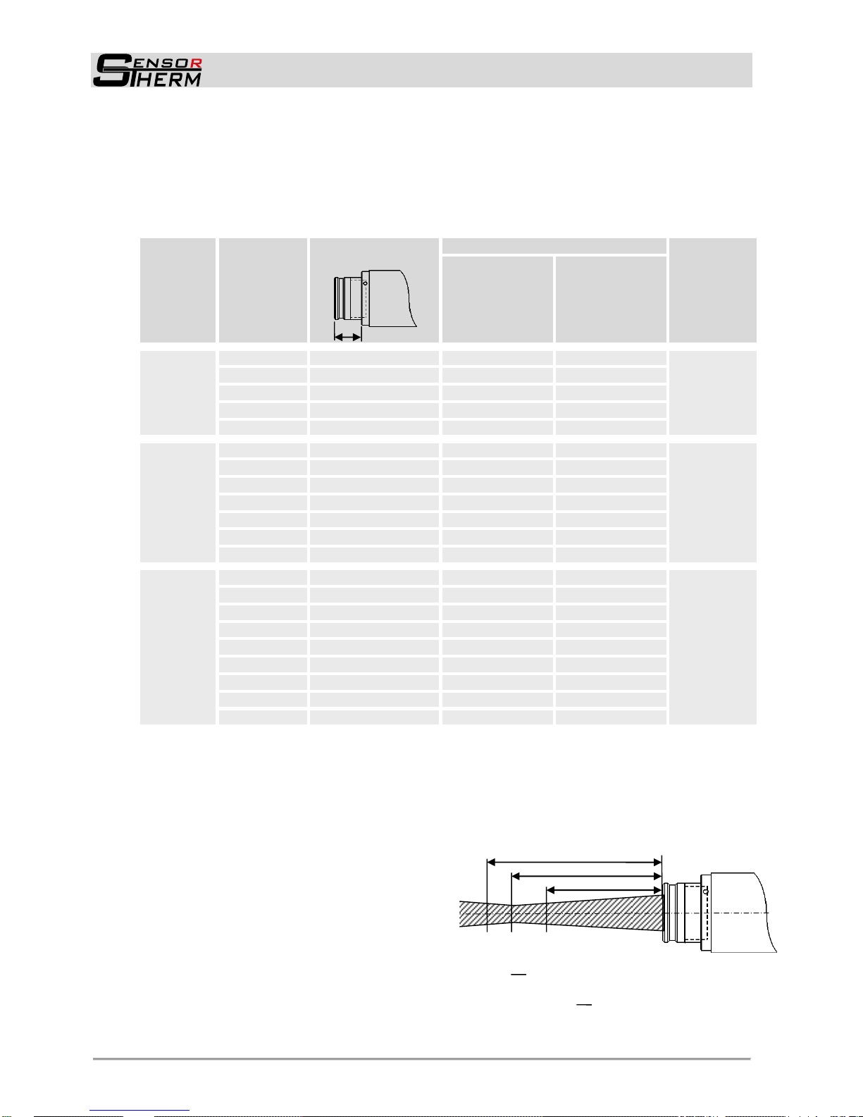
4.5 Spot Size Tables
The following tables show the optical data of the different device types. The values in the tables are exemplary, intermediate measurement distances must be determined by interpolation. If the measuring
distance differs from the adjusted or specified, a measurement is also possible, but the spot size
changes (usually it is larger, see 4.5.1 Calculation of the Spot Size Diameter outside the Focused
Distance). The measuring distances are specified from lens front.
Optics
Measuring
(focus)
distance
a [mm]
Optics pull-out
S [mm]
Spot size M [mm]
Aperture Ø
D [mm]
PI16
250–1000°C
PS09 and PI16
all other
temp. ranges
OP09-A0
170
16
1.7
1.3
14 mm
185
14.7
1.8
1.35
200
13.4
1.9
1.4
220
12.1
1.95
1.45
245
11
2
1.5
OP09-B0
260
16
2.1
1.6
14 mm
280
15
2.4
1.85
300
13.3
2.7
2.1
350
12.9
2.9
2.25
400
12.1
3.3
2.5
450
11.2
3.7
2.9
500
11
4.3
3.2
OP09-C0
480
16
4
3.3
14 mm
500
15.7
4.3
3.2
600
14.6
4.8
3.6
800
13.3
6.1
4.6
1000
12.5 8 6
1250
11.9
9.3
7
1500
11.5
11
8.3
1750
11.2
13
10
2000
11
14.5
11
4.5.1 Calculation of the Spot Size Diameter outside the Focused Distance
The spt size diameter determines the area on the measurement object from which 90% of the temperature radiation is detected by the pyrometer; therefore the spot size tables specify spot sizes for different
measuring distances (or focused distances).
For calculating intermediate values in front of and behind the focused measuring distance, the following
formula can be used or the Spot size calculator integrated in SensorTools (under 5.2):
a Focused distance
M Spot size diameter in the focused measuring
distance
a1 Measuring distance longer than focused meas-
uring distance
M1 Resulting spot size on measuring distance a1
a2 Measuring distance shorter than focused
measuring distance
M2 Resulting spot size on measuring distance a
2
D Aperture (specifies the spot size directly on the
optics’ lens, it differs depending on the optics
pull-out. The largest value applies at a fully extended optics, the lowest value is with inserted lens)
S
M
M2
M1
a2
a
a1
M1= (M+D)-D
a
1
a
M2= (M-D)+D
a
2
a

Infrared Temperature Switch (Hot Metal Detector) Polaris PS09 / PI16
Mechanical Installation
11
4.6 Parameters / Settings
4.6.1 Emissivity ε
The emissivity indicates the radiation
capacity of an object to be measured
relative to a calibration source with the
same temperature. To obtain correct
readings, the emissivity must be taken
into account in the measurement and
adapted for the respective measuring
material on the infrared switch. Each
material has a max. emissivity of 1.00
(=100%) which can be set.
In principle applies: to measure metals
in a short-wavelength spectral range as
possible, as here the emissivity is higher than in the long-wave range.
The specified values are guide values,
which were determined in the laboratory
and confirmed in application-oriented
measurements. They can vary due to
material-dependent conditions, as in
metals additionally to the surface texture alloy components play an important
role for the emissivity.
Is a range given, this is related to dif-
ferences in the nature of the surface
from smooth to rough, rough surfaces
have higher emissivities (for determining the correct emissivity also a
comparison measurement can be
performed with a thermocouple).
“n.s.“ means that no values exist for
this wavelength range (not specified),
e.g. because a reasonable measurement in this wavelength or temperature range is not possible.
The emissivities with "shiny" refer to
applications that are performed under
an inert gas or in a vacuum.
Measuring object
Emissivity [%]
PS09
PI16
Calibration source
1
1
Aluminum, shiny
n.s.
0.05-0.2
Aluminum, oxidized
n.s.
0.3-0.4
Aluminum, sandblasted, rough
n.s.
0.4-0.5
Aluminum, black anodized
n.s.
0.9
Lead oxidized
n.s.
n.s.
Bronze
0.2-0.4
0.2-0.4
Iron, liquid
0.15-0.3
0.1-0.25
Iron, shiny
0.3-0.4
n.s.
Iron, oxidized
0.7-0.9
0.65-0.85
Graphite
0.8-0.92
0.8-0.9
Gold, shiny
0.02-0.05
0.02-0.05
Inconel, shiny
0.35-0.45
0.4
Inconel, oxidized
0.65-0.75
0.6-0.7
Copper, shiny
0.10
0.05-0.1
Copper, oxidized
0.3-0.7
0.2-0.8
Magnesium, shiny
n.s.
0.15-0.2
Magnesium, oxidized
n.s.
0.3-0.5
Brass, shiny
0.5-0.7
0.5-0.7
Brass, oxidized
0.6-0.8
0.6-0.7
Molybdenum, oxidized
0.7-0.9
0.7-0.85
Nickel
0.22
0.15-0.2
Porcelain, glazed
0.6
0.6
Porcelain, rough
0.8-0.9
0.8-0.9
Platinum
0.4
0.35
Soot
0.95
0.95
Chamotte
0.45-0.6
0.45-0.6
Slag
0.85
0.8-0.85
Silver, shiny
n.s.
n.s.
Silver, oxidized
0.1-0.2
0.05-0.2
Steel, shiny
0.4-0.55
0.3-0.45
Steel, oxidized
0.8-0.9
0.7-0.9
Steel, rolled
0.8-0.9
0.8-0.9
Stoneware, glazed
0.86-0.9
0.8-0.9
Stainless steel
0.4-0.9
0.4-0.9
Titanium, shiny
0.35-0.45
0.3-0.4
Titanium, oxidized
0.55-0.85
0.55-0.85
Tungsten, shiny
0.3-0.4
0.3-0.4
Tungsten, oxidized
0.7-0.9
0.7-0.85
Brick
0.85-0.9
0.8-0.9
Zinc
0.45-0.58
0.45-0.55
Measurement deviations at a 10% false set emissivity
at a temperature of 700°C:
+10%
6.5°C
10.5°C
-10%
7°C
11.5°C

Infrared Temperature Switch (Hot Metal Detector) Polaris PS09 / PI16
Mechanical Installation
12
4.6.2 Response Time t90
The response time specifies the time that an infrared measuring device requires to track 90% of a
sudden temperature change on the signal output.
The response time depends on the requirements of the respective measuring task and can be adjusted.
If a short response time is selected, the temperature measurement follows the actual temperature
curve accurately. Short setting thus allowing the detection of briefly occurring temperature peaks,
which occur especially in fast heating processes or fast moving samples.
At longer response times, the measurement signal is smoothed and average values for temperature
fluctuations are formed caused by the inertial measurement.
4.6.3 Simulate a Switching Temperature
The switching outputs can be checked by simulating a switching temperature.
4.6.4 Baud Rate
The baud rate can be set between 1.2 and 57.6 kBd.
4.6.5 Address
In bus operation with RS485, an address between 00 and 97 can be assigned.
4.6.6 Interface Delay (Answer Delay)
During operation of the infrared switch via RS485, it may happen that the connection is not fast enough
to detect the response of the infrared switch to a command from the master, e.g. because the line is still
busy with sending before receiving. This sometimes occurs in older PCs or interface adapters or by
slow switching times of interface adapters and manifests itself in transmission errors of interface commands, so errors when parameters are changed or of measured values transmission.
In this case a delay for delaying the data transfer can be entered, the value specifies the main circulating time and can be set from 00-20. The transmission of commands to the connected device is thus
somewhat delayed, but it can work with existing peripherals.

Infrared Temperature Switch (Hot Metal Detector) Polaris PS09 / PI16
Configuring via SensorTools Software
13
5 Configuring via SensorTools Software
5.1 Program Start
Starting the software opens
the main window of the program. The Polaris is not connected automatically.
Since the Polaris is not a
measuring instrument, the
temperature reading functions in the main window of SensorTools are not functional.
5.1.1 Connecting the Polaris
For successful communication with the Polaris it has to be connected first.
Select the computer’s com port the device is connected to. Also a COM port must be
selected when connecting via an USB converter.
Press the search button if the com port is unknown. The device will be connected
automatically if the port is found.
Press the connect button to connect the device to the software. All device settings will
be read out and displayed in the software.
The button changes to “Disconnect” when connected. Click to disconnect.
The status line informs about device and connection status.
5.2 Setting Window
The setting window will appear as soon as the connection
is established.
The response time t90 (see 4.6.2) can be adapted to the
measurement conditions.
Selecting "Minimal" the Polaris works with the shortest
possible devices response time of 4 ms.
Under "User definded", times up to 10 s can be entered.
The Emissivity (see 4.6.1) is used for adaptations to the
material surface properties.
Limit switches:
- Limit value: Activates the corresponding output (Port)
at the entered limit value.
- Hysteresis: The hysteresis is the value at how many
degree below the limit value the output is switched
back.
- Logic: The state of the digital outputs can be set:
- NO (normally open): outputs have in active state 24
volts (precicely the power supply voltage, output
max. 30 mA) to the pins and in inactive state 0 V.
- NC (normally closed): outputs have in active state 0 volts to the pins and in inactive state 24 V
(precicely the power supply voltage, output max. 30 mA)
Laser targeting light: turns on and off the laser targeting light.
CAUTION, Laser Radiation, Laser Class 2:
Never look into the direct or reflected laser beam.
Do not point the laser to anyone.
If laser radiation hits the eye, the eyes must be intentionally closed and the head im-
mediately moved out of the beam.
Select PC
interface
or search
automatically
Connect with
software
Status line
Homepage link

Infrared Temperature Switch (Hot Metal Detector) Polaris PS09 / PI16
Configuring via SensorTools Software
14
Port test:
Enables testing of the outputs by simulating a switching temperature.
The simulation automatically stops after 3 seconds.
Interface:
For setting the baud rate (see 4.6.4), device address (see 4.6.5)
and interface delay (see 4.6.6).
Service functions
To back up, for printing or restore device parameters or create service files for
remote diagnosis of problems.
- Create configuration file: A configuration file includes all device settings made by user. This can
be used e.g. to setup a new device with the same values
and settings or to save the current status in case of a device replacement.
- Load Configuration file: load a previously saved configu-
ration data in the device.
- Print parameters: Prints the parameters of the currently
connected device.
- Print configuration file: Prints a saved file.
- Create service file: A service file includes all device data
and all software settings made by user. Creating such a file
can be useful if a problem can’t be solved and help from
our service could be useful.
- Upload service file: Transmitting a (possibly modified) file
to the device it was created from.
Spot size calculator
The spot size calculator (from the
main window) is used to calculate
the spot size diameter in front and
behind the focused measuring distance (see 4.5.1). To do this, fill the
white fields with the basic data (see
4.5 spot size tables), then values
in the gray fields can be calculated.
Start simulation
Specify simulation
temperature
Check output state

Infrared Temperature Switch (Hot Metal Detector) Polaris PS09 / PI16
Technical Data
15
6 Technical Data
Model
PS09 PI16
Temperature ranges
550–1400°C
650–1800°C
250–1000°C
300–1300°C
350–1800°C
Spectral range
0.7–1.1 µm
1.45–1.8 µm
Switch temperatures
Can be set within the limits of the temperature range
Signal processing
Digital
Measurement uncertainty
± 1% of adjusted switching point temperature (TA=23°C, ε=1, t90=1 s)
Repeatability
0.5% of adjusted switching point temperature (TA=23°C, ε=1, t90=1 s)
Response time t90
4 ms, adjustable to 10 s
Emissivity ε
20–100%
Power supply
24 V DC (possible range 12 – 30 V DC)
Power consumption
Max. 0.5 VA (without switching output current)
Switching outputs
2 transistor outputs, switches the positive supply voltage to the output
(positive switching), max. current 30 mA
Digital interface
RS232 or RS485, addressable, baud rate 1.2–57.6 kBd,
galvanically isolated
Parameters
changeable and readable via serial interface:
switching temperature, emissivity, response time, device temperature,
address, baud rate
Sighting
Laser targeting light (laser class 2, max. output power 1 mW, 635 nm)
Operation indicator
Green LED
Switching indicator
2 yellow LEDs
Weight
300 g
Protection class
IP65 (according to DIN 40 050) with mounted connection cables
Ambient temperature
0–70°C
Storage temperature
-20–70°C
Rel. humidity
No condensing conditions
CE label
According to EU directives for electromagnetic immunity
6.1 Storage
Store packages under the following conditions:
Do not store outdoors
Store dry and dust-free
Do not exposed to corrosive media
Protect from direct sunlight
Avoid mechanical vibrations
Storage temperature: -20 to 85°C
Relative humidity: max. 95%,
no condensing conditions
6.2 Dimensions
Dimensions in mm

Infrared Temperature Switch (Hot Metal Detector) Polaris PS09 / PI16
Technical Data
16
6.3 Composition of the Type Number
The equipment version of the Polaris is encoded in the 18-digit model number as follows
(Example type number PS09 with 550–1400°C; laser targeting light, 2 switch outputs):
Digit
01
02
03
04
05
06
07
08
09
10
11
12
13
14
15
16
17
18
Expl.:
P S 0 9 0 5 5 0 1 4 0 0 1 1 2 4 3
2 Digit
Indication of the various points
Code
Meaning / Example
01-02
Series Polaris
PS
Polaris with Silicon detector
PI
Polaris with Indium-Gallium-Arsenid detector
03-04
Spectral range
09
0.7–1.1 µm (Si)
16
1.45–1.8 µm (InGaS)
05-08
Beginning of temperature range [°C]
0550
550°C
09-12
End of temperature range [°C]
1400
1400°C
13
Sighting
1
Laser targeting light
14
Serial interface
1
RS232
2
RS485
15
Lens type
2
Focusable optics
16-17
Minimum response time
43
4 ms
18
Outputs
2
2 transistor outputs
Measuring distance / Optics
A
Optics A (170-245 mm)
B
Optics B (260 - 500 mm)
C
Optics C (480 - 2000 mm)
6.4 Accessories
Ref. number
Meaning
AK32-02
Connection cable 2 m
AK32-05
Connection cable 5 m
AK31-02
Interface cable 2 m, including SensorTools software
AK31-05
Interface cable 5 m, including SensorTools software
DK4000
Interface converter RS485USB, 1.7 m cable, 9-pin Sub-D-connector
DK3000
Interface converter RS232USB, 1.7 m cable, 9-pin Sub-D-connector
NG12-00
Din-rail power supply 24 V DC, 1.6 A
NG15-00
Desktop power supply 24 V DC, 2.5 A
HA11-00
Stainless steel mounting bracket
BL11-00
Air purge accessory
KG60-00
Water cooling jacket for temperatures up to 140°C
HA10-10
Mounting bracket to be used with cooling housing KG60
HA21-00
Ball and socket swivel mount for water cooling jacket KG60

Infrared Temperature Switch (Hot Metal Detector) Polaris PS09 / PI16
Maintenance
17
7 Maintenance
CAUTION, switch off supply voltage.
Before beginning any maintenance, switch off power supply or pull connector on the Polaris to prevent injury by accidentally activated laser targeting light!
7.1 Cleaning
Clean the lens with a soft cloth and a little alcohol or acetone. Use only high-purity acetone to avoid residues.
The objective lens is not
to clean with solvents that contain acid
immerse in water or other liquids to clean
7.2 Calibration
To obtain the measurement accuracy, we recommend to re-calibrate the Polaris at Sensortherm periodically (annually) with the help of calibration sources.
8 Communication via Serial Interface / Interface Commands
Interface commands are used to communicate directly with a Sensortherm device. Commands can be
used to write an own access control or can be entered in the terminal field of the software SensorTools
(in the main window in the tab “miscellaneous”) or entered via a terminal software. Data is exchanged in
ASCII format with the following transmission parameters: 8 bit, 1 stop bit, even parity (8,1,e).
Command structure:
For successful communication the following sequence of a command is used:
Device Address - Command - Parameter
Device address: all interface commands are starting with the 2-digit device address (exception: in
the terminal field of the SensorTools software no address is required). In factory setting the device
address is 00 but can be change per command.
Device addresses from 00 to 99 are valid but 98 and 99 are with special functions. The global address 99 can be used to communicate with every device, independent of the set address. This allows
communication with devices which have unknown addresses. The address 98 is a group address
used for RS485 devices. Devices do not answer with this address, useful to change parameters of all
connected devices at the same time.
Command: command have to be completed with a carriage return <CR> (decimal 13).
Parameter (Unless otherwise specified, coded hexadecimal):
without parameter the command reads out the current set value. The answer at request commands
is the set value of the device corresponding to the possible settings described in the table. Answers
are normally finished with a <CR>. Deviating read commands are in parentheses in the respective
write commands.
With parameter the parameter will be set into the device. A setting command answers with
ok+<CR>, this means the command is accepted.

Infrared Temperature Switch (Hot Metal Detector) Polaris PS09 / PI16
Communication via Serial Interface / Interface Commands
18
Command
Parameter
Description / Settings
bn Read reference number (18-digit ASCII sequence)
Meaning: see 6.3 Type number
br X Baud rate (1-digit dec.)
X = 0-4, 6
0 = 1200 Baud 2 = 4800 Baud 4 = 19200 Baud
1 = 2400 Baud 3 = 9600 Baud 6 = 57600 Baud
em
XXXX
Emissivity (4-digit. dec.)
XXXX = 0020–1000 in ‰ (= Emissivity 2–100%)
ez X Einstellzeit t90 (1-stell. Dez.)
X = 0-6
0 = inherent time constant of the device
1 = 0.01 s 3 = 0.25 s 5 = 3 s
2 = 0.05 s 4 = 1 s 6 = 10 s
ga
XX Device address (2-digit decimal number)
00–97 = individual device address
99 = global address with answer
98 = global address without answer
gt Read device temperature (2-digit decimal number in °C)
XX=00–98°C
mb Read temperature range (8-digit hexadecimal number)
First four digits: beginning of temperature range in °C
Last four digits: end of temperature range in °C
sw1
XXXXYYYY
Switch temperature 1 (8-digit hex.)
XXXX=lower switch temperature in °C
YYYY=upper switch temperature in °C
sw2
XXXXYYYY
Switch temperature 2 (8-digit hex.)
XXXX=lower switch temperature in °C
YYYY=upper switch temperature in °C
sn Read serial number (5-digit decimal number)
tm Read Maximum device temperature (2-digit decimal number),
XX=00–98°C
ve Read device type and software version (6-digit decimal number)
1. and 2. digit: Device type Polaris PS/PI
3. and 4. digit: Month of software version
5. and 6. digit: Year of software version

Infrared Temperature Switch (Hot Metal Detector) Polaris PS09 / PI16
Index
19
Index
A
Accessories ......................................................... 16
Address ................................................................ 12
Alignment onto the measuring object .................... 8
Alignment with the laser targeting light .................. 9
Ambient temperature ............................................. 8
Answer Delay ....................................................... 12
B
Baud rate ............................................................. 12
C
Cable colors and pin assignment .......................... 6
Calibration ............................................................ 17
Cleaning ............................................................... 17
Communication via serial interface ...................... 17
Configuring via SensorTools software ................. 13
Connecting the Polaris......................................... 13
E
Electrical connection .............................................. 6
Emissivity ε .......................................................... 11
F
Factory settings ..................................................... 6
I
Intended use .......................................................... 4
Interface commands ............................................ 17
Interface converter (accessory) ............................. 8
Interface delay ..................................................... 12
Interface settings ................................................. 14
L
Laser targeting light .......................................... 9, 13
M
Maintenance ......................................................... 17
Mechanical installation ........................................... 8
Mounting ................................................................. 8
P
Parameters / settings ........................................... 11
Power supply .......................................................... 6
R
Response time t90 ................................................. 12
S
Scope of Delivery ................................................... 4
Serial Interface RS232 or RS485 ........................... 7
Service functions .................................................. 14
Setting the measuring / focus distance .................. 9
Setting window ..................................................... 13
Simulate a switching temperature ........................ 12
Software SensorTools .......................................... 13
Spot size calculation ............................................. 10
Spot size calculator .............................................. 14
Spot size tables .................................................... 10
Status LEDs ........................................................... 6
Switching outputs ................................................... 7
T
Technical data ...................................................... 15
Type number ........................................................ 16

Sensortherm GmbH
Hauptstraße 123
65843 Sulzbach
Tel: +49 (0)6196 64065-80
Fax: +49 (0)6196 64065-89
E-Mail: info@sensortherm.com
Internet: www.sensortherm.com
© Sensortherm GmbH Polaris_PS09_PI16 (May 11, 2017)
 Loading...