

Sensortech Systems ST-3300 Installation Instructions Manual
ST-3300
Ceramic Face Sensor
with Attached Sensor Electronics Unit
Installation Instructions
Sensortech Systems, Inc.
2221 E. Celsius Avenue Unit B
Oxnard, California USA 93030
805-981-3735 main
805-981-3738 fax
www.sensortech.com
© Sensortech Systems, Inc. 2016 Page 1 of 13 Rev.8-2016
Figure
1.
he Sensor Electronics
Figure
2.
ST-3300 Low Temperature Moisture Measurement System
The main components in the system are:
1.
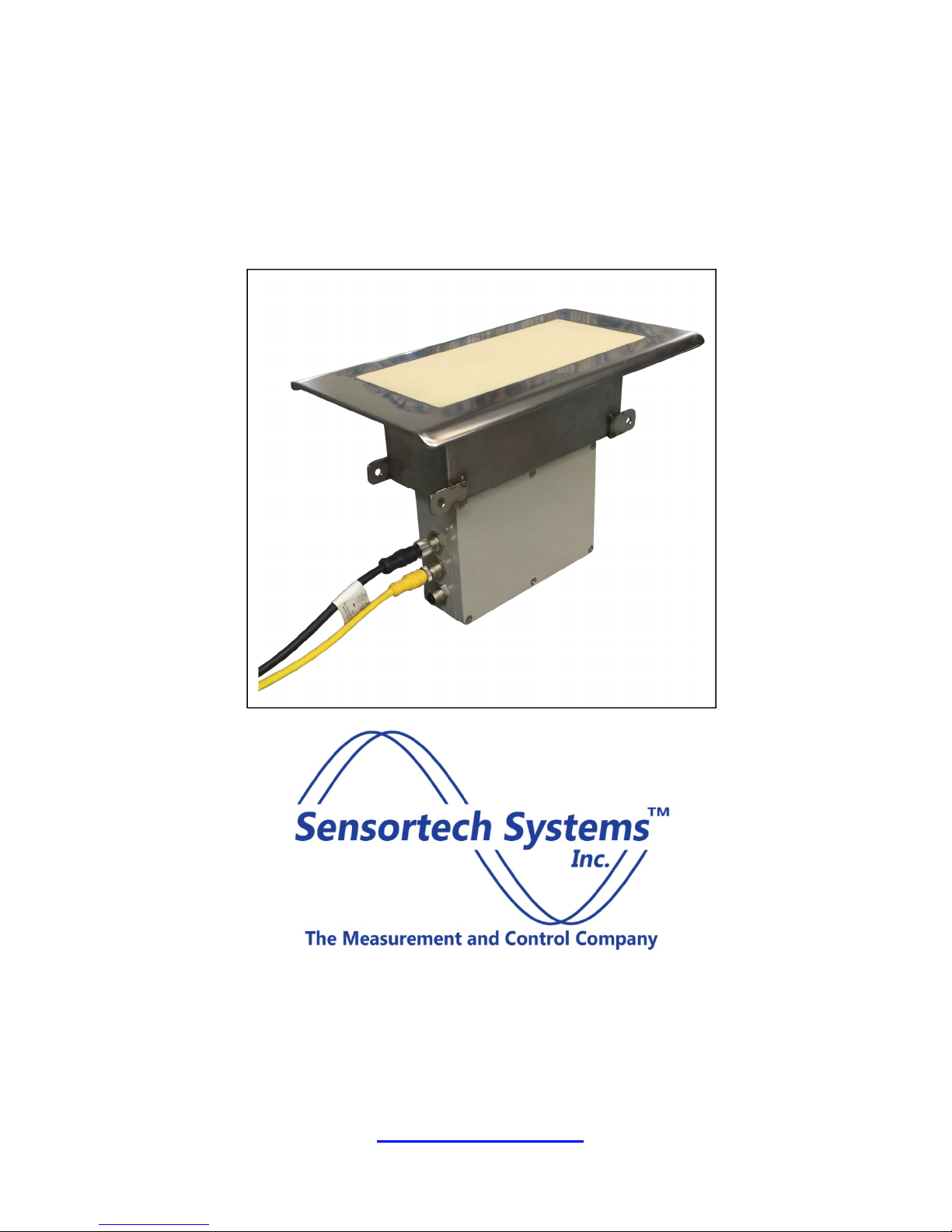
ST-3300 Ceramic Face Sensor with Attached
3.
Sensor Electronics Unit – a ceramic face sensor
designed to be in contact with the board product
mounted between rollers. T
Unit is mounted directly below the Sensor
Antenna. The Sensor is rated for +32 to +122°F
(0 to +50°C) operation. The Sensor Electronics
Unit is contained in a NEMA4 rated metal
enclosure containing the RF moisture
measurement and control electronics. Power
requirements are +15V/-15V dual 40W supply.
Communications are via RS485 and selfpowered, isolated 4-20mA output. The
Power/Interface Option shown below which
conveniently provides necessary power and I/O
connectivity.
Ceramic Face Sensor Antenna with
Attached Sensor Electronics Unit
Power/Interface Option
2.
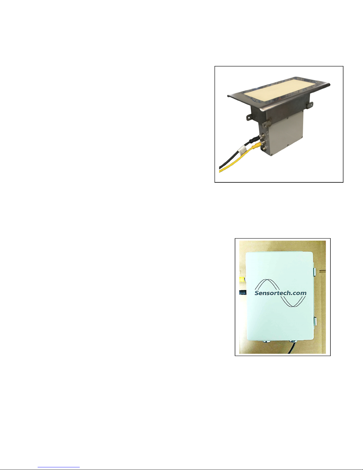
ST-3300 I/O Unit – a NEMA4 rated metal enclosure
containing +/-15V DC power supply and control
signals for the Ceramic Face Sensor with Attached
Sensor Electronics Unit. The I/O Unit connects to
the user’s A/C power and provides terminal blocks
for user interface to RS-485, 4-20mA output and
Digital Input signals.
I/O Unit
© Sensortech Systems, Inc. 2016 Page 2 of 13 Rev.8-2016
© Sensortech Systems, Inc. 2016 Page 3 of 13 Rev.8-2016
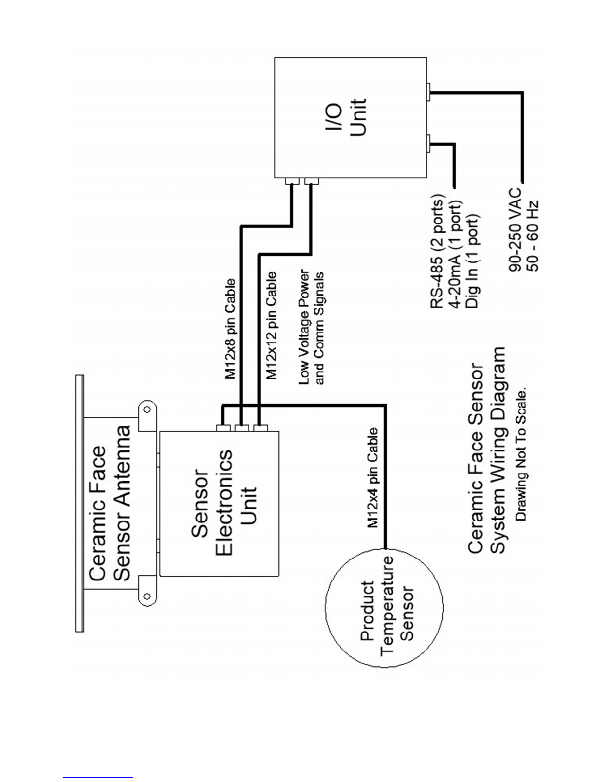
Figure
3.
System Wiring Diagram
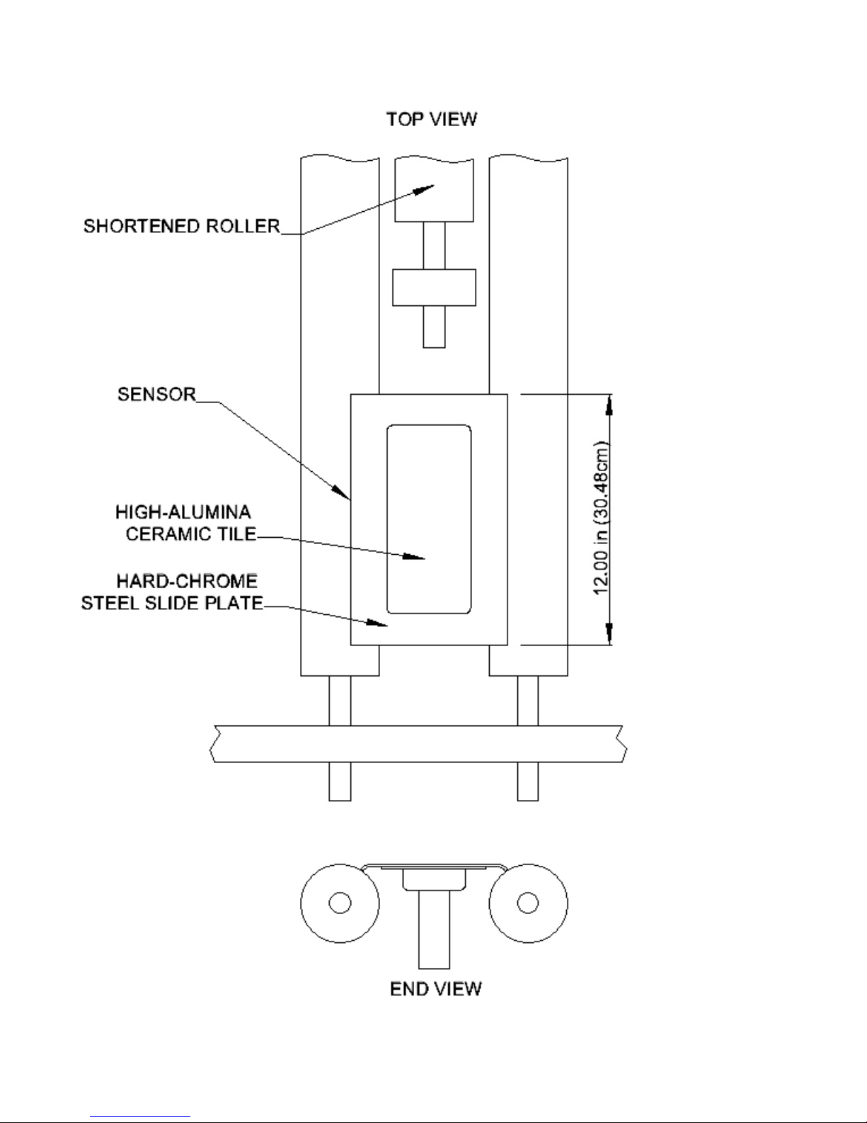
Figure
4.
© Sensortech Systems, Inc. 2016 Page 4 of 13 Rev.8-2016
Sensor Installation Diagram
 Loading...