

ST-2200 Sensor
with Attached Electronics
Installation Instructions
© Sensortech Systems, Inc. 2016 Page 1 of 16 Rev.7-2016
Sensortech Systems, Inc.
2221 E. Celsius Avenue Unit B
Oxnard, California USA 93030
805-981-3735 main
805-981-3738 fax
www.sensortech.com
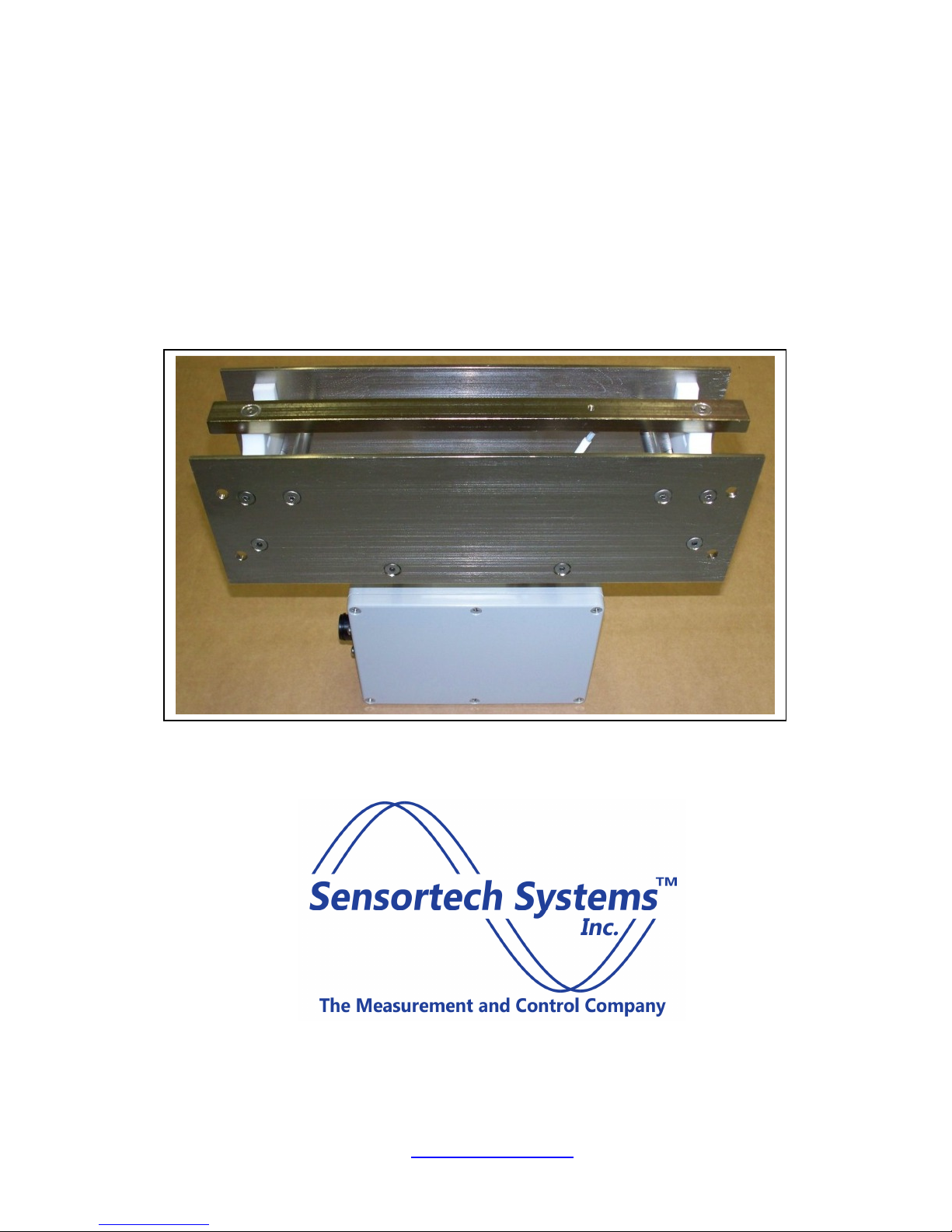
ST-2200 Sensor System:
Figure
2. ST-2200
Sensor
The two main components in the system are:
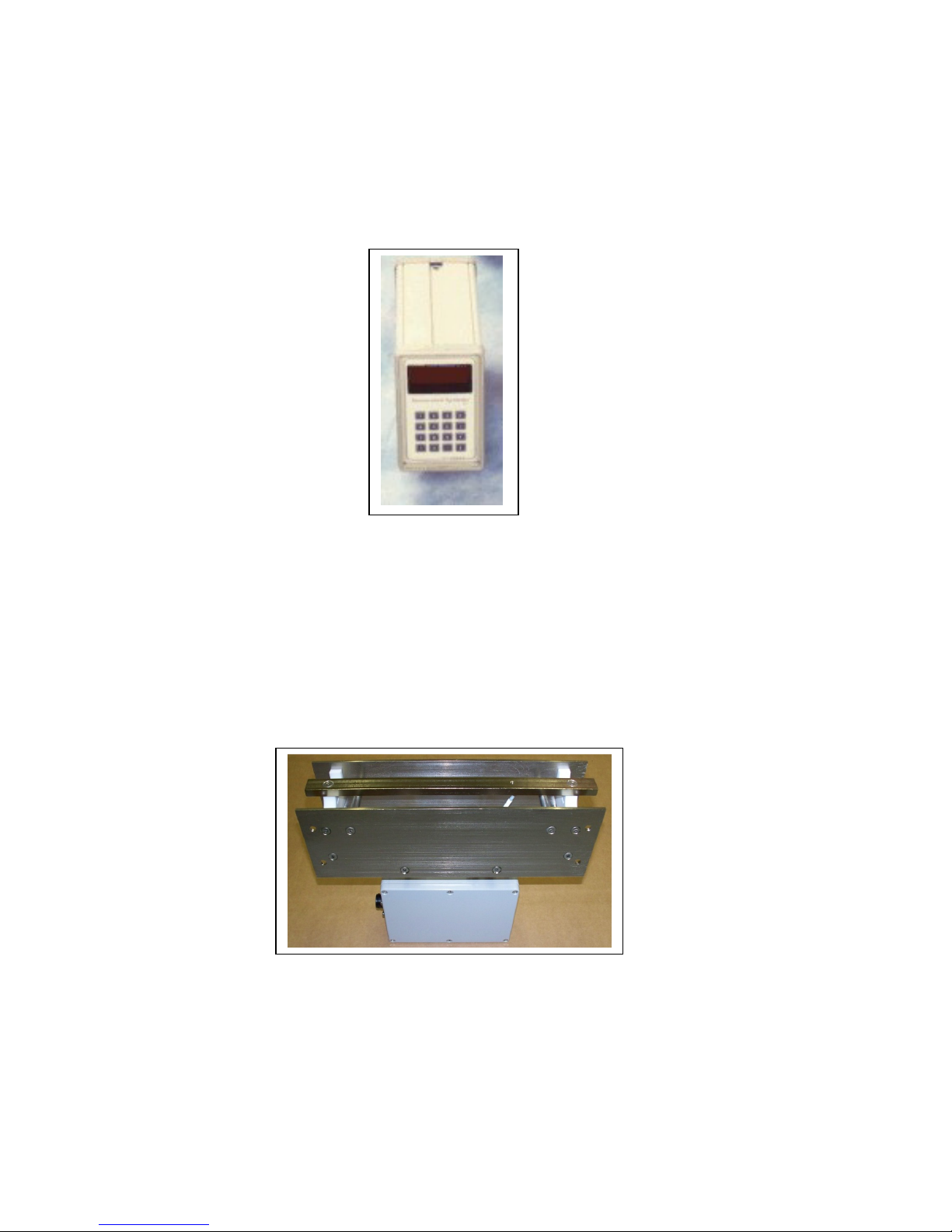
1. ST-2200 Processor Unit (Processor) – an intelligent measurement and control unit that
connects to the Sensor Electronics Unit and provides moisture measurements via serial, 420mA and front panel LED display. The Processor is also referred to as the Signal Processor.
Figure 1. ST-2200 Processor Unit
2. ST-2200 Sensor with Attached Sensor Electronics (Sensor) – a NEMA12 rated metal
enclosure containing the moisture measurement and RF switching electronics is attached to
the bottom side of the open-frame planar sensor. The Sensor is mounted in-line on the
outside of the dryer. The Sensor with Attached Sensor Electronics is also referred to as the
Antenna.
© Sensortech Systems, Inc. 2016 Page 2 of 16 Rev.7-2016
with Attached Electronics Unit

ST-2200 Sensor System Installation Guidelines
Locating the Sensor:
Select a location to install the ST-2200 Sensor where the board will remain flat over the Sensor
for the full length or width of board travel over the Sensor.
Avoid locations where the air gap between the board and Sensor may change during board travel
due to changing slope or roller height on Dry End Transfer conveyor or Takeoff Cascade.
Preventing board bounce while arriving, travelling over and leaving the Sensor results in the best
measurement accuracy. In addition, it is desirable to prevent a board impacting the Sensor due to
board bounce or changing angle of approach or departure from the Sensor.
The spacing between the top of the Sensor to the bottom of a board is critical for good
measurement accuracy. The specification for the air gap between the board and Sensor is 0.25
inches (6.35mm). A typical ST-2200 Sensor is installed on a Mounting Beam centered between
level rollers 12-18 inches (30-45cm) apart.
When measuring board traveling over the Sensor for the full length of the board, the
recommended minimum distance from the end of the Take-off Cascade is calculated as follows:
Sensor Location = Longest Board Length + 1 Roller (from the Take-off Cascade)
i.e. if the Longest Board Length = 14 feet (4.3m) and the roller spacing is 12-18 inches (30-
45cm) then the mounting beam for the Sensor should be installed greater than 15 feet
(4.6m) from the end of the Take-off Cascade.
When measuring board traveling over the Sensor for the full width of the board, the
recommended minimum distance from the Inverter on the Dry End Transfer is calculated as
follows:
Sensor Location = Widest Board Width + 1 Roller (from the Inverter)
i.e. if the Widest Board Width = 4 feet (1.22m) and the roller spacing is 12-18 inches (30-
45cm) then the mounting beam for the Sensor should be installed greater than 5 feet
(1.5m) before the Inverter.
© Sensortech Systems, Inc. 2016 Page 3 of 16 Rev.7-2016

Preparing for the installation:
1. Fabricate and install a height adjustable beam for installing the Sensor after the kiln or dryer
between the rollers. Ensure the adjustment range allows the Sensor to be positioned at 0.25
inch (6.35mm) spacing from bottom of board when resting on rollers.
2. Run a 10-16 AWG Earth Ground wire from local ground source to Sensor mounting location.
3. Mount the Processor Unit in the desired location per supplied drawings (see Figure 7 & 8). It
is recommended to mount the Processor Unit near the Sensor mounting location and run the
4-20mA cable for moisture output to the control room Process Controller / PLC.
4. Install conduit or cable run for Processor Cable from the Sensor to the Processor Unit.
5. Provide AC plug receptacle for main AC power to Processor Unit (110-240VAC 20A Service).
6. Run an Earth Ground wire from local ground source to Processor Unit mounting location.
7. Install any external equipment / PLC cabling to Processor Unit terminal block signals (RS-232
serial link, 4-20mA loop, external alarms, product detectors, etc.).
Important:
Do not mount the Sensor with attached Sensor Electronics Unit where excessive heat
transfer will occur. Ensure that Sensor is located away from exhaust gases venting from
the dyer to prevent measurement drift or electronics failure due to the attached Sensor
Electronics Unit over-heating.
Provide an Earth Ground for the Sensor. Ensure a side plate of the Sensor is connected to
local Earth Ground. Add a 10-16 AWG direct wire connection from the Sensor with
attached Sensor Electronics to a local Earth Ground potential. Ensure sensor frame is
grounded to process frame or conveyor frame, etc. This is not a safety requirement, but
may influence instrument performance.
© Sensortech Systems, Inc. 2016 Page 4 of 16 Rev.7-2016
© Sensortech Systems, Inc. 2016 Page 5 of 16 Rev.7-2016
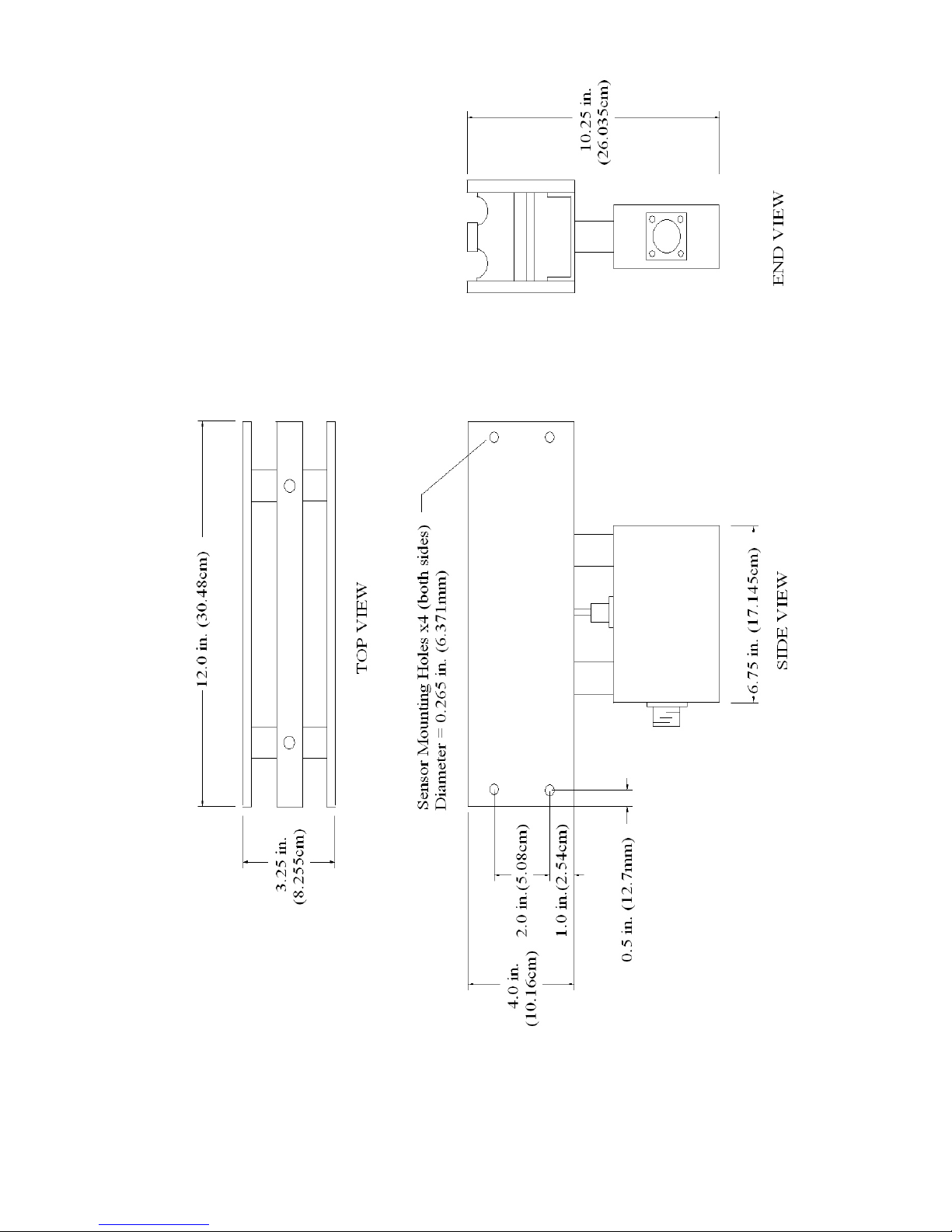
Figure 3. 12
-
inch (30.48cm) Sensor Dimensions

© Sensortech Systems, Inc. 2016 Page 6 of 16 Rev.7-2016
Figure
4
. 36-inch
(91.44cm)
Sensor Dimensions

Mounting the Sensor:
The Sensor is typically mounted after the dryer between rollers or under a conveyor surface. The
Sensor with attached Sensor Electronics Unit is rated from 0°C to 50°C ambient temperature and
should be on a low vibration steel channel or angle beam mounted to the floor. A less desirable
mounting approach due to increased vibration is to install the sensor on a steel channel or angle
beam mounted to the existing roller support frame. The Sensor is attached to the beam using the
four mounting holes on the ends of the Sensor frame (see Figure 5 & 6). The open-frame Sensor
construction allows debris to fall through the Sensor and the bottom of the Sensor should not be
blocked by the beam to allow debris to exit.
A critical dimension for a roller conveyor process is the 0.25 inch (6.35mm) product to Sensor air
gap between the top of the Sensor to the bottom of a board across the board width. The air gap
distance can be checked with anything that is 0.25 in. (6.35mm) in diameter (a drill bit, 1/4inch bar
stock, etc.) and a straight edge that rides on top of the conveyance system (rollers, belt, etc.). The
concept most important here is that the Sensor is coplanar and parallel to the product. If one end
of the Sensor is further from the product, it will be less sensitive to changes in moisture than the
opposite end that is closer. This can be further aggravated if the product does not have uniform
moisture distribution. See Parallel Antenna Verification below. The antenna and sensor should
also be isolated as much as possible from vibration. Vibration can loosen nuts, bolts, and
electronic components.
The Processor Cable, a multi-conductor shielded twisted pair cable is used to connect the Sensor
Electronics Unit to the Processor Unit. The standard Processor Cable is 25 ft. x 0.5 in. (7.62m x
12.7mm) in length. The Processor Cable is rated from -40°C to +85°C ambient temperature.
Custom processor cable lengths up to 1000 ft. (300m) are available and higher temperature rated
cable is available by special order.
Parallel Antenna Verification (on roller conveyors):
This procedure should be done with factory default settings. Place a Standardization Plate (or
board product with approximate dimensions of 24 in. x 24 in. (61cm x 61cm) covering one half of
the Sensor. Note moisture display value. Move the Standardization Plate over one half of the
other end of the Sensor. Make sure to use the same section of plate with same orientation. Note
moisture display value. If there is a difference in moisture display values, the antenna is not
parallel to the product. The side that displayed higher readings is closer to the product than the
other end of the Sensor. The mounting beam or Sensor mounting bolts will need to be adjusted
up or down until both ends of the Sensor are at 0.25 in. (6.35mm) air gap spacing and moisture
values are similar within +/- 1 are displayed when the Standardization Plate is placed covering
one half at each end of the Sensor.
© Sensortech Systems, Inc. 2016 Page 7 of 16 Rev.7-2016

Leveling the Rollers:
Lay a level or straight edge across the six rollers near their ends.
Sensor
IMPS Sensors
The maximum runout for each of the three rollers preceding
and following the sensors is 0.02 inches (0.5 mm).
The top surface of the IMPS Sensors should be 0.25 +/- 0.02 inches (6 +/- 0.5mm) from the bottom of the board.
Mount the sensor 0.125 inches (3mm) down from the surface of the bracket. This protects the sensor from the
leading board edge.
Shim the two outer rollers’ bearing assemblies so that they are level.
Shim the remaining four rollers’ bearing assemblies so that each roller is within 0.01 inches
(.25mm) of level.
Lay the level along the first roller. Shim its bearing assembly on the other side so that it is level
lengthwise.
Lay a level across the six rollers near their ends.
Shim the last roller’s bearing assembly so that it is level with the first roller.
Shim the remaining four rollers’ bearing assemblies so that each roller is within 0.01 inches
(.25mm) of level.
Use a feeler gauge to measure the space from the top of Sensor to bottom of a board or use the
ST-2200 Standardization Plate for board alignment. To make a feeler gauge for air gap
alignment, cut two 12 in. (30 cm) lengths of 0.25 in. (6.35 mm) square or round rod and place on
Sensor below the Standardization Plate and adjust the beam until the rods just touch the bottom
of the Standardization Plate. Ensure both ends of the Standardization Plate are coplanar to the
tops of the Sensor. Adjust the Sensor mounting Beam and adjacent 4-6 rollers until the Sensor is
coplanar to the rollers and the rollers are level to each other.
© Sensortech Systems, Inc. 2016 Page 8 of 16 Rev.7-2016

Level
Rollers
Roller
Conveyor
Frame
Level
Bearing
Shim
© Sensortech Systems, Inc. 2016 Page 9 of 16 Rev.7-2016

Figure 5. Detail of Sensor Installed on a Mounting Beam
© Sensortech Systems, Inc. 2016 Page 10 of 16 Rev.7-2016

Figure 6. Example of 36-inch (91.44cm) Sensor Installed on a Mounting Beam
© Sensortech Systems, Inc. 2016 Page 11 of 16 Rev.7-2016

Mounting the Processor Unit:
Figure
7
. Processor Unit Dimensions
The ST-2200 Processor Unit (Processor) is typically panel mounted in an enclosure next to the
line for ease of access during maintenance calibration or in a control room within the Processor
Cable length to the Sensor.
To panel mount the Processor, remove the front plastic bezel and attach the Processor
mounting brackets, provided with the Processor Unit, to the Processor housing. It is
necessary to loosen the Processor front panel in order to install the mounting brackets
onto the housing.
When locating the Processor, allow sufficient depth for the length of the unit plus at least 3inches (76mm) to accommodate cables at rear of unit.
© Sensortech Systems, Inc. 2016 Page 12 of 16 Rev.7-2016

Figure
8
. Processor Panel Cut
-
out Dimensions
To panel mount the Processor, use the panel cut-out mounting diagram below to cut out a
rectangular hole for the front panel. Drill four thru holes to install bolts to attach to the Processor
mounting brackets.
© Sensortech Systems, Inc. 2016 Page 13 of 16 Rev.7-2016

ST-2200 System Power-up:
Figure
9
. Processor Unit Rear Panel Connections
Please verify the following before applying power to the ST-2200 Processor:
1. Securely tighten the black Amphenol connector located on the side of the Sensor.
2. Ensure the nine wires on the Processor Cable from the Sensor Electronics Unit are
wired into the terminal block labeled SENSOR INPUT on the rear of the Processor. The
wires are labeled 1 thru 9, and should be installed in sequential order, starting with wire
labeled #1 on the left side terminal block connector labeled +12V. Continue installing
each wire in number sequence ending with wire labeled #9 on the right terminal block
connector labeled AIO- (see Figure 9).
3. Ensure the Processor and Sensor are moisture free and the ambient temperature
environment is between 0°C to +50°C.
Note: Do not over tighten the terminal block screws.
For additional technical support, email us at
support@sensortech.com
or call 805-981-3735 M-F between 8AM-4:30PM Pacific Standard Time
© Sensortech Systems, Inc. 2016 Page 14 of 16 Rev.7-2016

ST-2200 PROCESSOR COMMANDS - QUICK REFERENCE
Function
Number
00
01 Product code 1 10 1
02 Password ****** ****** ******
03 Sample Rate 1 1S 10ms
04 Damping 0 120 0
05 Decimal selection 0 2 1
06 Pre-zero
07 Standardization 25
08 Sampling Mode 0 4 1
09 Batch Average mode No Yes No
10 Void Time 1
11 ATRO No
19 New Password ******
20 Limits
21 Low moisture limit -5.0 99.9 -5.0
22 High moisture limit 0 9999 100
23 4 mA out moisture 0 100 0
24 20 mA out moisture 0 100 100
25 Auto product loss 0 9999 0
26 Auto product return 0 9999 9999
27 Timed sampling fill time 0 99 1
28 Timed sampling purge time 0 10 1
29 Reference 0 100 15
30 Dielectric
31 Dielectric mode 1 3 1
32 Dielectric span -99.999 99.999 1
33 Dielectric zero -999.99 999.99 0
40 Temperature
41 Temperature compensation No Yes No
42 Temperature coefficient...Kt1 -99.999 99.999 0
43 Temperature coefficient...Kt2 -99.999 99.999 0
44 Temperature nominal -999.99 999.99 0
50 Weight
51 Weight compensation No Yes No
52 Weight coefficient...Kw N/A N/A 0
53 Weight nominal -999.99 999.99 0
54 Weight...keyboard entry 0 999.9 0
60 Distance
61 Distance compensation Off On Off
62 Distance coefficient...Kd -99.999 99.999 0
63 Distance nominal N/A N/A 0
Function
Description
General
Range
Low
Range
Range
High
Range
Default
© Sensortech Systems, Inc. 2016 Page 15 of 16 Rev.7-2016

Number
100 Utilities
101 Default CAUTION!!
102 Code Copy
120 I/O Configuration
121 Temperature span -99.999 99.999 1
122 Temperature zero -999.99 999.99 0
123 Weight span -99.999 99.999 1
124 Weight zero -999.99 999.99 0
125 Distance span -99.999 99.999 1
126 Distance zero -999.99 999.99 0
127 4 mA calibration
128 20 mA calibration
129 Equal High referencing No Yes No
130 Alpha-numeric display intensity 00 77 33
131 Numeric Display minimum -999.99 999.99 -.2
132 Numeric Display maximum 0 9999 9999
133 Host Interface Baud Rate 300 19200 9600
134 Host Interface Device Address 0 99 0
135 Communication Type RS232 RS485 RS485
136 Host Options 0 255 56
137 Product Code No Yes Yes
138 Safe Alarm No Yes No
139 Compensation WTD 1 6 WTD (1)
140 Diagnostics
141 Voltmeter Display
142 Antenna frequency Display
143 Low frequency Display
144 High frequency Display
145 Raw Dielectric Display
146 Dielectric pre-zero value 0.0000
147 Dielectric standardization value 50.00
148 Dielectric loss input Display
155 Raw temperature Display
156 Raw weight Display
157 Raw distance Display
158 Delta frequency Display
160 Display test Display
161 Keyboard test Display
162 Software Version 210
Description
Low High
Default
© Sensortech Systems, Inc. 2016 Page 16 of 16 Rev.7-2016
 Loading...